How To: Build and Hardwire an Auxillary Input to OEM Stereo
 03-05-07, 05:28 PM
#1

Edit for 2014:
-Yes, you can use a bluetooth stereo adapter to get A2DP wireless audio with this modification, The Monoprice unit (id 7364 ~$20 http://www.monoprice.com/Product?c_i...seq=1&format=2) works just fine.
Concept:
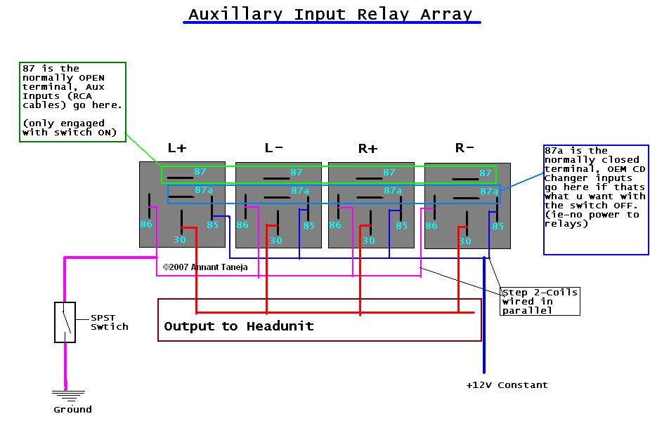
How this works is that 4 SPDT (single pole double throw) 12v Relays are used to switch between the factory CD changer signal and external source (must be preamp) before the sound goes into the OEM amplifier.
because of this, you MUST have a somewhat working CD changer, as long as it turns on you're fine.
This SHOULD work on any lexus model that uses a CD changer that gives out a preamp. output (pretty much all iirc).
Confirmed Applications:
LS400 (all years incl. NAK** and Navi cars)
GS300/400 (98-02 incl. Nak**, ML, and Navi)
GS300 (1st gen https://www.clublexus.com/forums/sho...6&postcount=16)
SC300/400 (all years)**
**=will intercept signal between CD Changer and Headunit, not amp, needs to be done on SC300/400 (all), 98-00 GS3/4 with NAK, and 98-00 LS400 with NAK (NOT needed on non-nak 98-00 LS/GS)
Should work on:
IS300 (all years)
LX450/470 (pre 02)
SC430 (all years)
if i missed any its not because they wont work, its because i havent checked
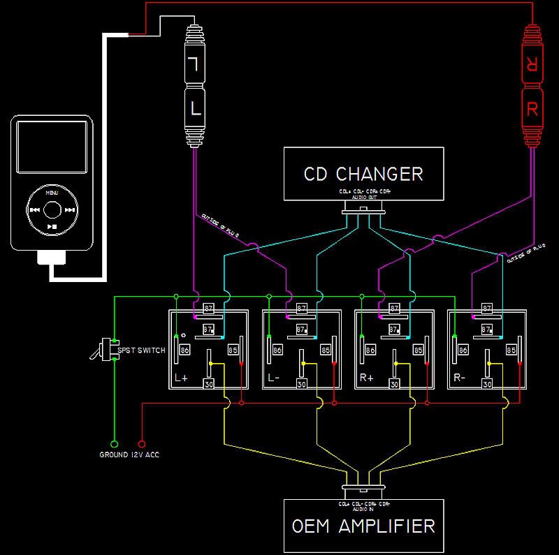
Here is a basic overview of how the whole thing will look like, including specific instructions on wiring the trigger switch
Materials:
Tools:
Props:
Salimshah for telling me to go check my wiring again
Horta for moral support
ADDENDUM:
new pic 1-2011 below

^flashy layouts courtesy of member rgarjr
also, let me make it clear. I AM NOT SELLING THIS.
i have materials enough for 1-2 more ppl and they have contacted me during the development phase of my little project.
If, however, there is enough demand AND the CL Admin/Moderators don't mind there is possibility to change that.
Donations are accepted to help cover the cost of development
pm me for paypal
-Yes, you can use a bluetooth stereo adapter to get A2DP wireless audio with this modification, The Monoprice unit (id 7364 ~$20 http://www.monoprice.com/Product?c_i...seq=1&format=2) works just fine.
Concept:
How this works is that 4 SPDT (single pole double throw) 12v Relays are used to switch between the factory CD changer signal and external source (must be preamp) before the sound goes into the OEM amplifier.
because of this, you MUST have a somewhat working CD changer, as long as it turns on you're fine.
This SHOULD work on any lexus model that uses a CD changer that gives out a preamp. output (pretty much all iirc).
Confirmed Applications:
LS400 (all years incl. NAK** and Navi cars)
GS300/400 (98-02 incl. Nak**, ML, and Navi)
GS300 (1st gen https://www.clublexus.com/forums/sho...6&postcount=16)
SC300/400 (all years)**
**=will intercept signal between CD Changer and Headunit, not amp, needs to be done on SC300/400 (all), 98-00 GS3/4 with NAK, and 98-00 LS400 with NAK (NOT needed on non-nak 98-00 LS/GS)
Should work on:
IS300 (all years)
LX450/470 (pre 02)
SC430 (all years)
if i missed any its not because they wont work, its because i havent checked
Here is a basic overview of how the whole thing will look like, including specific instructions on wiring the trigger switch
Materials:
- 4x SPDT Relays @ $1.50/each = $6 (bulk)
- 14x crimp on (female) spade connectors @ $3.25
- 14x crimp on butt connectors @ $3.25
- 4-5ft 18awg or better Speaker wire @ $.75/ft
- 14-16awg wire for 12v power
- spst switch (i used radio shack Model: 275-634)
- 2x solder type Phono plugs @ $1.50/pair (4.99/4 radioshack Model: 274-319)
- 2x RCA female coupler @$4/pair (radioshack Model: 274-874)
- superglue-$1.50 (useful tip: avoid gel)
- 2sq. in. 2sided padded tape @ $2 (optional)
- Ipod dock to RCA output cable (for ipod specific install, use this because u get line-lvl (preamp) outputs
 )
)
Tools:
- Soldering Iron
- Flux
- Solder
- Wire Crimper
- Wire Cutters
- Wire Strippers
- Needlenose Pliers
- small knife/exacto knife
- bravery
- socket set (optional for install)
- medium size screwdrivers (philips+flathead)
Props:
Salimshah for telling me to go check my wiring again
Horta for moral support
ADDENDUM:
new pic 1-2011 below
^flashy layouts courtesy of member rgarjr
also, let me make it clear. I AM NOT SELLING THIS.
i have materials enough for 1-2 more ppl and they have contacted me during the development phase of my little project.
If, however, there is enough demand AND the CL Admin/Moderators don't mind there is possibility to change that.
Donations are accepted to help cover the cost of development
pm me for paypal
Last edited by PureDrifter; 11-23-14 at 01:09 AM. Reason: new pic!
 03-05-07, 05:29 PM
#2
Before Starting:
A-cut 4 pieces of 18ga. speaker wire to approx 10-16in. (thats 4pieces meaning 8 ind. wires) and strip both ends, attaching female spade connectors to one side only. the other sides leave bare since these are what we will be connecting the factory headunit/amp lines to using butt connectors.
for reference, the Red wires will be going INTO the Amplfier (headunit on some models) and the black will be coming FROM the CD changer.
B-cut and strip 2 more pieces (4 strands) of speaker wire (can be shorter, mine were approx 9-10 in.). on one end connect 4 female spade connectors. on the other end (should be bare at this point) you will connect/solder on your RCA terminals. remember when doing this that in an RCA cable, the center is positive and the outside is negative.
*pic coming soon*
Step 1.
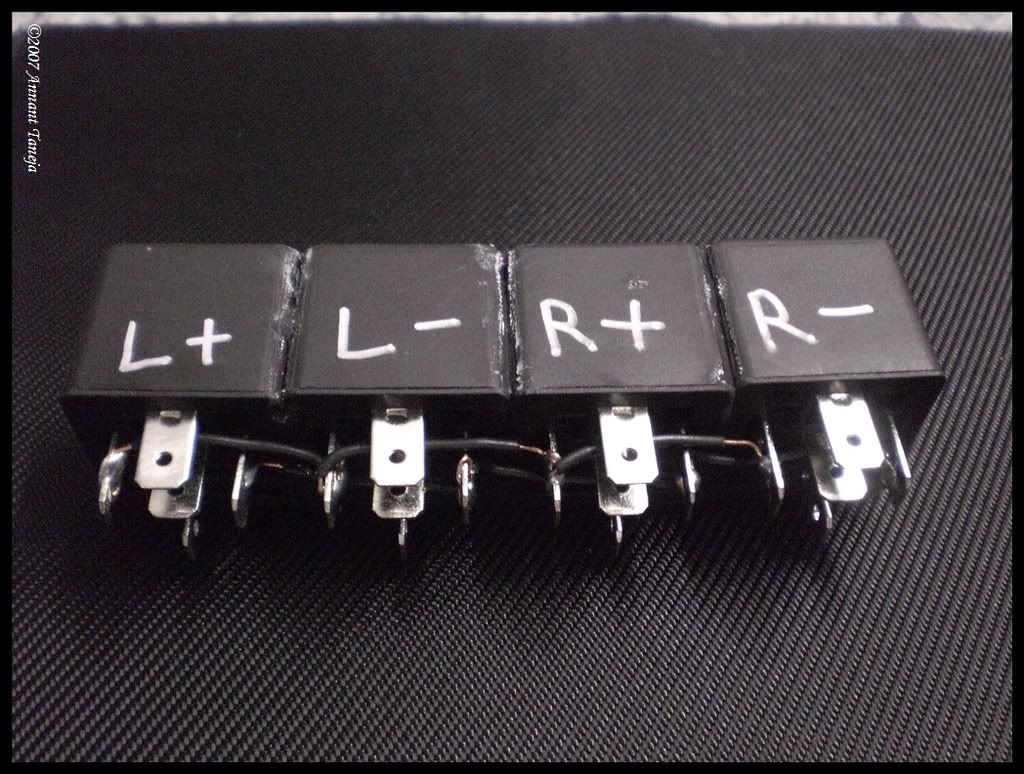
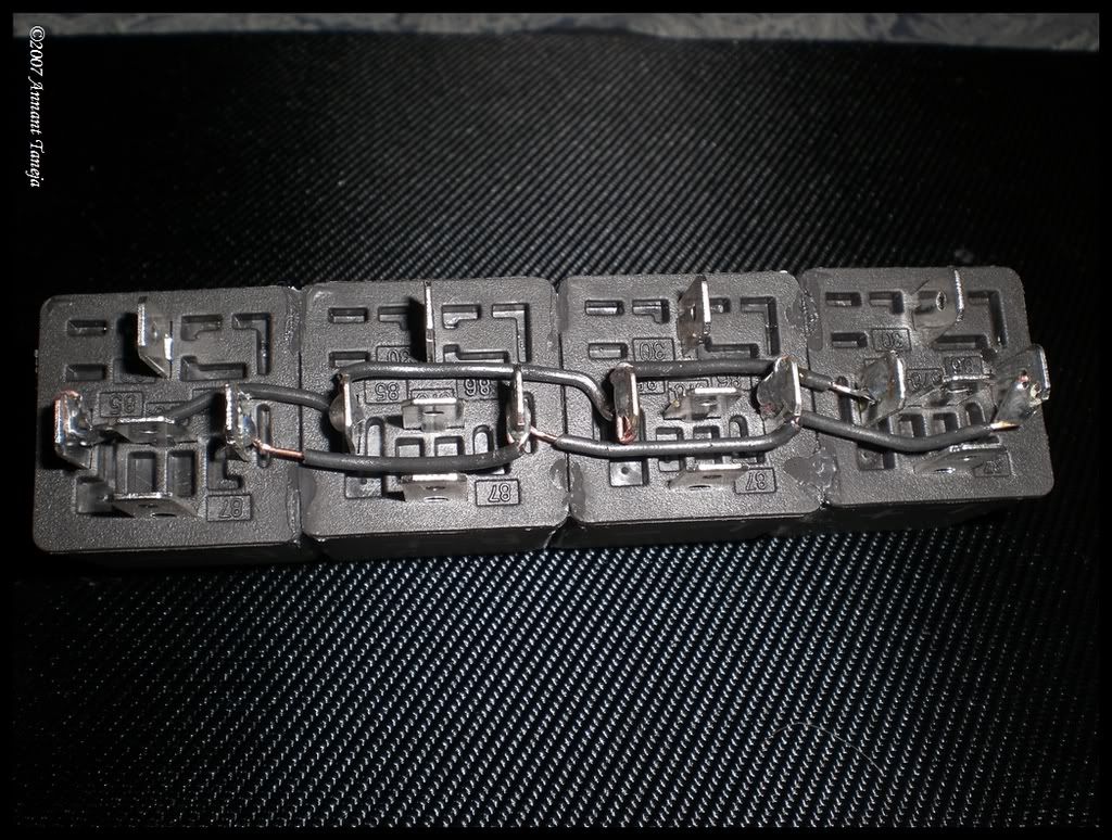
first thing u need to do is bind/connect/glue 4 of ur SPDT relays together so that the 86 and 85 poles are back to back as in the next image (which is upside down) Also labelling the relays makes later steps MUCH simpler.
Step 2.
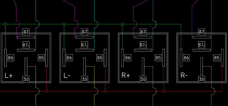
This is where the soldering skills come in handy, you need to connect all 4 relays in parallel (shown below) so that they energize at the same time.
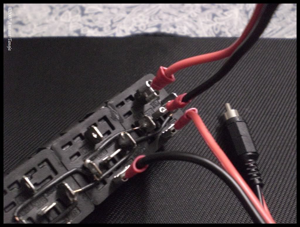
Step 3.
Connect the RCA tipped wires to the 87 Terminals on your relays. in this case, the red rca is right and the black is left, with red and black being + and - respectively.
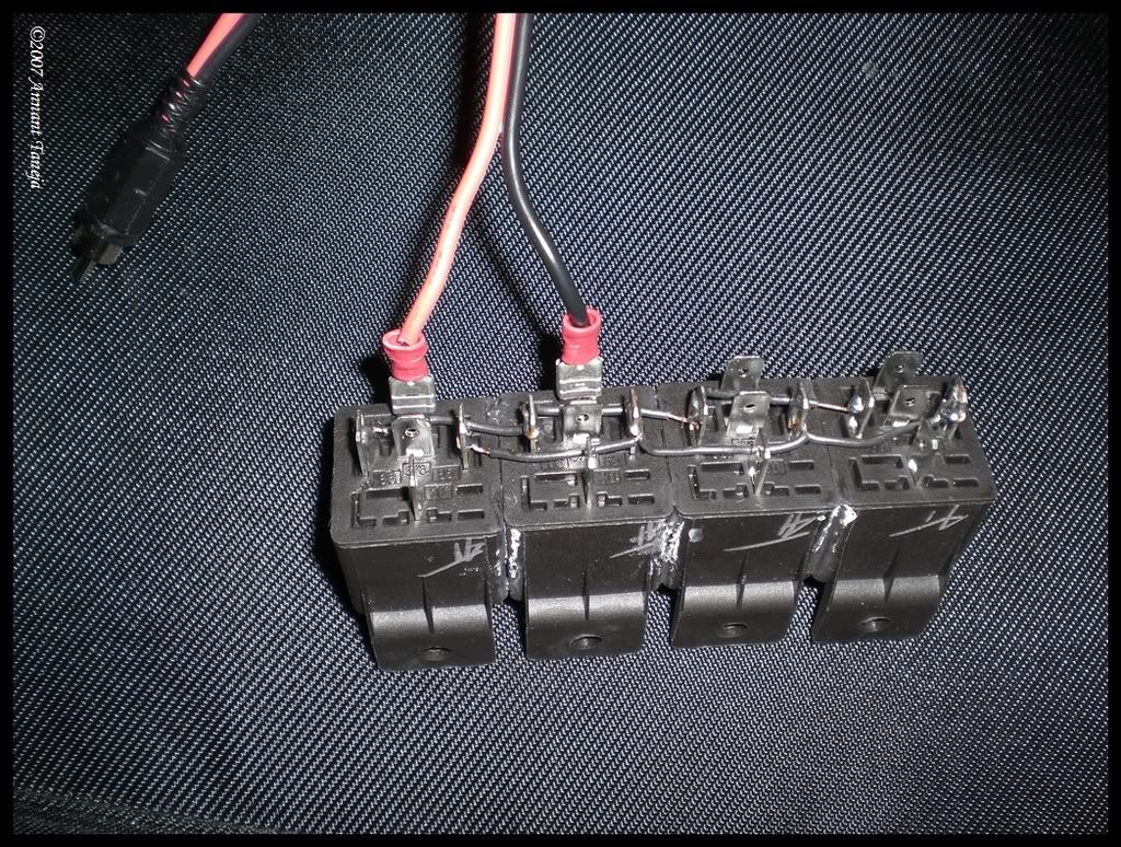
Step 4.
continuim to B-Cut 4 pieces of speaker wire (8 wires) approx 10-16in long. stip both ends and on one end of each crimp on a pair of female spade connectors. leave the other ends bare for now, they will get butt connectors later.
Step 5.
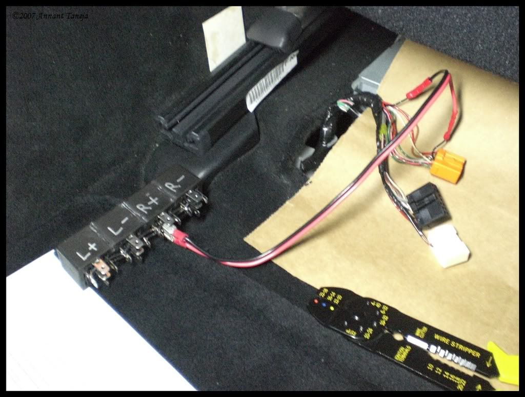
take 1 of the wires you just made, and connect the red to the 30 terminal on the L+ relay, its the one that is sideways to the rest. Then connect the black wire to the 87A termina, the one directly in the middle.
6.Repeat step 5 with the next relay. in this case it was L-
at this point you should have this.
here is ONE channel, ie LEFT in this case, completed.
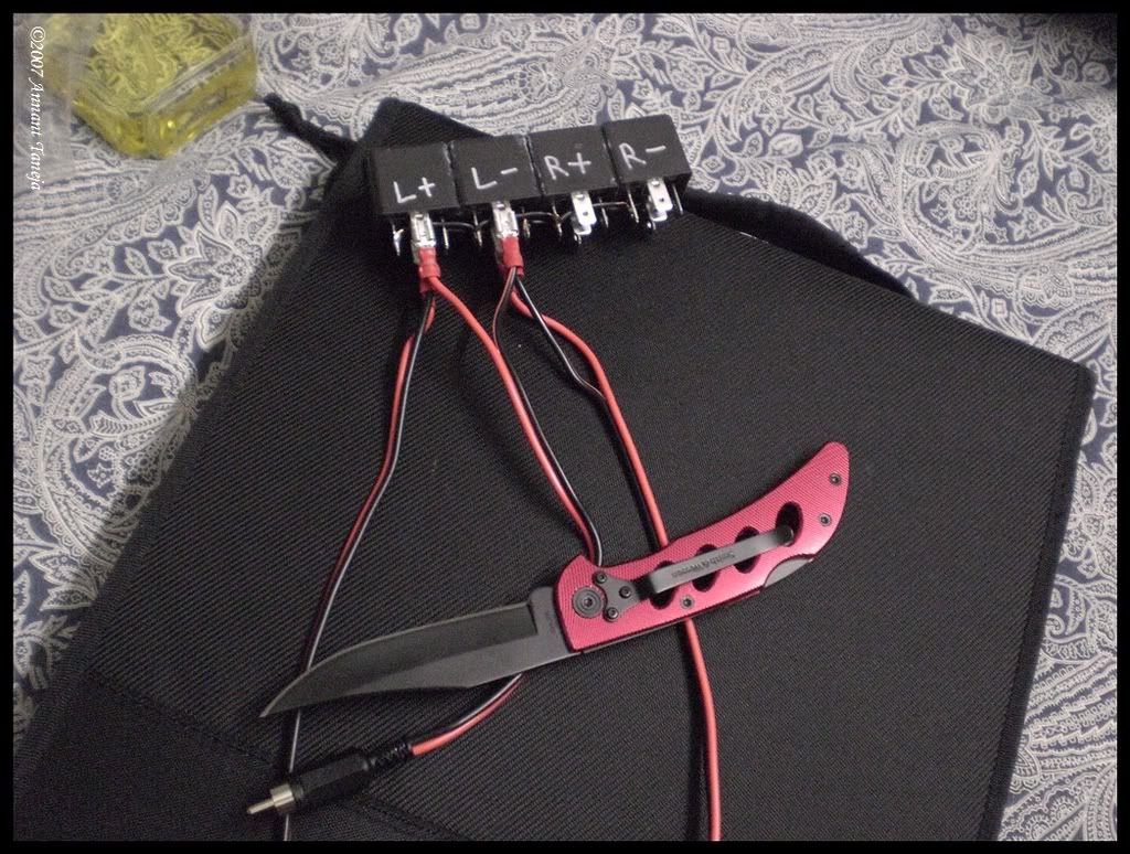
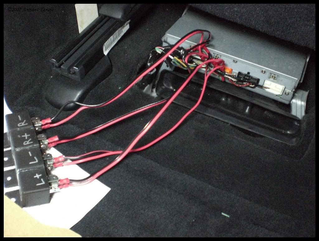
7. repeat Step 5. two more times for R+ and R-
now you have this:
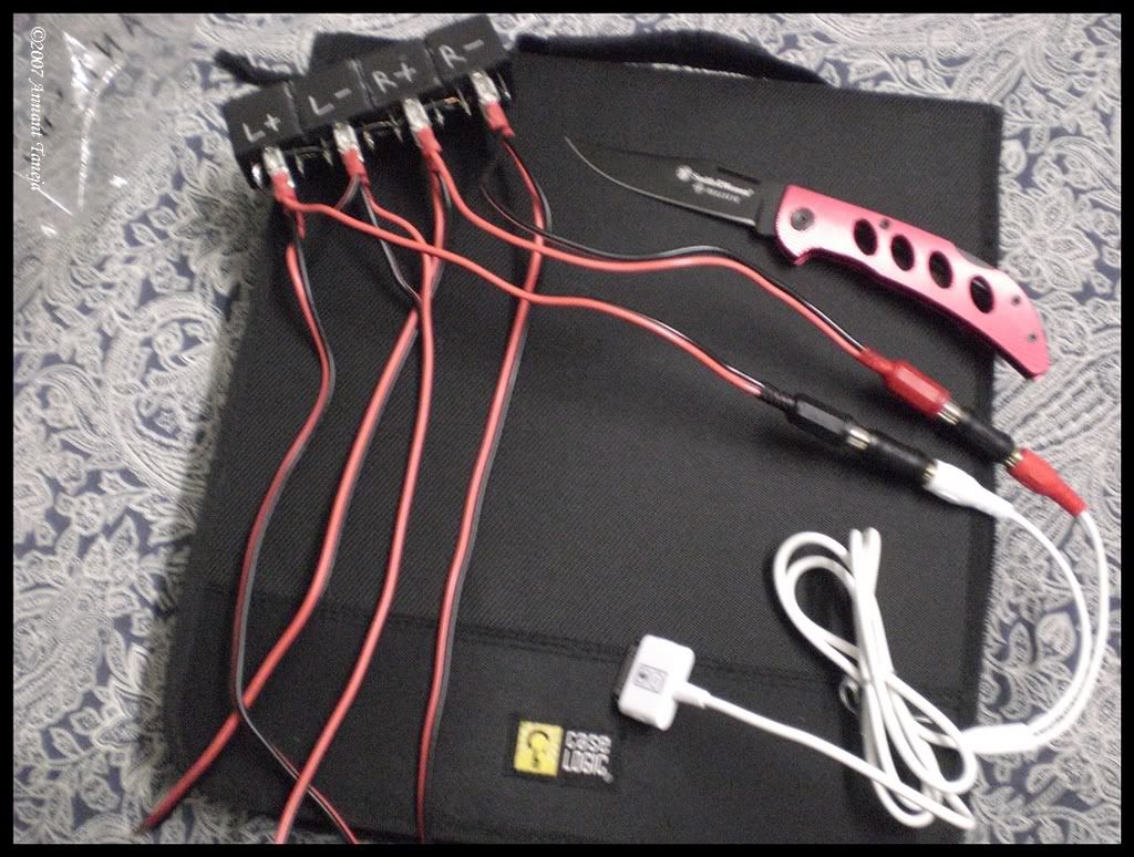
(^shown with RCA adapters and iPod cable attached)
part 3 coming soon
A-cut 4 pieces of 18ga. speaker wire to approx 10-16in. (thats 4pieces meaning 8 ind. wires) and strip both ends, attaching female spade connectors to one side only. the other sides leave bare since these are what we will be connecting the factory headunit/amp lines to using butt connectors.
for reference, the Red wires will be going INTO the Amplfier (headunit on some models) and the black will be coming FROM the CD changer.
B-cut and strip 2 more pieces (4 strands) of speaker wire (can be shorter, mine were approx 9-10 in.). on one end connect 4 female spade connectors. on the other end (should be bare at this point) you will connect/solder on your RCA terminals. remember when doing this that in an RCA cable, the center is positive and the outside is negative.
*pic coming soon*
Step 1.
first thing u need to do is bind/connect/glue 4 of ur SPDT relays together so that the 86 and 85 poles are back to back as in the next image (which is upside down) Also labelling the relays makes later steps MUCH simpler.
Step 2.
This is where the soldering skills come in handy, you need to connect all 4 relays in parallel (shown below) so that they energize at the same time.
Step 3.
Connect the RCA tipped wires to the 87 Terminals on your relays. in this case, the red rca is right and the black is left, with red and black being + and - respectively.
Step 4.
continuim to B-Cut 4 pieces of speaker wire (8 wires) approx 10-16in long. stip both ends and on one end of each crimp on a pair of female spade connectors. leave the other ends bare for now, they will get butt connectors later.
Step 5.
take 1 of the wires you just made, and connect the red to the 30 terminal on the L+ relay, its the one that is sideways to the rest. Then connect the black wire to the 87A termina, the one directly in the middle.
6.Repeat step 5 with the next relay. in this case it was L-
at this point you should have this.
here is ONE channel, ie LEFT in this case, completed.
7. repeat Step 5. two more times for R+ and R-
now you have this:
(^shown with RCA adapters and iPod cable attached)
part 3 coming soon
Last edited by PureDrifter; 03-11-07 at 08:49 PM.
03-05-07, 05:30 PM
#3
Installing the relays into the harness (finally!!)
This is specific for a 95-00 LS400(w/o NAK) but the same basic idea encompasses the entire range of vehicles. the only differences will be which wires to cut, the location of the amp (or headunit/cd changer), and where u run ur power wire.
in the 95-00 LS400 the amp we are tapping is underneath the front passenger seat. we dont need to remove the seat to do this mod, just move it all the way forward and up.

using the flathead and philips screwdrivers, remove the 2 blanks from the AC duct under the seat, then remove the 2 screws and remove the duct itself.

this is what you should be looking at with the cover removed. say hello to your amplifier
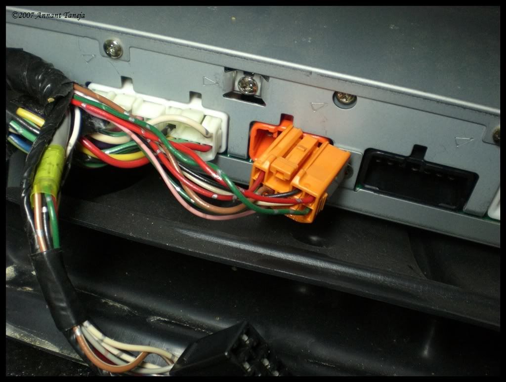
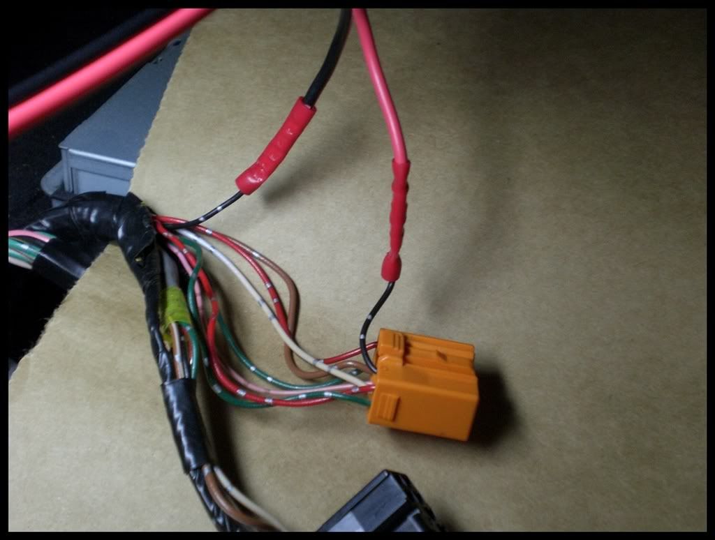
remove the right most black plug and the orange one next to it, this orange plug is the harness coming from the OEM cd changer, and, consequently, the one we are most interested in.
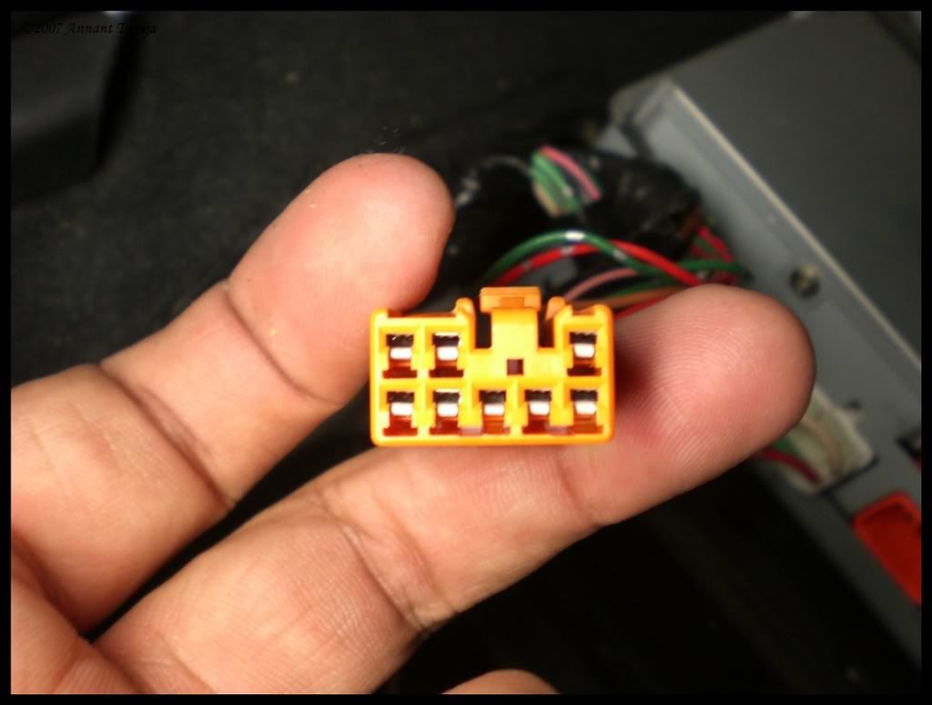
the plug numbers read like a book, top left is Pin no. 1, and then number across. bottom Left starts with Pin no. 4.
for the 98-00 LS w/o nak or navi these are the pins we intercept.
Pin__Color___Signal
2____black___CDR+
3____Red_____CDL+
5____White___CDR-
8____Green___CDL-
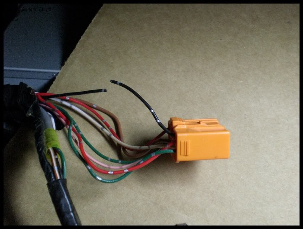
snip snip. best to do the cutting/crimping one wire at a time.
Black goes to harness and red goes into the amp/plug.
now you have this. see why labeling is a good idea...
now repeat the last couple steps for the rest of the signals and you ahve this.
This is specific for a 95-00 LS400(w/o NAK) but the same basic idea encompasses the entire range of vehicles. the only differences will be which wires to cut, the location of the amp (or headunit/cd changer), and where u run ur power wire.
in the 95-00 LS400 the amp we are tapping is underneath the front passenger seat. we dont need to remove the seat to do this mod, just move it all the way forward and up.
using the flathead and philips screwdrivers, remove the 2 blanks from the AC duct under the seat, then remove the 2 screws and remove the duct itself.
this is what you should be looking at with the cover removed. say hello to your amplifier
remove the right most black plug and the orange one next to it, this orange plug is the harness coming from the OEM cd changer, and, consequently, the one we are most interested in.
the plug numbers read like a book, top left is Pin no. 1, and then number across. bottom Left starts with Pin no. 4.
for the 98-00 LS w/o nak or navi these are the pins we intercept.
Pin__Color___Signal
2____black___CDR+
3____Red_____CDL+
5____White___CDR-
8____Green___CDL-
snip snip. best to do the cutting/crimping one wire at a time.
Black goes to harness and red goes into the amp/plug.
now you have this. see why labeling is a good idea...
now repeat the last couple steps for the rest of the signals and you ahve this.
Last edited by PureDrifter; 03-24-08 at 02:32 AM.
 03-05-07, 09:06 PM
#5
Lexus Test Driver

Beautiful job man!! 
It does work on the 1SC-- (=confirmed) -- However, a signal/line driver may be desired if your mp3 player's output doesn't match the gain of the CD changer source-- (Mine doesn't) Ipods are louder than my olympus player (500i -- 20g -- full color touchscreen)-- So ipods may be fine without a signal driver inline--
This is a very good mod by the way-- I will also be testing what signals the head unit needs to switch to cd w/o the changer present at all-- (not sure how that'll go yet, but hopefully well) .. It may be that all the h/u needs is a certain resistance on one pair to think the changer is there and powered up--
03-06-07, 05:50 AM
#6
Why not just use a 4 pole double throw relay? I've personally used this tons of times in the past, much cleaner install, less wiring, less chance of failure. Every relay will need 12v & ground of some sort. Why add wiring when you don't need to? You'll probably pay slightly more for the 4 pole relay, but it's worth it. This will work on any CD changer or any audio source for that matter as long as you can tap into the pre-amp level inputs...

Good info. for the board though...
Good info. for the board though...
The following users liked this post:
joetee (11-11-22)
03-06-07, 11:46 AM
#7
4pdt relays will work but the issue is finding them to work with 12v. i looked and found them after a while but the place only sold in bulk
the plus with using SPDT relays is that they are VERY commonly available.
why arent the pics showing up?? must find a new host now
the plus with using SPDT relays is that they are VERY commonly available.
why arent the pics showing up?? must find a new host now
Trending Topics
03-06-07, 12:06 PM
#8

If the mods don't mind me posting as i find this link pretty useful for the thread, though it is ebay, these are pretty good prices. Then again i dont know much when it comes to electronics.
http://cgi.ebay.com/Aromat-NF4EB-12V...hippingPayment
So they would run about 10 bucks shipped anywhere in the US.
Moderator Edit: ebay link may not work long-term.
http://cgi.ebay.com/Aromat-NF4EB-12V...hippingPayment
So they would run about 10 bucks shipped anywhere in the US.
Moderator Edit: ebay link may not work long-term.
Last edited by engin_ear; 03-19-07 at 01:36 PM.
03-06-07, 02:43 PM
#9
actually i wouldnt reccomend that unless u have a decent bit of experience working with PC mount relays. the pins are TINY and pretty impractical unless u plan on mounting it on a PCB.
that was another isssue i had with 4PDT relays - they are mostly PC mount only.
that was another isssue i had with 4PDT relays - they are mostly PC mount only.
03-11-07, 08:52 PM
#12
procedures are up
next update will be prolly in a week or so. it will be a step by step installation ( in this case in my Dad's LS)
also, let me make it clear. I AM NOT SELLING THIS.
i have matierals enoughh for 1-2 more ppl and they have contacted me during the development phase of my little project.
If, however, there is enough demand AND the CL Admin/Moderators don't mind there is possibility to change that.
Donations are accepted to help cover the cost of development
pm me for email
Last edited by PureDrifter; 03-11-07 at 08:58 PM.
03-11-07, 10:13 PM
#14
Driver School Candidate

Join Date: Mar 2007
Location: FL
Posts: 29
Likes: 0
Received 0 Likes
on
0 Posts
This looks awesome man. I can't wait to try this myself. I'm a complete newb to wiring and such so I have a couple questions. Is a B-Cut just stripping the protection away from the wires themselves? And on the 4 SPDT relays, did you just sodder all the 85s together and all the 86's together.
Also, where can an "iPod dock to RCA output cable" be purchased?
Great job doing this and great pictures btw.
*two thumbs up*
Also, where can an "iPod dock to RCA output cable" be purchased?
Great job doing this and great pictures btw.
*two thumbs up*

