
2jzGTE SCs - The Siblings of my Supra MKIV Toys
 01-03-14 | 01:14 PM
#1981
 I am about ready to purchase my aristo 2jzgte and would love not to spend $1000 on the harness work...Please create a new thread to document....Will you be combining the aristo harness with the sc300 harness?
01-03-14 | 01:19 PM
I am about ready to purchase my aristo 2jzgte and would love not to spend $1000 on the harness work...Please create a new thread to document....Will you be combining the aristo harness with the sc300 harness?
01-03-14 | 01:19 PM
#1982

Thread Starter
Super Moderator
iTrader: (34)
Joined: May 2009
Posts: 6,135
Likes: 432
From: A Mile Ahead of You
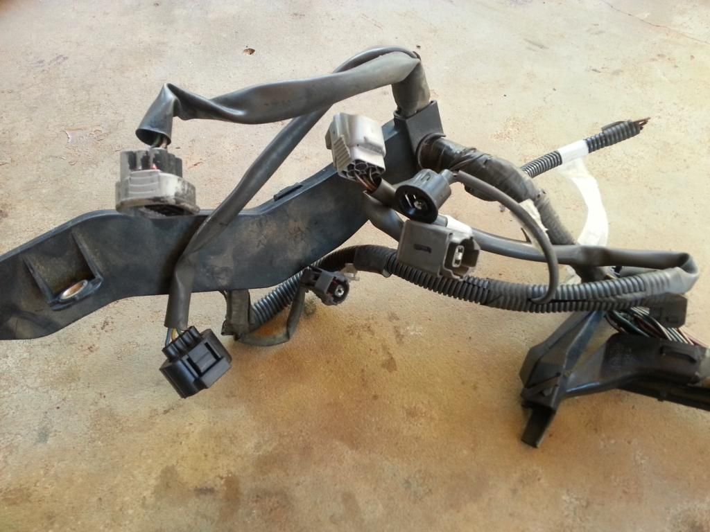
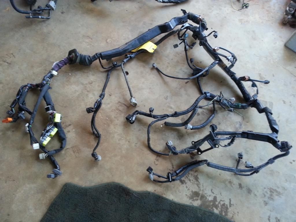
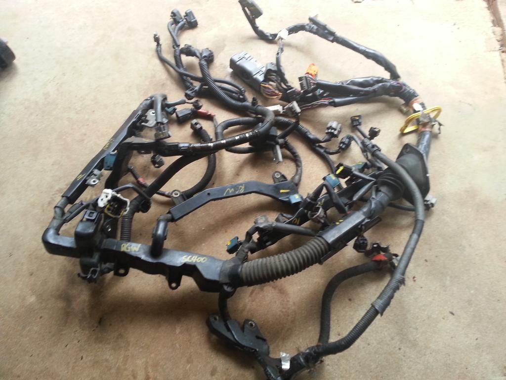
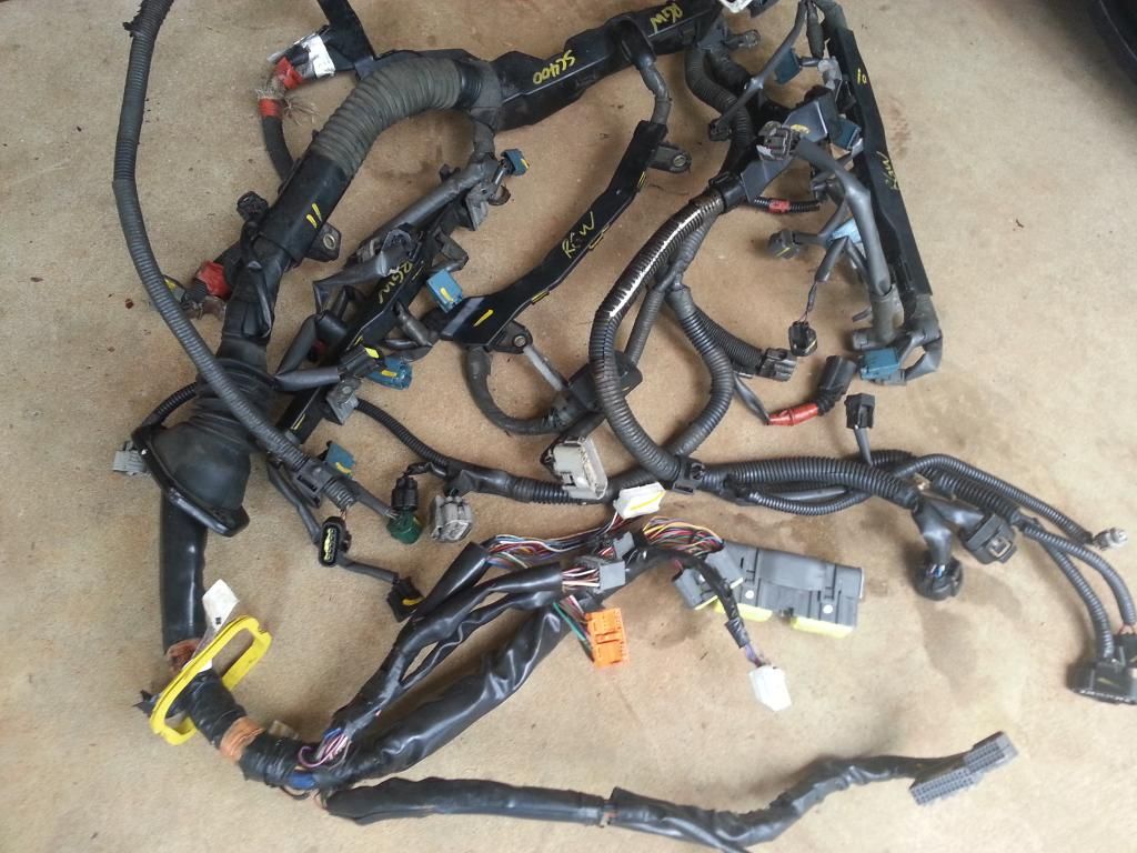
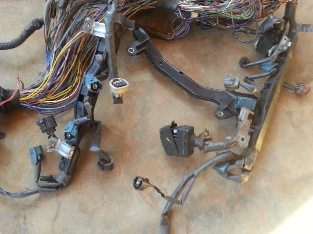
Here is a detailed picture of an Aristo 2jzgte harness that comes with the engine swap you will get.
Whole uncut harness
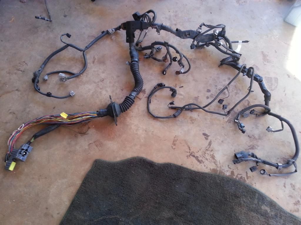
The following pictures are close-up pictures of the uncut harness
80 pin harness with the Big Gray Body Plug
They normally come with auto transmissions so they have the plugs / wiring to control the transmission.
Injectors , Cam sensors , IACV , Map and Air Temp sensors connectors
#1 injector , TPS , sub-tps , oil pressure sensor , knock sensor , throttle motor valve , Ground Front Side of Intake Manifold connectors
Coils, VSVs connectors
Igniter , noise filter , crank , coolant temp , coolant gauge sender and VSV connectors
Diagnostic port , knock , starter , ground connectors
Whole uncut harness

The following pictures are close-up pictures of the uncut harness
80 pin harness with the Big Gray Body Plug

They normally come with auto transmissions so they have the plugs / wiring to control the transmission.

Injectors , Cam sensors , IACV , Map and Air Temp sensors connectors

#1 injector , TPS , sub-tps , oil pressure sensor , knock sensor , throttle motor valve , Ground Front Side of Intake Manifold connectors

Coils, VSVs connectors

Igniter , noise filter , crank , coolant temp , coolant gauge sender and VSV connectors

Diagnostic port , knock , starter , ground connectors

Last edited by gerrb; 08-10-17 at 05:43 PM.
01-03-14 | 01:32 PM
#1983
Thread Starter
Super Moderator
iTrader: (34)
Joined: May 2009
Posts: 6,135
Likes: 432
From: A Mile Ahead of You
Since it is easy to get the posts that are related to the 2jzgte SC harness build (They are titled " Non VVTi 2jzgte Lexus SC Engine Harness Build - Post # xxx ") , we can extract them from this thread once it is all done and put them in one thread if you like. If it will be helpful to others , why not.
Whether it is an Aristo harness with SC300 or SC400 , the info that will be written here will basically be the same. There will be minor differences only since the body plugs of both SC300 and SC400 are almost the same and their 40 pin connector has a lot in common in terms of pinouts . I will point out differences since the first I did was an SC400 on my RM1 and now it is for an SC300 on my RM2 and two of my buddies here.
Last edited by gerrb; 01-04-14 at 09:26 AM.
01-03-14 | 01:36 PM
#1984
Sounds like a plan man. Put that bottle down and get some wiring done. Please for the love of GOD, get a better quality camera. Oh wait a minute, you are moving too much from your drunkenness. Be sober and take better quality pictures. Don't make me come down there. LOL
01-03-14 | 01:51 PM
#1985
Thread Starter
Super Moderator
iTrader: (34)
Joined: May 2009
Posts: 6,135
Likes: 432
From: A Mile Ahead of You
I have been making margarita with the bottle of patron given to me since midnight of Jan. 1.. lol.
 01-03-14 | 01:55 PM
#1986
The Note 2 and 3, which I have, are great picture taking cameras. You need to touch the screen so it can focus before you take the picture. LOL..
Those look great. Its 5 o'clock somewhere. Old military saying.
Those look great. Its 5 o'clock somewhere. Old military saying.
01-03-14 | 02:00 PM
#1987
Thread Starter
Super Moderator
iTrader: (34)
Joined: May 2009
Posts: 6,135
Likes: 432
From: A Mile Ahead of You
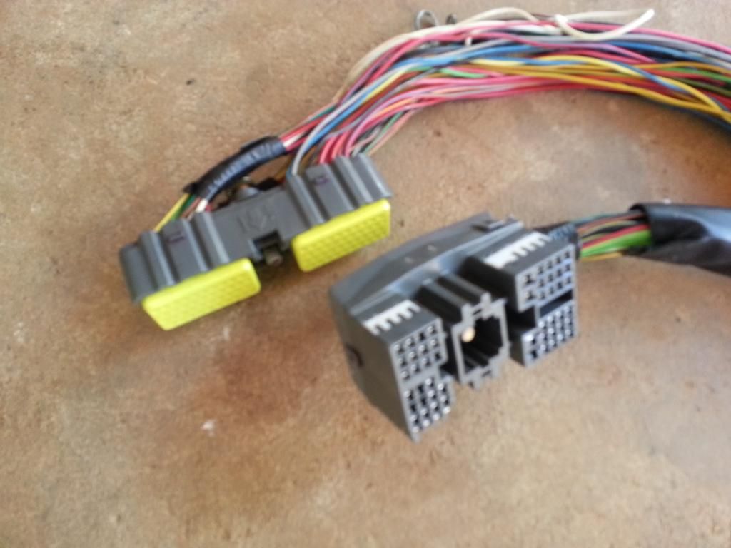
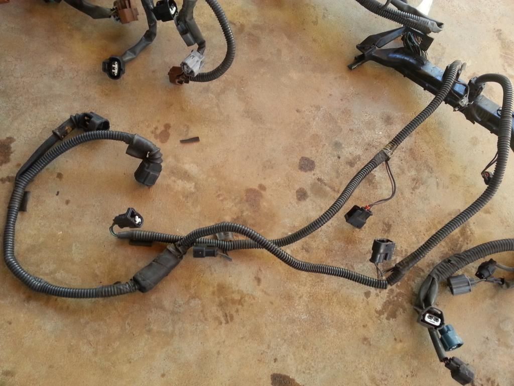
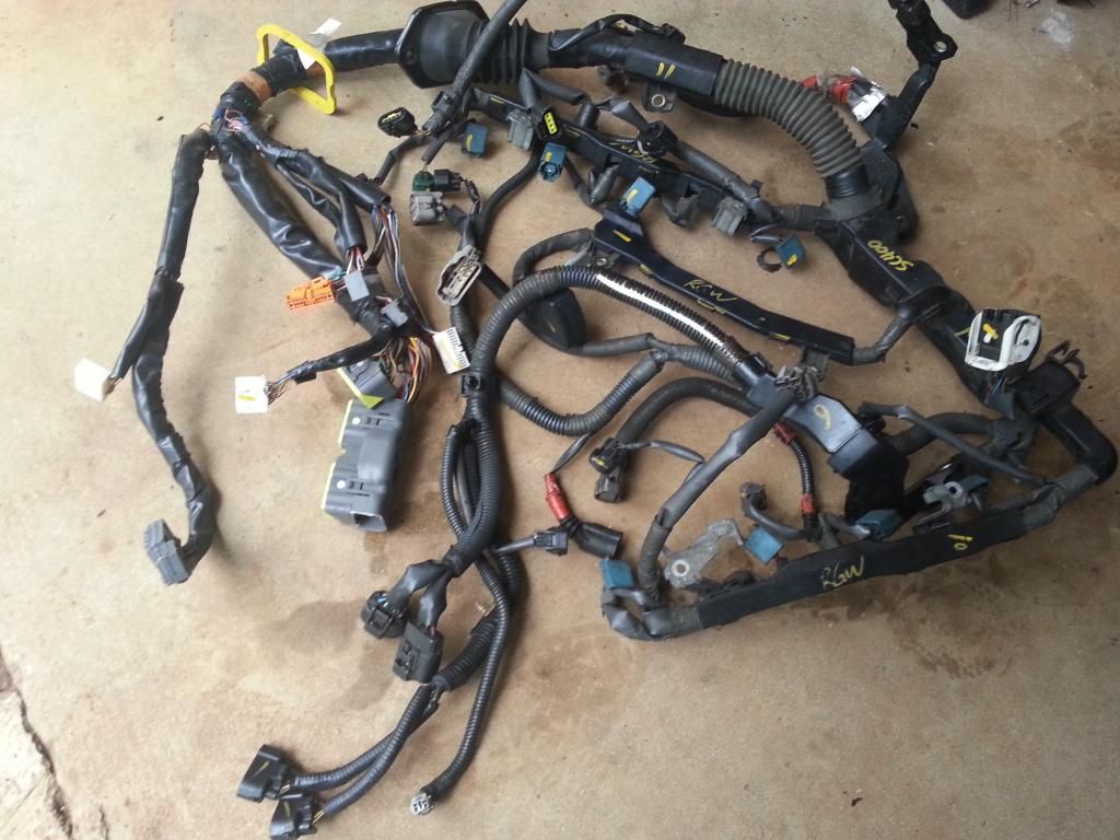
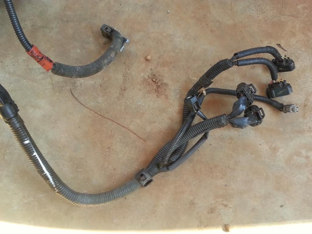
This is a picture of your SC300 harness.
80 pin connector , 40 pin connector and the body plugs
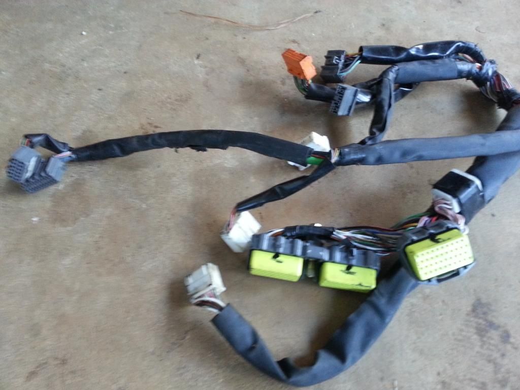
This harness had the auto transmission connectors .
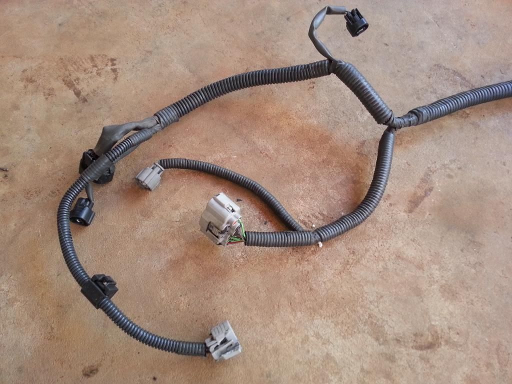
Here you see the injectors , knock sensor connectors
You got the diagnostic port , ground , knock sensor connectors
Those two big connectors you find front lower part of your fusebox.
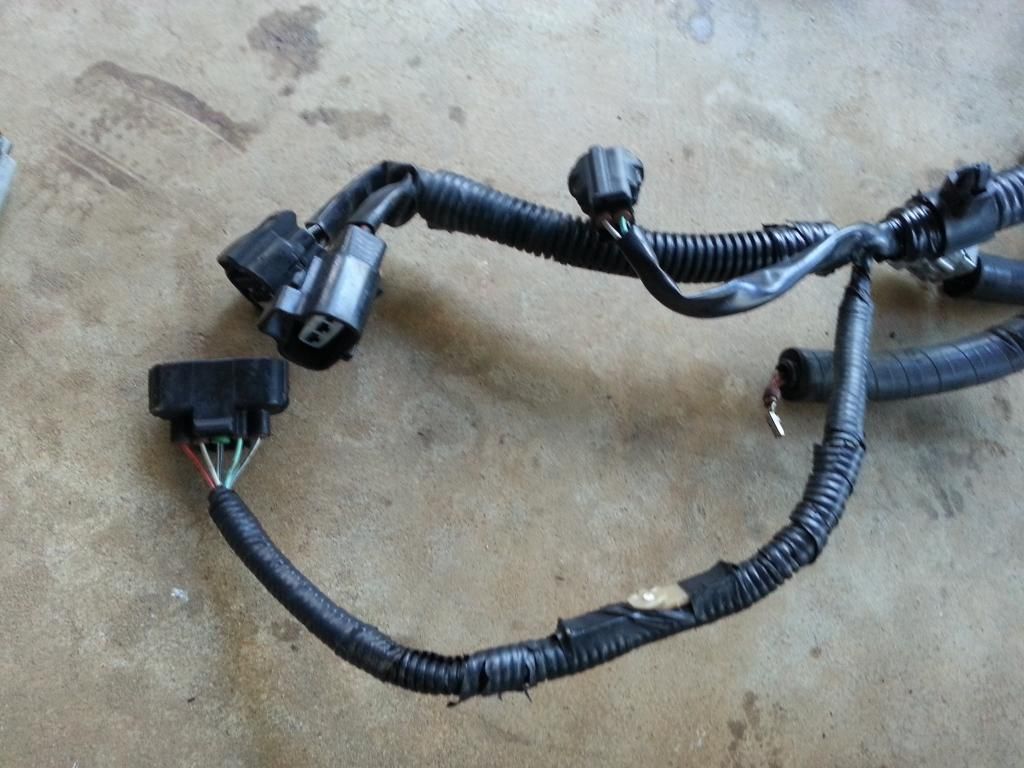
Coil, filter , igniter , tps , coolant connectors

80 pin connector , 40 pin connector and the body plugs

This harness had the auto transmission connectors .

Here you see the injectors , knock sensor connectors

You got the diagnostic port , ground , knock sensor connectors

Those two big connectors you find front lower part of your fusebox.

Coil, filter , igniter , tps , coolant connectors

Last edited by gerrb; 01-19-14 at 07:59 AM.
01-03-14 | 02:10 PM
#1988
Thread Starter
Super Moderator
iTrader: (34)
Joined: May 2009
Posts: 6,135
Likes: 432
From: A Mile Ahead of You
Hehe, I really don't drink much. Every now and then , when there is an occasion , I get drunk...lol.. But one thing I know , Rey (PogikoSC4) one day got me drunk at Hooters..
 .
.
Last edited by gerrb; 01-03-14 at 05:54 PM.
01-03-14 | 02:29 PM
#1989
Thread Starter
Super Moderator
iTrader: (34)
Joined: May 2009
Posts: 6,135
Likes: 432
From: A Mile Ahead of You
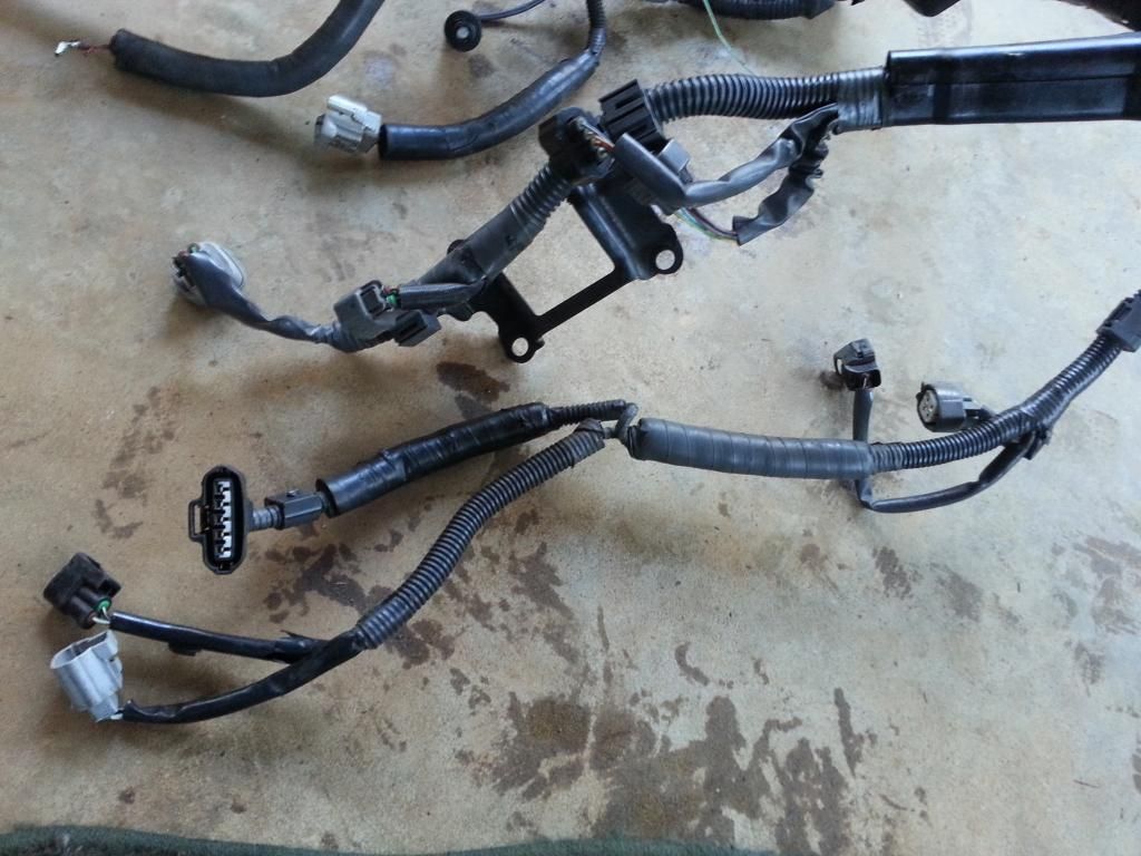
I don't have new pictures of an SC400 harness. These I took for someone here some time back. This harness is from a 1992 SC400 with auto transmission. BTW , no USDM SC400 came out with manual transmission from the factory.
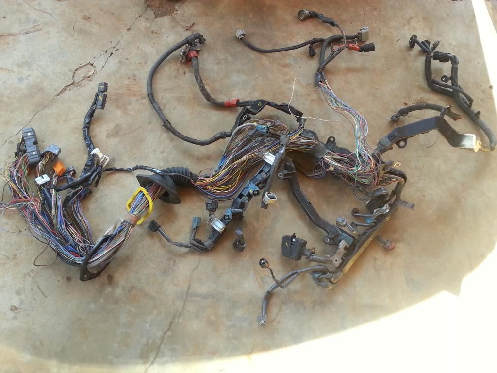
Observe the 80 pin, 40 pin and most of the body plugs . Don't they look similar with that of the SC300 ?
So what are these 80 pin and 40 pin connectors for ? They are actually the connectors to the ECU. They link your engine components , sensors to your Engine ECU whether it is a 2jzge , 1uzfe or your new 2jzgte.
What are the body plugs for ? The body plugs connect the engine components , sensors or ECU to your dashboard cluster or other components of your car .
IF you look back , the Aristo , SC300 , SC400 harness have all one thing in common , the 80 pin connector . Take note though that not all of them have same pin configuration. What does that mean ? Not all pins are used in the same manner by all of those three harnesses. Let's say pin 6 may be used differently by the other. They also have different body plugs though the SC300 and SC400 have similar ones but again may have different pin configurations.
SC400 injectors , diagnostic port , IACV , etc
Big plugs you see on the SC400 lower front fuse box
Auto transmission connectors
O2 sensor connector
I will leave the Supra MKIV wiring harness out of the picture now . I just want to let people know that not because you bought a MKIV TT 2jzgte harness (whether for auto or manual) , it will work with our SC300 or SC400 2jzgte swaps. They have different body plugs . They would not work without any modifications on them meaning you have to remove the plugs distinct to the MKIV and incorporate some plugs (like body plugs) that are distinct to our SC300 / SC400 cars.


Observe the 80 pin, 40 pin and most of the body plugs . Don't they look similar with that of the SC300 ?
So what are these 80 pin and 40 pin connectors for ? They are actually the connectors to the ECU. They link your engine components , sensors to your Engine ECU whether it is a 2jzge , 1uzfe or your new 2jzgte.
What are the body plugs for ? The body plugs connect the engine components , sensors or ECU to your dashboard cluster or other components of your car .
IF you look back , the Aristo , SC300 , SC400 harness have all one thing in common , the 80 pin connector . Take note though that not all of them have same pin configuration. What does that mean ? Not all pins are used in the same manner by all of those three harnesses. Let's say pin 6 may be used differently by the other. They also have different body plugs though the SC300 and SC400 have similar ones but again may have different pin configurations.

SC400 injectors , diagnostic port , IACV , etc

Big plugs you see on the SC400 lower front fuse box

Auto transmission connectors

O2 sensor connector

I will leave the Supra MKIV wiring harness out of the picture now . I just want to let people know that not because you bought a MKIV TT 2jzgte harness (whether for auto or manual) , it will work with our SC300 or SC400 2jzgte swaps. They have different body plugs . They would not work without any modifications on them meaning you have to remove the plugs distinct to the MKIV and incorporate some plugs (like body plugs) that are distinct to our SC300 / SC400 cars.
Last edited by gerrb; 01-20-14 at 03:07 AM.
01-03-14 | 03:52 PM
#1990
Thread Starter
Super Moderator
iTrader: (34)
Joined: May 2009
Posts: 6,135
Likes: 432
From: A Mile Ahead of You
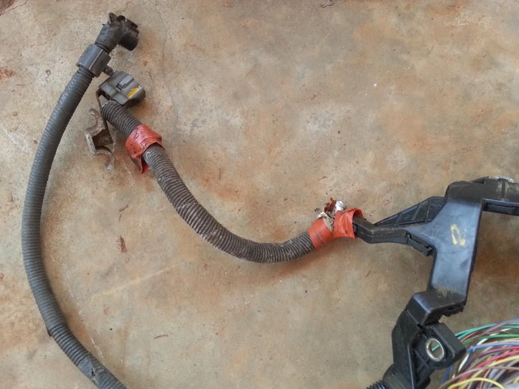
Let me go back on the Aristo 2jzgte harness which you got with your 2jzgte swap . I will always start with this harness as my base . Why ? Most of the major plugs / wiring needed to run your engine is already there , done for you. They are already installed in the right places.
Before unwrapping your harness , take note of the diameter or size of the wrapped wires. WHY ? The firewall hole on the passenger side is not that big. Whatever you do on that harness make sure that you will still be able to insert it into that hole going to the passenger footwell. This will be more important when you lengthen those wires and do soldering and shrink wrapping. The wrapped harness becomes bigger.

Remember it is a 2jzgte harness already though for an aristo car and not SC300 / SC400. So truly all you need to do is replace that big gray aristo body plug with all the body plugs and 40 pin connector of the SC300 / SC400 .
Try to recall for a moment what I previously said about the body plugs and 40 pin connector . The 40 pin connector will house some of the pins needed to get your car running . Like many of the auto transmission wiring go to that connector and the body plugs are used to connect your engine components and ecu to the components in your car like cluster , switches , gauges , etc.
BEFORE WE GO AHEAD , let me warn you , CLEANLINESS or ORDERLINESS is very important. Do things in small phases. IF you are not sure you won't be confused , don't try to unwrap all covers or tapes of your harness. I have seen some who have unwrapped everything at once and all wires got messed up and gave up due to the confusion and the harness becoming a ball of messed wires.
Let me assume some things here .
A) You have and know how to use the multi-tester or ohmmeter or connectivity probe / analyzer to check connections between two or more points.
B) You have the simple tools needed like soldering iron or gun , screw drivers , wire cutter / splicer , etc.
C) You have the supplies necessary that goes with your tools like soldering paste , soldering wire , heat shrink , etc.
Let me introduce here what I call "THE DRILL" .
A) Decide if you need the plug and wires depending on your particular setup .
..A1) IF YES ( that means you are keeping the plug ) , then
......A1a) Inspect the connector (plug) if it is physically damaged
......A1b) Replace that plug if its casing or lock is broken
......A1c) Go through all the wires of that plug
.........A1c1) Trace the wire by finding the pin from the plug where it goes to
............A1c11) If the wire ends at the 80 pin ECU connector OR Other Plug (except Big Gray Aristo Plug) then leave it where it is. That is where it should be anyway.
............A1c12) If the wire ends at the Big Gray Aristo Plug then pull it out from there and label it..
.........A1c2) If the wire ends at the 80 pin ECU connector OR Big Gray Aristo Plug then EXTEND IT otherwise you are not extending the wire.
.........A1c3) If the wire had been extended then Heat Shrink Wrap those solder points ( make sure no strand of wire is out of that heat shrink )
.........A1c4) Check connectivity between the two end points for that particular wire which you have just extended.
......A1d) Cover the wires of the plug with electrical tape and corrugated flexible hose once you are done with every single wire on that plug.
...A2) IF NO ( that means you are NOT keeping the plug ) and YOU ARE NOT KEEPING THE WIRES for future needs then start pulling the plug and its wires out
...A3) IF NO ( that means you are NOT keeping the plug ) BUT YOU ARE KEEPING THOSE WIRES for other components
......A3a) Remove the stock connector
......A3b) Extend the wires you are keeping and pull out the wires you do not need.
......A3c) Heat Shrink Wrap those solder points ( make sure no strand of wire is out of that heat shrink )
......A3d) Check connectivity between the two end points for that particular wire which you have just extended.
......A3e) Label the wire on both ends so you know it is an extra wire and which end point goes to the other end point
B) Update your CHART .
You have to know that drill really well by heart .You will do it many times on this 2jzgte harness build.
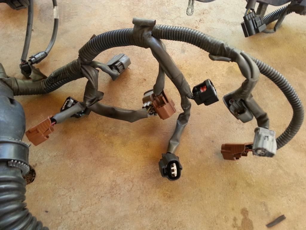
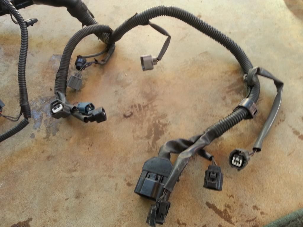
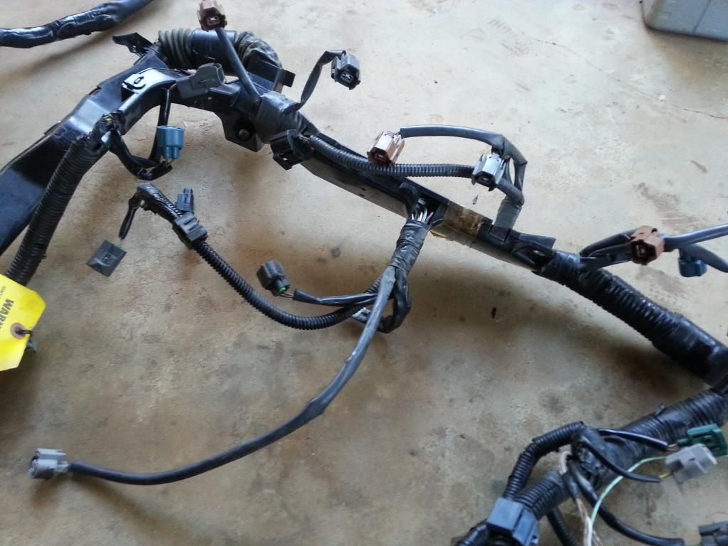
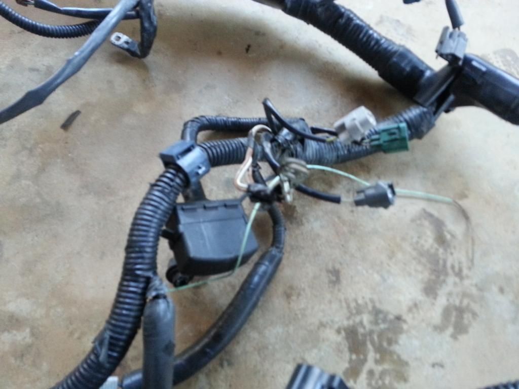
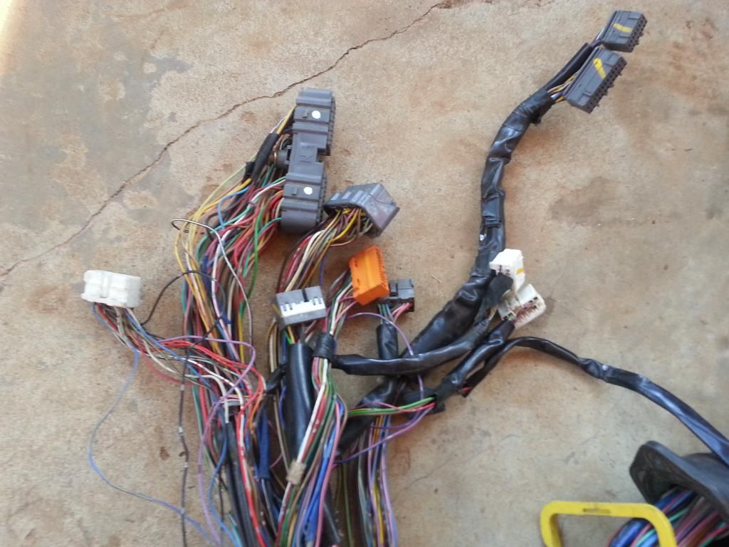
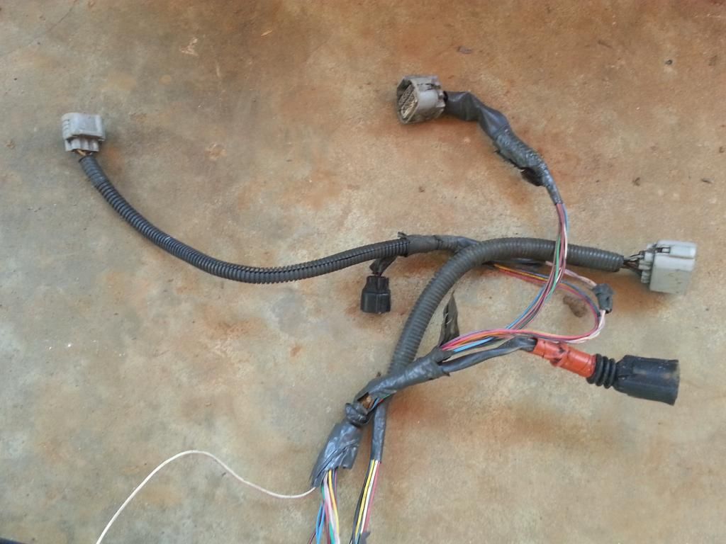
You need to inspect well your 2jzgte harness . How many plugs are broken or missing ? Most of them get brittle especially their locks. Make a list of what connectors you need to replace. You might need to buy some of them or get them from an extra harness you have. If you can get all those broken plugs and the wires you need for extending before you start the actual work then you can work continuously on the harness.
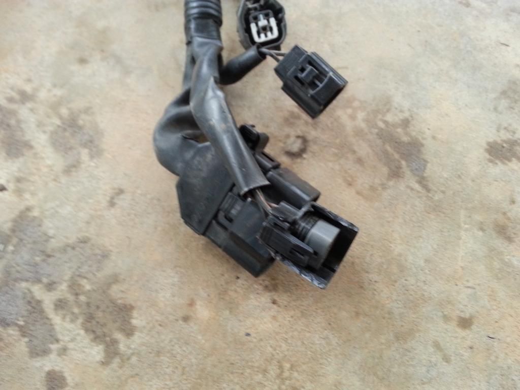
Here you see broken coil connectors.
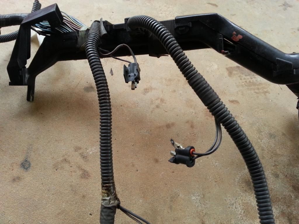
Injectors and cam connectors with broken locks
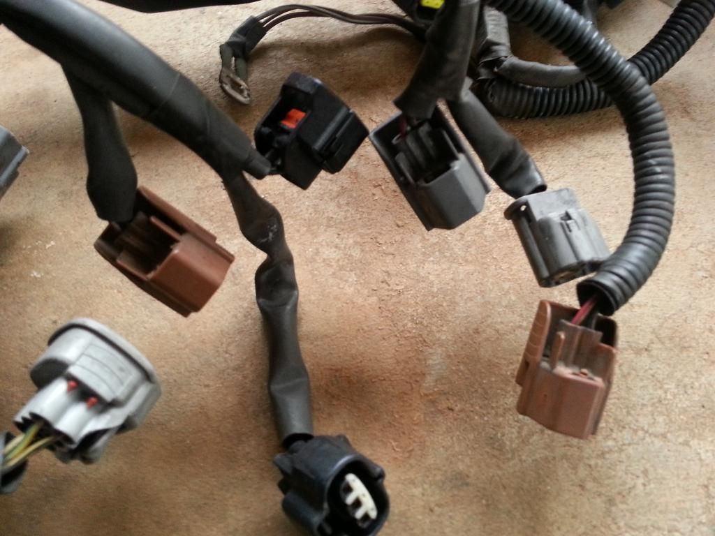
Another connector with a broken housing
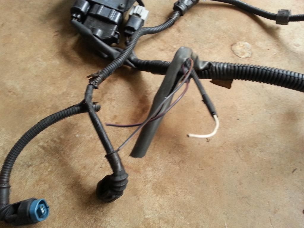
You got to identify all the wires that are broken or are not insulated . You don't want exposed wires and get shorts that can damage components or start a fire.
Broken / Cut wires
Once you have figured out what connectors need to be replaced and wires that are exposed , it is time to secure the parts you need so you can get the ball rolling.
With regards thickness of wires. ALWAYS use the same gauge (size) of wire or bigger. The amount of current (amperes) that goes through those wires have already been computed by Toyota. All you need is use at least same size of wire so you don't burn anything or start any engine bay fire with too much current going through the wires which causes the wires to heat up and eventually burn.
Also consider if you are using other set of injectors or aftermarket connectors for MAP , Air Intake Temp , Fuel & Oil Pressure , Coolant & Oil Temp and others. You need to get their pigtails or connectors so you can incorporate them into your harness.
Depending on your setup , like if you are going single turbo , some of the connectors on this harness like VSVs can be removed / deleted OR those wires can be used for other stuff you would include in your setup like AIT Sensor , Boost Solenoid . Just take note of the wiring sizes and use them accordingly meaning small wires can only carry small current so you can't use those wires for components that consume a lot of current. Remember what I just said regarding thickness of wires.
Before unwrapping your harness , take note of the diameter or size of the wrapped wires. WHY ? The firewall hole on the passenger side is not that big. Whatever you do on that harness make sure that you will still be able to insert it into that hole going to the passenger footwell. This will be more important when you lengthen those wires and do soldering and shrink wrapping. The wrapped harness becomes bigger.

Remember it is a 2jzgte harness already though for an aristo car and not SC300 / SC400. So truly all you need to do is replace that big gray aristo body plug with all the body plugs and 40 pin connector of the SC300 / SC400 .
Try to recall for a moment what I previously said about the body plugs and 40 pin connector . The 40 pin connector will house some of the pins needed to get your car running . Like many of the auto transmission wiring go to that connector and the body plugs are used to connect your engine components and ecu to the components in your car like cluster , switches , gauges , etc.
BEFORE WE GO AHEAD , let me warn you , CLEANLINESS or ORDERLINESS is very important. Do things in small phases. IF you are not sure you won't be confused , don't try to unwrap all covers or tapes of your harness. I have seen some who have unwrapped everything at once and all wires got messed up and gave up due to the confusion and the harness becoming a ball of messed wires.
Let me assume some things here .
A) You have and know how to use the multi-tester or ohmmeter or connectivity probe / analyzer to check connections between two or more points.
B) You have the simple tools needed like soldering iron or gun , screw drivers , wire cutter / splicer , etc.
C) You have the supplies necessary that goes with your tools like soldering paste , soldering wire , heat shrink , etc.
Let me introduce here what I call "THE DRILL" .
A) Decide if you need the plug and wires depending on your particular setup .
..A1) IF YES ( that means you are keeping the plug ) , then
......A1a) Inspect the connector (plug) if it is physically damaged
......A1b) Replace that plug if its casing or lock is broken
......A1c) Go through all the wires of that plug
.........A1c1) Trace the wire by finding the pin from the plug where it goes to
............A1c11) If the wire ends at the 80 pin ECU connector OR Other Plug (except Big Gray Aristo Plug) then leave it where it is. That is where it should be anyway.
............A1c12) If the wire ends at the Big Gray Aristo Plug then pull it out from there and label it..
.........A1c2) If the wire ends at the 80 pin ECU connector OR Big Gray Aristo Plug then EXTEND IT otherwise you are not extending the wire.
.........A1c3) If the wire had been extended then Heat Shrink Wrap those solder points ( make sure no strand of wire is out of that heat shrink )
.........A1c4) Check connectivity between the two end points for that particular wire which you have just extended.
......A1d) Cover the wires of the plug with electrical tape and corrugated flexible hose once you are done with every single wire on that plug.
...A2) IF NO ( that means you are NOT keeping the plug ) and YOU ARE NOT KEEPING THE WIRES for future needs then start pulling the plug and its wires out
...A3) IF NO ( that means you are NOT keeping the plug ) BUT YOU ARE KEEPING THOSE WIRES for other components
......A3a) Remove the stock connector
......A3b) Extend the wires you are keeping and pull out the wires you do not need.
......A3c) Heat Shrink Wrap those solder points ( make sure no strand of wire is out of that heat shrink )
......A3d) Check connectivity between the two end points for that particular wire which you have just extended.
......A3e) Label the wire on both ends so you know it is an extra wire and which end point goes to the other end point
B) Update your CHART .
You have to know that drill really well by heart .You will do it many times on this 2jzgte harness build.
You need to inspect well your 2jzgte harness . How many plugs are broken or missing ? Most of them get brittle especially their locks. Make a list of what connectors you need to replace. You might need to buy some of them or get them from an extra harness you have. If you can get all those broken plugs and the wires you need for extending before you start the actual work then you can work continuously on the harness.
Here you see broken coil connectors.

Injectors and cam connectors with broken locks

Another connector with a broken housing

You got to identify all the wires that are broken or are not insulated . You don't want exposed wires and get shorts that can damage components or start a fire.
Broken / Cut wires

Once you have figured out what connectors need to be replaced and wires that are exposed , it is time to secure the parts you need so you can get the ball rolling.
With regards thickness of wires. ALWAYS use the same gauge (size) of wire or bigger. The amount of current (amperes) that goes through those wires have already been computed by Toyota. All you need is use at least same size of wire so you don't burn anything or start any engine bay fire with too much current going through the wires which causes the wires to heat up and eventually burn.
Also consider if you are using other set of injectors or aftermarket connectors for MAP , Air Intake Temp , Fuel & Oil Pressure , Coolant & Oil Temp and others. You need to get their pigtails or connectors so you can incorporate them into your harness.
Depending on your setup , like if you are going single turbo , some of the connectors on this harness like VSVs can be removed / deleted OR those wires can be used for other stuff you would include in your setup like AIT Sensor , Boost Solenoid . Just take note of the wiring sizes and use them accordingly meaning small wires can only carry small current so you can't use those wires for components that consume a lot of current. Remember what I just said regarding thickness of wires.
Last edited by gerrb; 01-23-14 at 06:29 PM.
01-03-14 | 04:55 PM
#1991
Thread Starter
Super Moderator
iTrader: (34)
Joined: May 2009
Posts: 6,135
Likes: 432
From: A Mile Ahead of You
I am not sure if it is allowed here to post a link but the following info I extracted from this site ( http://wilbo666.pbworks.com/w/page/3...ngine%20Wiring)
BIG THANKS to the owners of that site for the info and if the link will be deleted because it is not allowed ,just do a google search "WILBO666 2jzgte" .
I am posting the info here so all info that may help you understand your 2jzgte harness better will all be in one place.
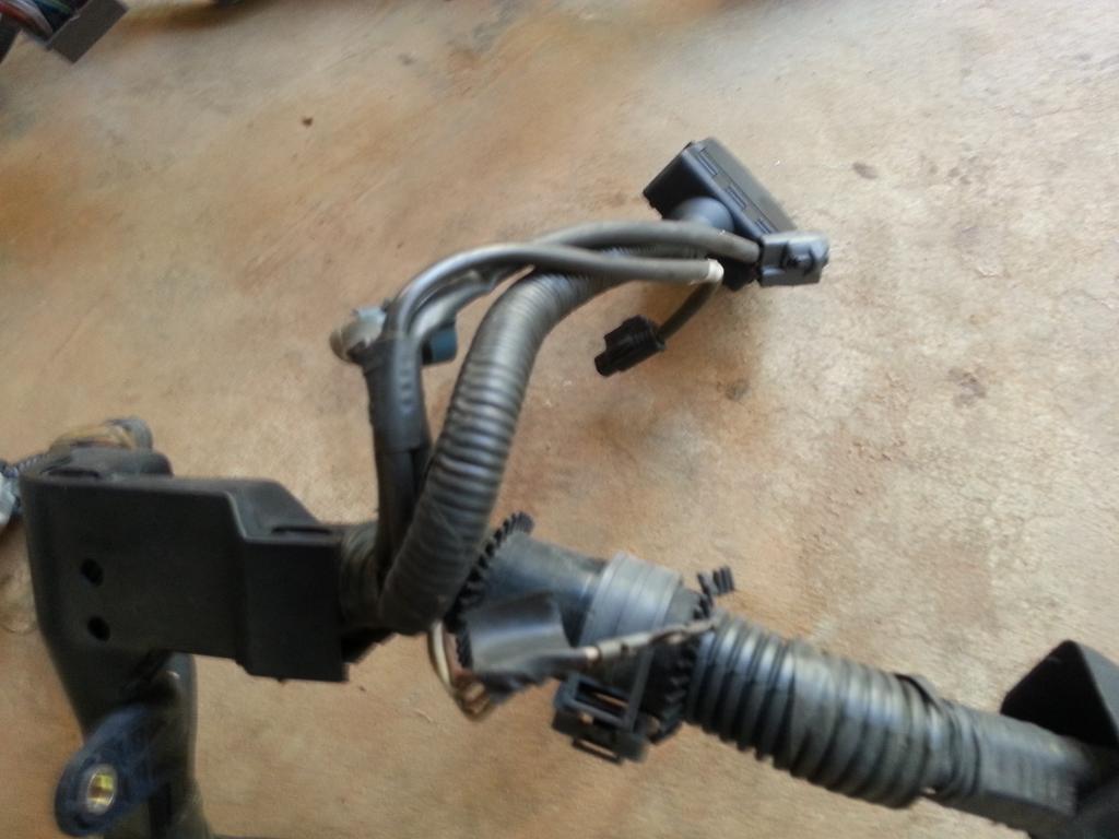
REFERENCE INFO for JDM 2jzgte Engine - ECU PINOUT
80 pin connector on the left and 40 pin connector on the right.
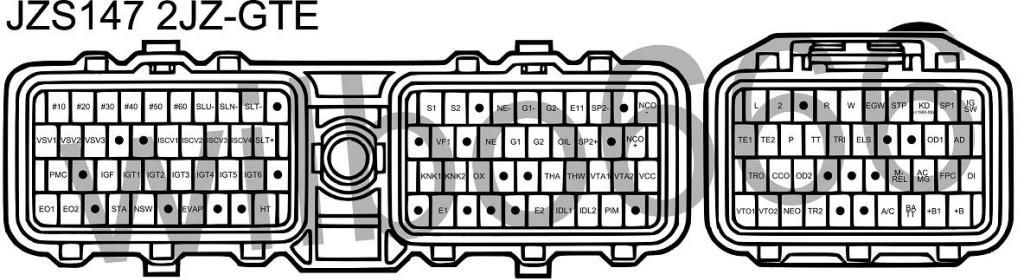
40 Pins Plug - Configuration ( Pin Number , Symbol , Definition , Input or Output , Description )
Pin 1 - IGSW , Ignition Switch , Input , This pin is used to determine if the ignition is ON. The engine ECU is turned on by this signal. This pin is connected to battery voltage when the ignition switch is in RUN and CRANK positions.
Pin 2 - SP1 , No.1 Speed Sensor , Input , This pin is used to determine vehicle speed.Vehicle speed is used in idle control, automatic transmission shift control, speed limiting etc. Two speed sensors are used to provide a backup. This pin is connected to the combination meter speed output which outputs 4 pulses (Open collector square wave pulses) per No.1 speed sensor shaft revolution. The combination meter receives its speed signal from the No.1 speed sensor which is located on the right, rear side of automatic transmission and outputs 4 pulses (0 to Battery Voltage square wave pulses) per sensor shaft revolution.
Pin 3 - KD , Kick Down Switch , Input , This pin is used to detect when the accelerator pedal is fully depressed. Used to 'kick down' or change down a gear of automatic transmission under full throttle. This pin is Grounded by a switch that is located under the accelerator pedal that is pressed at full throttle. The Kick Down switch is open circuit when the switch is not pressed (Accelerator pedal is not fully depressed). Note: 1991-10 to 1993-08 models only, later models do not have this pin wired or a Kick Down switch installed.
Pin 4 - STP , Stop Light Switch , Input , This pin is used to detect when the brake pedal is depressed. Used to disable the automatic transmission lock up torque converter and exit deceleration fuel cut mode etc. This pin is connected to battery voltage when brake pedal is depressed, the ECU pin is open circuit when the brake pedal is not depressed.
Pin 5 - EGW , Exhaust Gas Temperature Warning Light (Catalytic Converter) , Output , This pin is used to turn ON / OFF the exhaust gas warning light. The exhaust gas warning light comes on to inform of an overheated catalytic converter. This pin is Grounded by the ECU as required to turn the exhaust gas warning light ON. Light ON = Error Condition, light OFF = Normal.
Pin 6 - W , Engine Warning Light (Check Engine Light) , Output , This pin is used to turn ON / OFF the check engine light. The check engine light comes on to inform of a detected engine issue. This pin is Grounded by the ECU as required to turn the Check Engine Light ON. The check engine light should be wired with one side of the light connected to battery voltage (Ignition Switched) and one side of the light connected to this ECU pin. Light ON = Error Condition, light OFF = Normal.
Pin 7 - R , Reverse Gear Automatic Transmission Position Indicator , Input , This pin is used to determine if the automatic transmission shifter is in the Reverse position. The engine ECU needs to energize/de-energize the automatic transmission solenoids to select the correct gear. This pin is connected to battery voltage by the automatic shifter position switch when the automatic transmission shifter is in the 'R' position.
Pin 8 - / / / / / /
Pin 9 - 2 , 2nd Gear Automatic Transmission Position Indicator , Input , This pin is used to determine if the automatic transmission shifter is in the 2nd position. The engine ECU needs to energize/de-energize the automatic transmission solenoids to select the correct gear. This pin is connected to battery voltage by the automatic shifter position switch when the automatic transmission shifter is in the '2' position.
Pin 10 - L , Low Gear Automatic Transmission Position Indicator , Input , This pin is used to determine if the automatic transmission shifter is in the L position. The engine ECU needs to energize/de-energize the automatic transmission solenoids to select the correct gear. This pin is connected to battery voltage by the automatic shifter position switch when the automatic transmission shifter is in the 'L' position.
BIG THANKS to the owners of that site for the info and if the link will be deleted because it is not allowed ,just do a google search "WILBO666 2jzgte" .
I am posting the info here so all info that may help you understand your 2jzgte harness better will all be in one place.
REFERENCE INFO for JDM 2jzgte Engine - ECU PINOUT
80 pin connector on the left and 40 pin connector on the right.

40 Pins Plug - Configuration ( Pin Number , Symbol , Definition , Input or Output , Description )
Pin 1 - IGSW , Ignition Switch , Input , This pin is used to determine if the ignition is ON. The engine ECU is turned on by this signal. This pin is connected to battery voltage when the ignition switch is in RUN and CRANK positions.
Pin 2 - SP1 , No.1 Speed Sensor , Input , This pin is used to determine vehicle speed.Vehicle speed is used in idle control, automatic transmission shift control, speed limiting etc. Two speed sensors are used to provide a backup. This pin is connected to the combination meter speed output which outputs 4 pulses (Open collector square wave pulses) per No.1 speed sensor shaft revolution. The combination meter receives its speed signal from the No.1 speed sensor which is located on the right, rear side of automatic transmission and outputs 4 pulses (0 to Battery Voltage square wave pulses) per sensor shaft revolution.
Pin 3 - KD , Kick Down Switch , Input , This pin is used to detect when the accelerator pedal is fully depressed. Used to 'kick down' or change down a gear of automatic transmission under full throttle. This pin is Grounded by a switch that is located under the accelerator pedal that is pressed at full throttle. The Kick Down switch is open circuit when the switch is not pressed (Accelerator pedal is not fully depressed). Note: 1991-10 to 1993-08 models only, later models do not have this pin wired or a Kick Down switch installed.
Pin 4 - STP , Stop Light Switch , Input , This pin is used to detect when the brake pedal is depressed. Used to disable the automatic transmission lock up torque converter and exit deceleration fuel cut mode etc. This pin is connected to battery voltage when brake pedal is depressed, the ECU pin is open circuit when the brake pedal is not depressed.
Pin 5 - EGW , Exhaust Gas Temperature Warning Light (Catalytic Converter) , Output , This pin is used to turn ON / OFF the exhaust gas warning light. The exhaust gas warning light comes on to inform of an overheated catalytic converter. This pin is Grounded by the ECU as required to turn the exhaust gas warning light ON. Light ON = Error Condition, light OFF = Normal.
Pin 6 - W , Engine Warning Light (Check Engine Light) , Output , This pin is used to turn ON / OFF the check engine light. The check engine light comes on to inform of a detected engine issue. This pin is Grounded by the ECU as required to turn the Check Engine Light ON. The check engine light should be wired with one side of the light connected to battery voltage (Ignition Switched) and one side of the light connected to this ECU pin. Light ON = Error Condition, light OFF = Normal.
Pin 7 - R , Reverse Gear Automatic Transmission Position Indicator , Input , This pin is used to determine if the automatic transmission shifter is in the Reverse position. The engine ECU needs to energize/de-energize the automatic transmission solenoids to select the correct gear. This pin is connected to battery voltage by the automatic shifter position switch when the automatic transmission shifter is in the 'R' position.
Pin 8 - / / / / / /
Pin 9 - 2 , 2nd Gear Automatic Transmission Position Indicator , Input , This pin is used to determine if the automatic transmission shifter is in the 2nd position. The engine ECU needs to energize/de-energize the automatic transmission solenoids to select the correct gear. This pin is connected to battery voltage by the automatic shifter position switch when the automatic transmission shifter is in the '2' position.
Pin 10 - L , Low Gear Automatic Transmission Position Indicator , Input , This pin is used to determine if the automatic transmission shifter is in the L position. The engine ECU needs to energize/de-energize the automatic transmission solenoids to select the correct gear. This pin is connected to battery voltage by the automatic shifter position switch when the automatic transmission shifter is in the 'L' position.
Last edited by gerrb; 01-19-14 at 10:28 AM.
01-03-14 | 05:24 PM
#1992
Thread Starter
Super Moderator
iTrader: (34)
Joined: May 2009
Posts: 6,135
Likes: 432
From: A Mile Ahead of You
REFERENCE INFO for JDM 2jzgte Engine - ECU PINOUT
Pin 10 - L , Low Gear Automatic Transmission Position Indicator , Input , This pin is used to determine if the automatic transmission shifter is in the L position. The engine ECU needs to energize/de-energize the automatic transmission solenoids to select the correct gear. This pin is connected to battery voltage by the automatic shifter position switch when the automatic transmission shifter is in the 'L' position.
Pin 11 - AD , Auto Drive , Input , This pin is used to signal that cruise control is ON to the engine ECU. Currently unsure what exact action the engine ECU takes based on this signal. This pin is Grounded by the Cruise Control ECU when Auto Drive is engaged.
Pin 12 - OD1 , Over Drive Disable 1 , Input , This pin is used by the Cruise Control ECU to request to disable the automatic transmission over drive gear (4th Gear). The cruise control ECU may need to change to 3rd gear from 4th gear (over drive) to maintain the desired set speed. This pin is Grounded by the Cruise Control ECU to disable the automatic transmissions over drive gear.
Pin 13 / / / / / /
Pin 14 / / / / / /
Pin 15 - ELS , Electrical Load Sense , Input , This pin is used to signal that heavy electrical loads are ON (e.g. rear demister). Heavy electrical loads place more load on the alternator and hence the engine, the engine ECU can adjust for these heavy electrical loads if it is aware of them. This pin is connected to battery voltage when a heavy electrical load is ON.
Pin 16 - TRI , Timing Retard 1? , Input , Timing Retard perhaps? , Reduced ignition time will reduce engine power which is used by the Traction Control ECU to attempt to maintain traction. This pin connects to the Traction Control ECU pin MPC. Perhaps this should be labelled TR1 and have a similar function to TR2?
Pin 17 - TT , Test Terminal , Output , This pin is used to output a diagnostic voltage dependent on throttle position, brake pedal position and automatic transmission gear position. Used to help in diagnosing issues with the TPS, brake and automatic transmission. Refer to TT section.
Pin 18 - P , Power / Normal Auto , Input , This pin is used to select Power or Normal shift patterns for the automatic transmission. Used to modify the automatic transmission shift points to make the automatic transmission shifts more performance orientated. This pin is connected to battery voltage when the Power / Normal switch is in the Power position. Pin is open circuit when the Power / Normal switch is in the Normal Position. In power mode gears are held longer and the automatic transmission will not select 1st gear when the automatic shifter is manually placed in the '2' position.
Pin 19 - TE2 , Test mode select 2 , Input , This pin is used to select the test mode during which diagnostic serial data is sent out the VF1 pin. Used to help in diagnosing issues. This pin is connected to Ground to enable test mode.
Pin 20 - TE1 , Test mode select 1 , Input , This pin is used to select the test mode during which diagnostic codes are flashed on the check engine light . Used to help in diagnosing issues. This pin is connected to Ground to enable test mode.
Pin 21 - DI , Diagnostic Indication - Fuel Pump Control , Input , This pin is used to determine if the Fuel Pump ECU is healthy. Lets the engine ECU know if the Fuel Pump ECU is healthy, if the Fuel Pump ECU is not healthy the engine ECU stops the output on the FPC pin. This pin is connected to battery voltage when the Fuel Pump ECU is healthy, the pin is open circuit when Fuel Pump ECU is not healthy.
Pin 22 - FPC , Fuel Pump Control , Output , This pin is used to signal the desired fuel pump speed to the Fuel Pump ECU. The fuel pump speed can be reduced at low load conditions to make the fuel quieter and improve fuel pump longevity. This pin outputs a 0V to 5V Pulse Width Modulated (PWM) signal which is connected to the Fuel Pump ECU to control fuel pump speed.
Pin 23 - ACMG , Air Conditioning (AC) Magnetic Clutch Relay , Output , This pin is used to turn the AC magnetic clutch relay ON. ECU control of the AC enables the AC to be turned off during hard acceleration. This pin is Grounded by the ECU as required to turn the AC magnetic clutch relay ON. One side of the AC magnetic clutch relay coil should be wired to this pin and one side of the AC magnetic clutch relay coil should be connected to battery voltage (Ignition switched) and one side of the relay coil connected to this ECU pin.
Pin 24 , M-REL , EFI Main Relay , Output , This pin is used to turn ON the Main EFI Relay which feeds power to the fuel pump, engine ECU, ISCV, engine VSVs and O2 sensor heater circuits, etc. ECU control of the main power relay allows the ECU to remain powered up after engine shutdown to fully open the ISCV. This pin is connected to battery voltage inside the ECU as required to turn the Main EFI Relay ON when the ignition switch is ON. Note that this pin continues to output voltage for a few second after the ignition has been switched off to allow the ISCV to be fully opened by the ECU for the next engine start. One side of the Main EFI Relay coil should be connected to this pin and one side of the Main EFI Relay coil should be connected to Ground.
Pin 25 / / / / / /
Pin 26 / / / / / /
Pin 27 / / / / / /
Pin 28 - OD2 , Over Drive Disable 2 , Input , This pin is used to disable the automatic transmission over drive gear (4th Gear) by a user switch. Used to enable the driver to disable the automatic transmission over drive gear (4th Gear) for towing, hills, etc. This pin is Grounded by the over drive switch to disable the automatic transmission over drive gear.
Pin 29 - CCO , Catalytic Converter Temperature Sensor , Input , This pin is used to measure the catalytic converter temperature. Used to inform the driver of an overheated catalytic converter. This pin connects to a thermistor that is installed after the catalytic converter to sense the catalytic converter temperature. One side of the thermistor should be wired to this pin and one side of the thermistor should be wired to Ground.
Pin 30 - TRO , Timing Retard 0? , Input Timing Retard perhaps? , Reduced ignition time will reduce engine power which is used by the Traction Control ECU to attempt to maintain traction. This pin connects to the Traction Control ECU pin MPR. Perhaps this should be labelled TR0 and have a similar function to TR2?
Pin 31 - +B , EFI Main Relay Switched Power , Input , This pin is used to supply switched battery power to the ECU. Used to supply power. This pin is connected to battery voltage when the Main EFI Relay is energized to supply power to the ECU. The Main EFI Relay is triggered by the engine ECU pin M-REL pin. This pin is connected inside the ECU to the +B1 pin.
Pin 32 - +B1 , EFI Main Relay Switched Power , Input , This pin is used to supply switched battery power to the ECU. Used to supply power. This pin is connected to battery voltage when the Main EFI Relay is energized to supply power to the ECU. The Main EFI Relay is triggered by the engine ECU M-REL pin. This pin is connected inside the ECU to the +B pin.
Pin 33 - BATT , Battery Power , Input , This pin is used to supply constant battery power to the ECU. Constant battery power allows the engine ECU to retain error codes, fuel trims, etc. This pin is connected to battery voltage at all times.
Pin 34 - A/C , Air Conditioning (AC) Request Signal , Input , This pin is used to request that the AC be turned ON. Having an AC request input and a separate control output allows the engine ECU to turn the AC OFF under some conditions, such as hard acceleration. This pin is connected to battery voltage to request that the AC be turned ON. The AC request signal is usually generated by the climate control ECU, however connecting this pin to battery voltage will not guarantee that the AC is turned ON.
Pin 35 / / / / / /
Pin 36 / / / / / /
Pin 37 - TR2 , Timing Retard 2 , Input , This pin is used as a signal to request that the engine ECU retard engine ignition timing. Reduced ignition time will reduce engine power which is used by the Traction Control ECU to attempt to maintain traction. This pin connects to the Traction Control ECU pin TR2.
Pin 38 - NEO , Slave Engine Speed Sensor , Output , This pin is used to supply a copy of the engine speed (NE) signal to the traction control ECU. Engine speed is a useful parameter for traction control. This pin connects to the Traction Control ECU pin NEO.
Pin 39 - VTO2 , Slave Traction Control Throttle Position Sensor , Output , This pin is used to supply a copy of the analogue traction control throttle position (VTA2) signal to the traction control ECU. The measured position of the traction control throttle is a useful parameter for traction control. This pin connects to the Traction Control ECU pin VSH.
Pin 40 - VTO1 , Slave Throttle Position Sensor , Output , This pin is used to supply a copy of the analogue throttle position signal (VTA1) to the traction control ECU. The measured position of the engine throttle is a useful parameter for traction control. This pin connects to the Traction Control ECU pin VTH.
Last edited by gerrb; 01-19-14 at 10:29 AM.
01-03-14 | 06:05 PM
#1993
Thread Starter
Super Moderator
iTrader: (34)
Joined: May 2009
Posts: 6,135
Likes: 432
From: A Mile Ahead of You
Somebody just asked me a question whether this 2jzgte harness build be the same as that of a 240sx with 2jzgte swap. Another one asked if I can work on their car's engine install .
A 2jzgte swap is a 2jzgte swap regardless of what car you are installing your 2jzgte engine. They will only all differ on the body plugs . Those body plugs are distinct for each car . As long as you get the diagrams for the particular car where those wires on those body plugs go to , it will be easy. That is the reason , I will try my best to post information of every pin of those connectors so whatever car you install your 2jzgte engine , you know what the wire is for.
I don't work on other people's cars. I help my local friends , that's about it. A lot of local people already have requested me to work on their cars but I always said the same thing. Sorry , that is not something I would like to do. Though I will be willing to answer any question anyone may have . First I am not a mechanic , I am just a DIY dude just like many here that is just a few pages ahead in reading information that is available on the net . My bachelors and master's degree has nothing to do with working on cars , lmaol , so do not let me work on your car and experiment on it
  .
.
A 2jzgte swap is a 2jzgte swap regardless of what car you are installing your 2jzgte engine. They will only all differ on the body plugs . Those body plugs are distinct for each car . As long as you get the diagrams for the particular car where those wires on those body plugs go to , it will be easy. That is the reason , I will try my best to post information of every pin of those connectors so whatever car you install your 2jzgte engine , you know what the wire is for.
I don't work on other people's cars. I help my local friends , that's about it. A lot of local people already have requested me to work on their cars but I always said the same thing. Sorry , that is not something I would like to do. Though I will be willing to answer any question anyone may have . First I am not a mechanic , I am just a DIY dude just like many here that is just a few pages ahead in reading information that is available on the net
. My bachelors and master's degree has nothing to do with working on cars , lmaol , so do not let me work on your car and experiment on it .
Last edited by gerrb; 01-19-14 at 10:31 AM.