2jzGTE SCs - The Siblings of my Supra MKIV Toys
 01-07-14, 06:55 AM
#2026

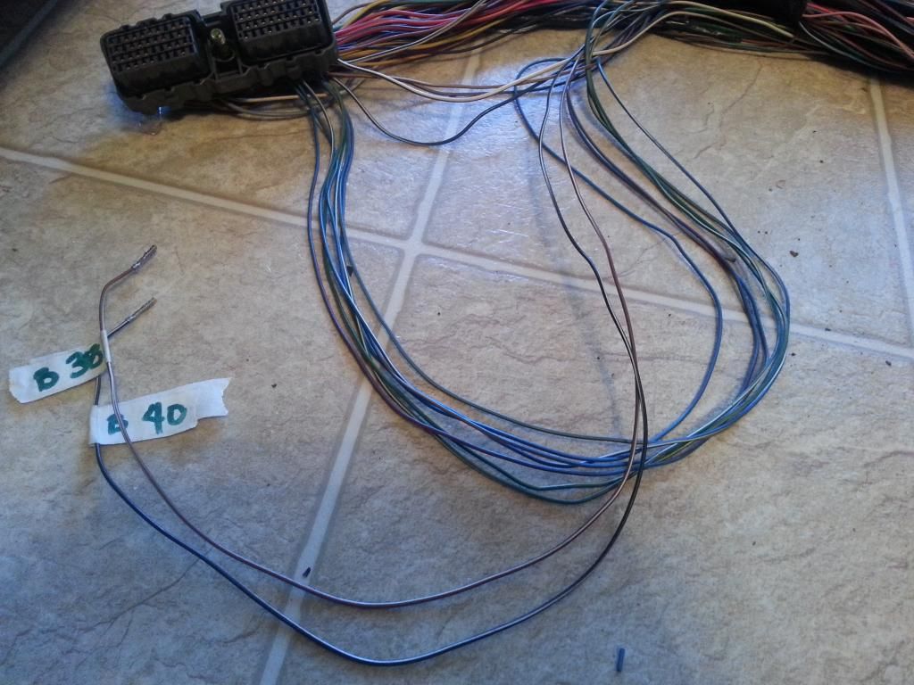
Pictures of the Ignition coils connectors .. from right to left you have Ignition Coil #1 , #2 , #3 , #4 , #5 , #6 and then the 2 VSV connectors
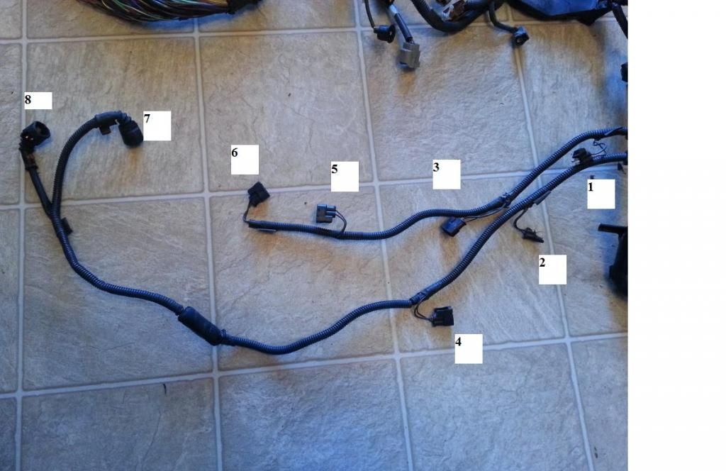
Info you need so you can do THE DRILL .
As pictured above we have
1) Ignition Coil Plug 1
Pin 1 of the Ignition Coil Plug 1 goes to Pin 1 of the Noise Filter & goes to Pin 2 of the 4 pin Igniter Connector & goes to Pin 1 of Ignition Coil 2 , 3, 4, 5, 6 ( & should go to ( SC3 IJ1-7 , SC4 EB2-2 , MK4 IJ1-1 or IJ1-9))
Pin 2 of the Ignition Coil Plug 1 goes to Pin 6 of the 12 Pin Igniter Connector
2) Ignition Coil Plug 2
Pin 1 of the Ignition Coil Plug 2 goes to Pin 1 of the Noise Filter & goes to Pin 2 of the 4 pin Igniter Connector & goes to Pin 1 of Ignition Coil 1, 3, 4, 5, 6 ( & should go to ( SC3 IJ1-7 , SC4 EB2-2 , MK4 IJ1-1 or IJ1-9))
Pin 2 of the Ignition Coil Plug 2 goes to Pin 5 of the 12 Pin Igniter Connector
3) Ignition Coil Plug 3
Pin 1 of the Ignition Coil Plug 3 goes to Pin 1 of the Noise Filter & goes to Pin 2 of the 4 pin Igniter Connector & goes to Pin 1 of Ignition Coil 1 , 2, 4, 5, 6 ( & should go to ( SC3 IJ1-7 , SC4 EB2-2 , MK4 IJ1-1 or IJ1-9))
Pin 2 of the Ignition Coil Plug 3 goes to Pin 4 of the 12 Pin Igniter Connector
4) Ignition Coil Plug 4
Pin 1 of the Ignition Coil Plug 4 goes to Pin 1 of the Noise Filter & goes to Pin 2 of the 4 pin Igniter Connector & goes to Pin 1 of Ignition Coil 1 , 2, 3, 5, 6 ( & should go to ( SC3 IJ1-7 , SC4 EB2-2 , MK4 IJ1-1 or IJ1-9))
Pin 2 of the Ignition Coil Plug 4 goes to Pin 10 of the 12 Pin Igniter Connector
5) Ignition Coil Plug 5
Pin 1 of the Ignition Coil Plug 5 goes to Pin 1 of the Noise Filter & goes to Pin 2 of the 4 pin Igniter Connector & goes to Pin 1 of Ignition Coil 1 , 2, 3, 4, 6 ( & should go to ( SC3 IJ1-7 , SC4 EB2-2 , MK4 IJ1-1 or IJ1-9))
Pin 2 of the Ignition Coil Plug 5 goes to Pin 11 of the 12 Pin Igniter Connector
6) Ignition Coil Plug 6
Pin 1 of the Ignition Coil Plug 6 goes to Pin 1 of the Noise Filter & goes to Pin 2 of the 4 pin Igniter Connector & goes to Pin 1 of Ignition Coil 1 , 2, 3, 4, 5 ( & should go to ( SC3 IJ1-7 , SC4 EB2-2 , MK4 IJ1-1 or IJ1-9))
Pin 2 of the Ignition Coil Plug 6 goes to Pin 12 of the 12 Pin Igniter Connector
7) VSV1 ( Intake Air Control Valve )
Pin 1 of the VSV1 goes to Pin 1 of the VSV3 & goes to Pin 2 of the Oxygen Sensor Connector ( & should go to Pin 12 of the Data Link Connector & to ( SC3 IJ1-12 & EB2-1 & Short-4 , SC4 IJ1-12 & EB2-3 , MK4 EA3-3 ))
Pin 2 of the VSV1 goes to Pin 40 of the 80 pin ECU Connector
8) VSV3( Exhaust Bypass Valve )
Pin 1 of the VSV3 goes to Pin 1 of the VSV1 & goes to Pin 2 of the Oxygen Sensor Connector ( & should go to Pin 12 of the Data Link Connector & to ( SC3 IJ1-12 & EB2-1 & Short-4 , SC4 IJ1-12 & EB2-3 , MK4 EA3-3 ))
Pin 2 of the VSV3 goes to Pin 38 of the 80 pin ECU Connector
Now it is time for you guys to do THE DRILL ( You already know this , right ?)
Last edited by gerrb; 01-24-14 at 12:20 PM.
 01-07-14, 07:34 AM
#2027
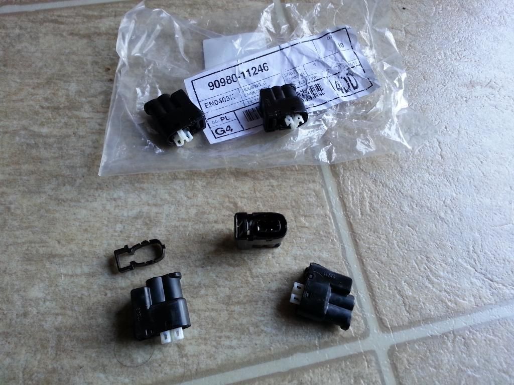
On the harnesses am working on , I have inspected the physical conditions of the plugs.
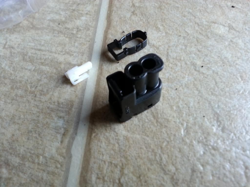
This casing is damaged so it needs to be replaced. Be mindful of where you install the pins where you replace the plug.
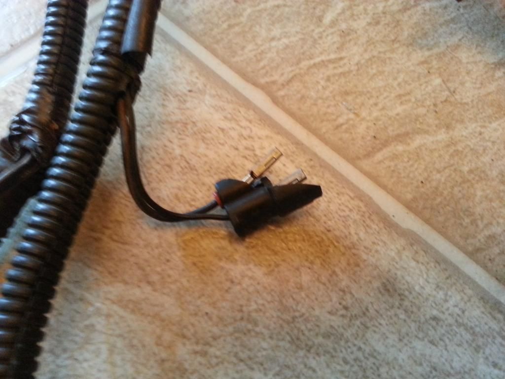
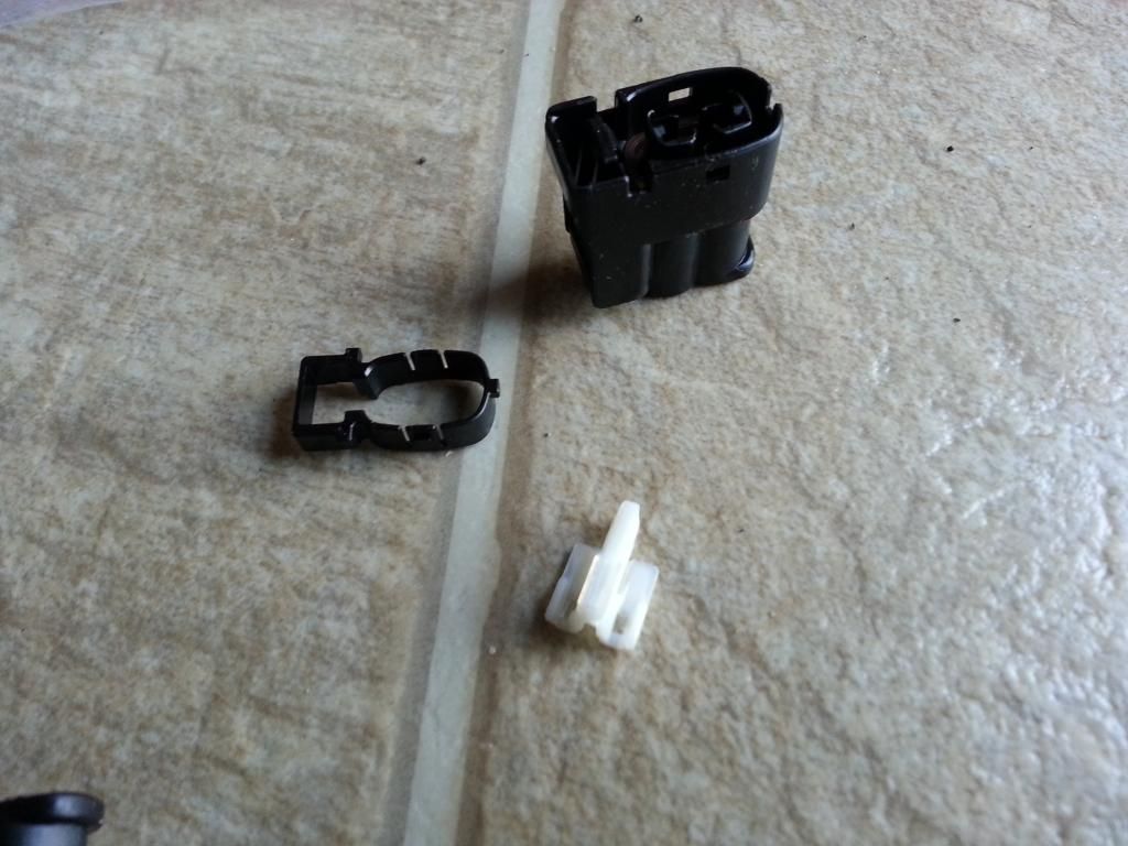
Plastic inserts to hold the two pins inside the plug casing are missing.

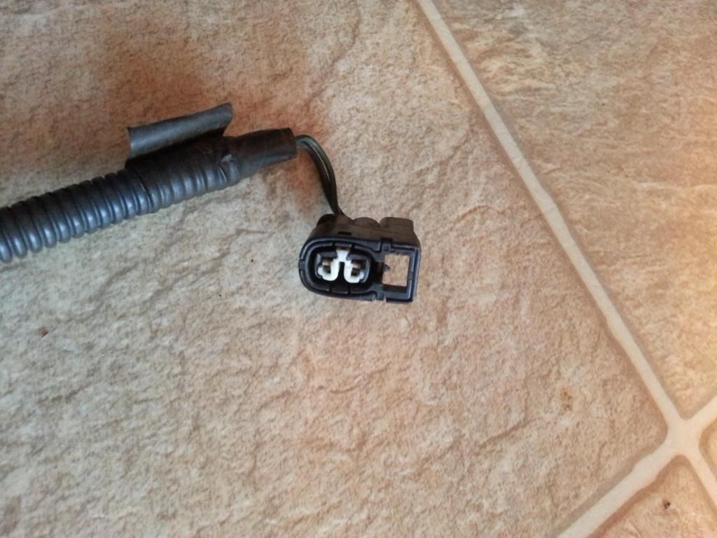
This is how the black and white plastic inserts look like.
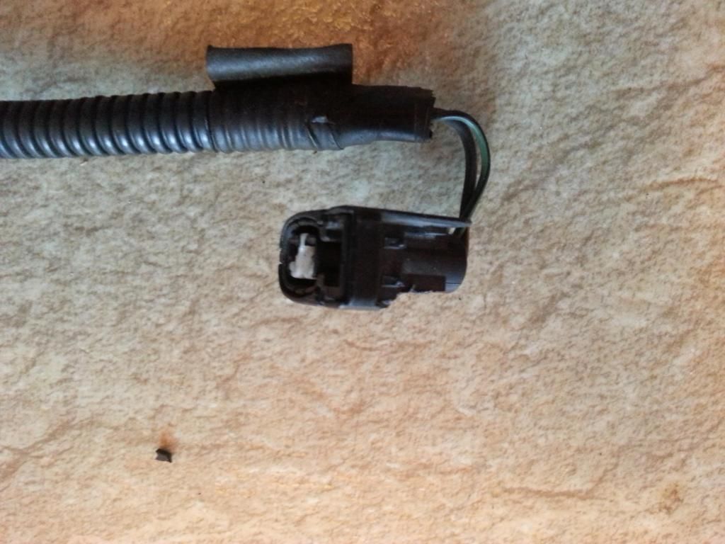
This one has the the plastic inserts but the lock is bad.
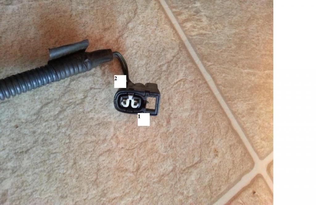
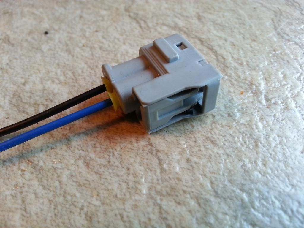
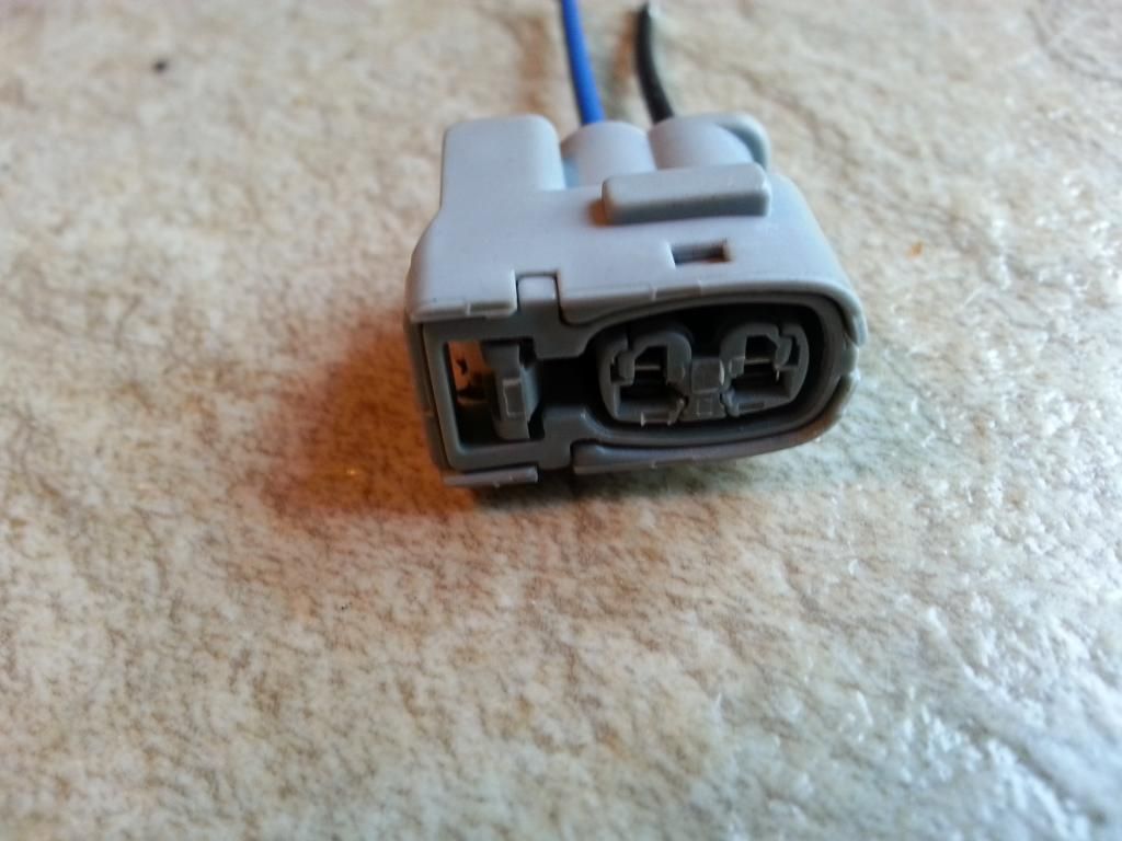
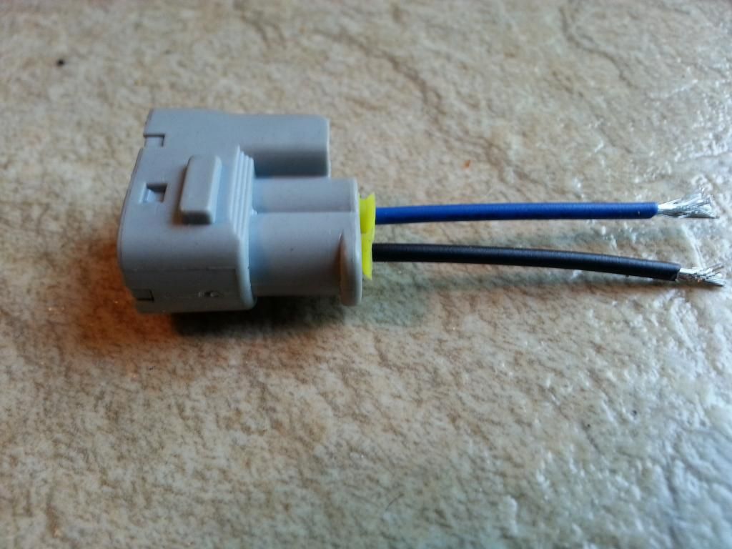
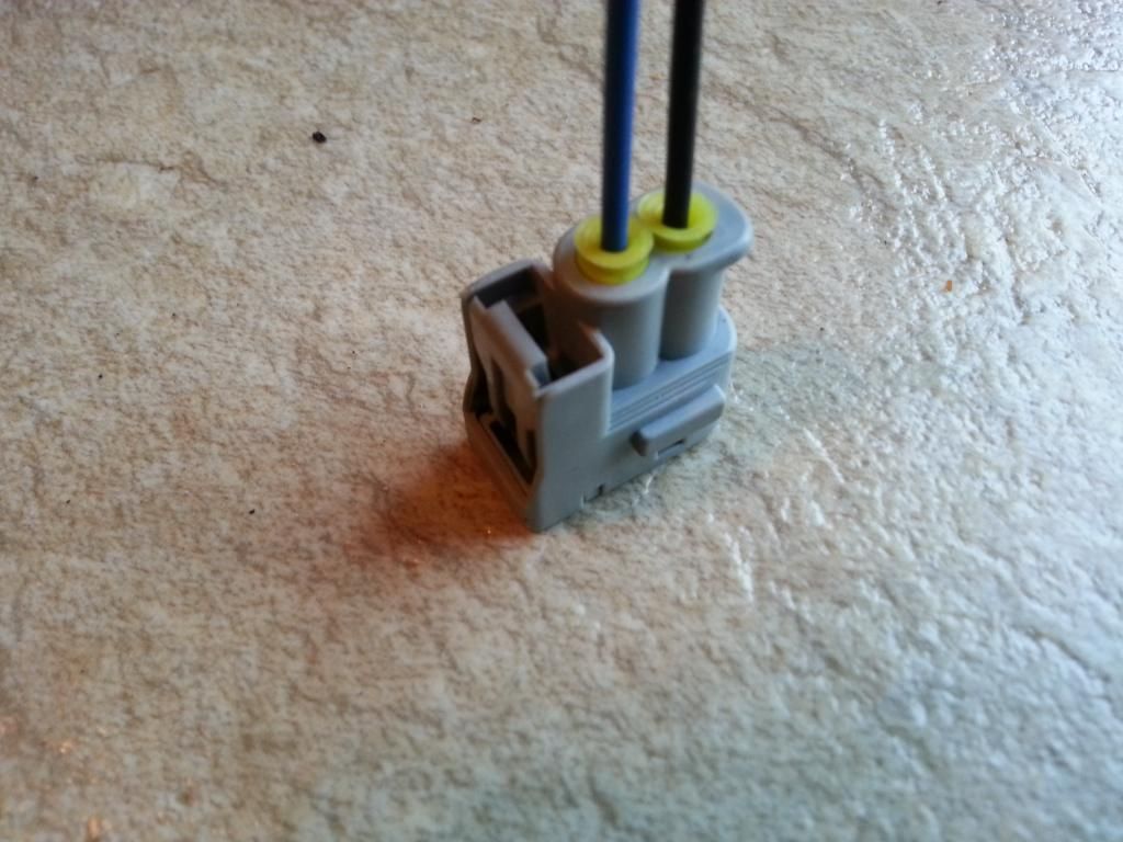
For the Ignition Coil connectors , here are the pin numbering , pin #1 is nearer the lock
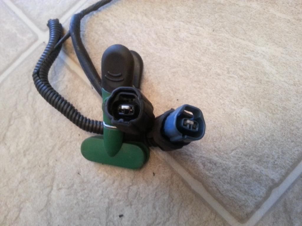
Here is a close up look of the VSV plugs and by now I hope you remember which is pin 1 and pin 2 of every VSV plug (remember ? holding the connector with the lock on top , pin1 is the first on the left ) .
The blue one is VSV1 which is for the Air Intake Control Valve
The black one is VSV3 which is for the Exhaust Bypass Valve
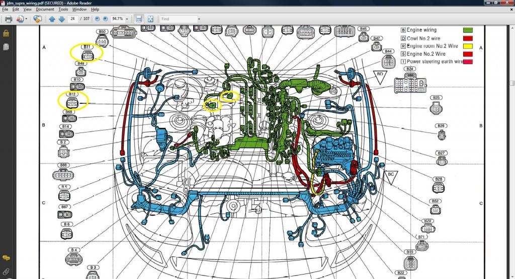
This is a JDM Supra with 2jzgte , you see were the VSVs are laid out
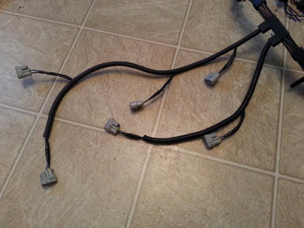
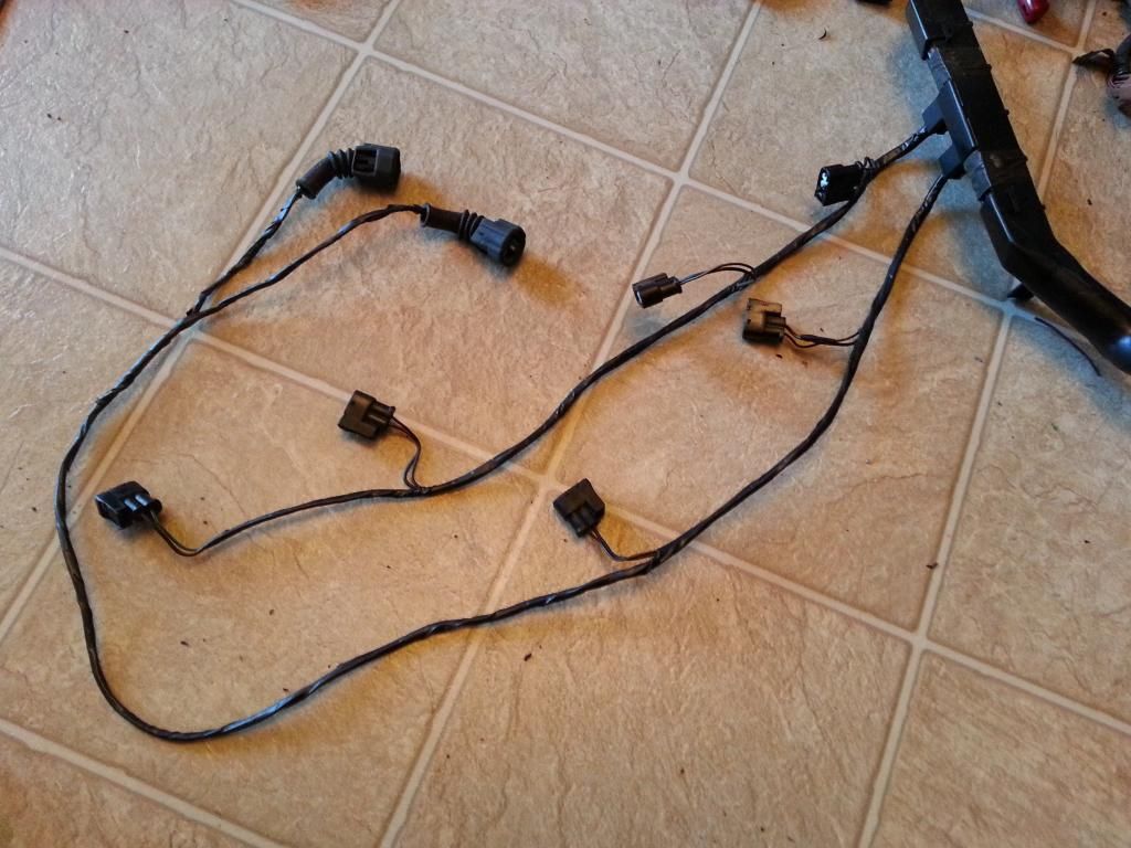
Cleaned up the wrap on that part of the harness where the ignition coil connectors are.
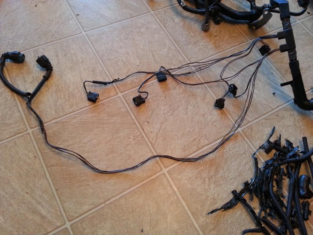
Now that part of the harness is unwrapped , it is easy to remove the plugs and wires we do not need. Like if you are going single turbo or aftermarket twins , the wires and plugs for the VSVs are not needed. If you are going stock twin turbo , do not remove those, just make sure the connectors are good.
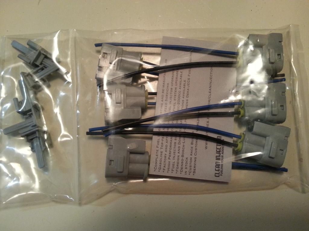
Aaron bought new ignition coil pigtails for his harness. He bought aftermarket plugs and were cheaper than the OEM plugs I bought for mine .

This casing is damaged so it needs to be replaced. Be mindful of where you install the pins where you replace the plug.

Plastic inserts to hold the two pins inside the plug casing are missing.

This is how the black and white plastic inserts look like.

This one has the the plastic inserts but the lock is bad.

For the Ignition Coil connectors , here are the pin numbering , pin #1 is nearer the lock

Here is a close up look of the VSV plugs and by now I hope you remember which is pin 1 and pin 2 of every VSV plug (remember ? holding the connector with the lock on top , pin1 is the first on the left ) .
The blue one is VSV1 which is for the Air Intake Control Valve
The black one is VSV3 which is for the Exhaust Bypass Valve

This is a JDM Supra with 2jzgte , you see were the VSVs are laid out

Cleaned up the wrap on that part of the harness where the ignition coil connectors are.

Now that part of the harness is unwrapped , it is easy to remove the plugs and wires we do not need. Like if you are going single turbo or aftermarket twins , the wires and plugs for the VSVs are not needed. If you are going stock twin turbo , do not remove those, just make sure the connectors are good.
Aaron bought new ignition coil pigtails for his harness. He bought aftermarket plugs and were cheaper than the OEM plugs I bought for mine .


Last edited by gerrb; 01-24-14 at 12:21 PM.
01-07-14, 07:47 AM
#2028
Q) Apparently all those connectors you need to replace are added to the cost of the harness if you do it yourself . Wouldn't it be better to have them before hand ?
Thanks for pointing that thing out . You are perfectly right , before working on the harness , do a thorough inspection of it. Check all broken connectors and order them so you have them when you need them . . Again thank you
  . My bad for not mentioning that .
With regards the cost of the connectors , whether you or someone else will do your harness , they will charge you anyway for those connectors , either way you pay for them. NOT UNLESS you are buying a brand new 2jzgte wiring harness. Usually you are buying a stock harness with basic components . IF you need extra wiring for extra components incorporated , it will be more costs. And as I previously mentioned an auto transmission 2jzgte harness usually costs more than a manual transmission 2jzgte harness. A brand new 2jzgte harness for manual transmission will be in the vicinity of $1000 and for auto transmission will be in the vicinity of $1200 . So for whatever you want to be added particular to your setup , it's an added cost.
Thanks for pointing that thing out . You are perfectly right , before working on the harness , do a thorough inspection of it. Check all broken connectors and order them so you have them when you need them .
. Again thank you . My bad for not mentioning that .With regards the cost of the connectors , whether you or someone else will do your harness , they will charge you anyway for those connectors , either way you pay for them. NOT UNLESS you are buying a brand new 2jzgte wiring harness. Usually you are buying a stock harness with basic components . IF you need extra wiring for extra components incorporated , it will be more costs. And as I previously mentioned an auto transmission 2jzgte harness usually costs more than a manual transmission 2jzgte harness. A brand new 2jzgte harness for manual transmission will be in the vicinity of $1000 and for auto transmission will be in the vicinity of $1200 . So for whatever you want to be added particular to your setup , it's an added cost.
Last edited by gerrb; 01-07-14 at 08:01 AM.
01-07-14, 08:48 AM
#2029
The aftermarket plugs were nice. My only gripe was some wires were not properly crimped inside the plug .
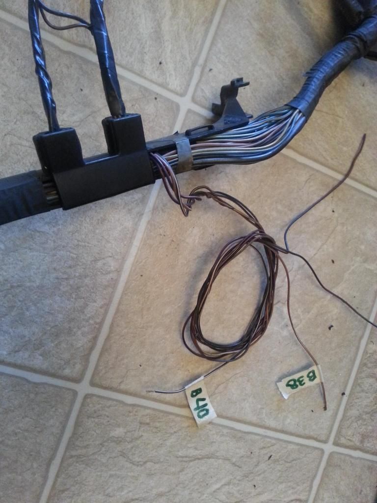
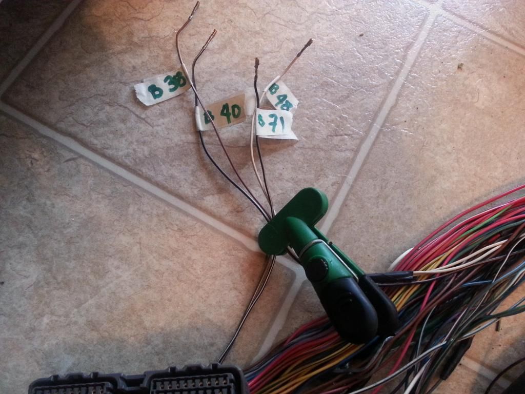
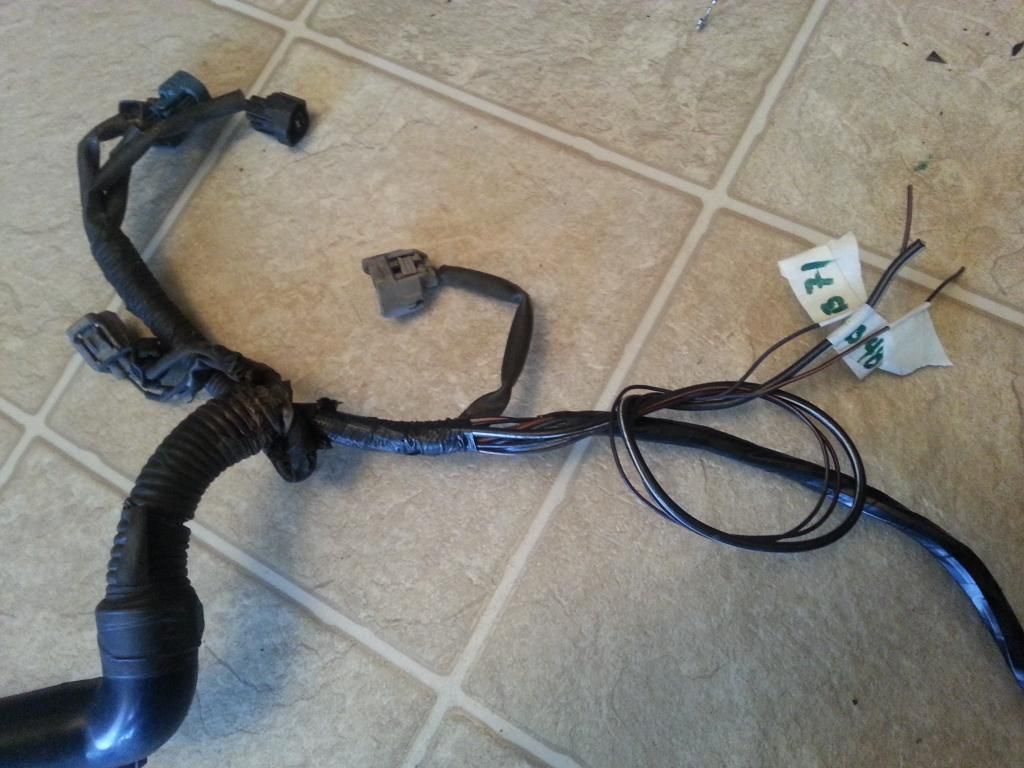
Aaron's harness with ignition coil plugs replaced and the two VSV plugs & wires pulled out from that area .
Since he didn't need the 2 VSV plugs , pulled them out from that area and labeled the two wires that go direct to the 80 pin ECU connector
Extended the wires .

Pulled those wires nearer the ECU Connectors
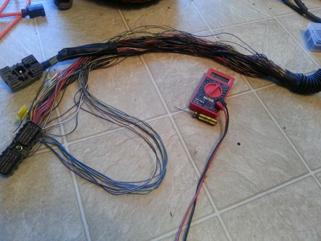
Took the pins out of the 80 pin ECU connector and labeled them
For Aaron's harness , you see that I used also the oxygen sensor wires as extra wires so I had to label them accordingly too.
Stock / OEM coil plug housing for my Red Mamba 1
Ignition Coil Plugs and VSV3 plug for my Red Mamba 2 had been replaced . As you probably noticed I am not wrapping mine with corrugated flexible hose yet . It is because I have none as of this writing .
.
For Aaron's and my Red Mamba 1 harness, we re-used the wires of the oxygen sensor for our Boost Solenoid since one is a B+ supply and one goes directly to pin 71 . Temporarily so they are out of the way , rolled them but labeled them though so it is easy for me to know which is which later.
Before I forget , let me add something here ...
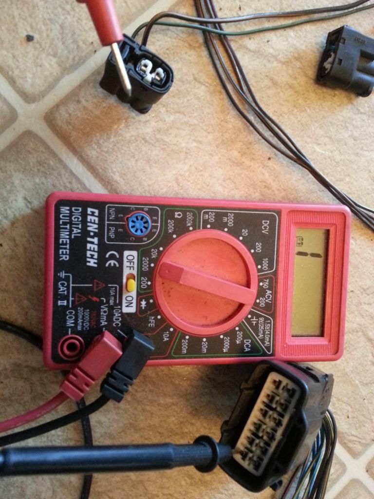
Pin 48 of the ECU 80 pin connector is for the signal of the Oxygen Sensor , it gives a feedback to the ECU on how much is the air fuel ratio measured at the exhaust so the ECU can actually adjust fuel trim for the injectors. This wire is SHIELDED . Observe it , it is thicker because of the shield around the middle / signal wire . Most signal wires which are very important to the ECU are shielded just like the cam and crank sensors signal wires so to prevent any interference. We will leave it like that . I won't explain what interference and from where so as not to confuse non electrical people. That won't stop you from going ahead anyway. It would suffice to know that you will have to extend the wire after the shield , nearer the connector itself. Also you will find another wire almost same wire with shield connected to that wire , it goes to a pin in the diagnostic port which we will tackle later.
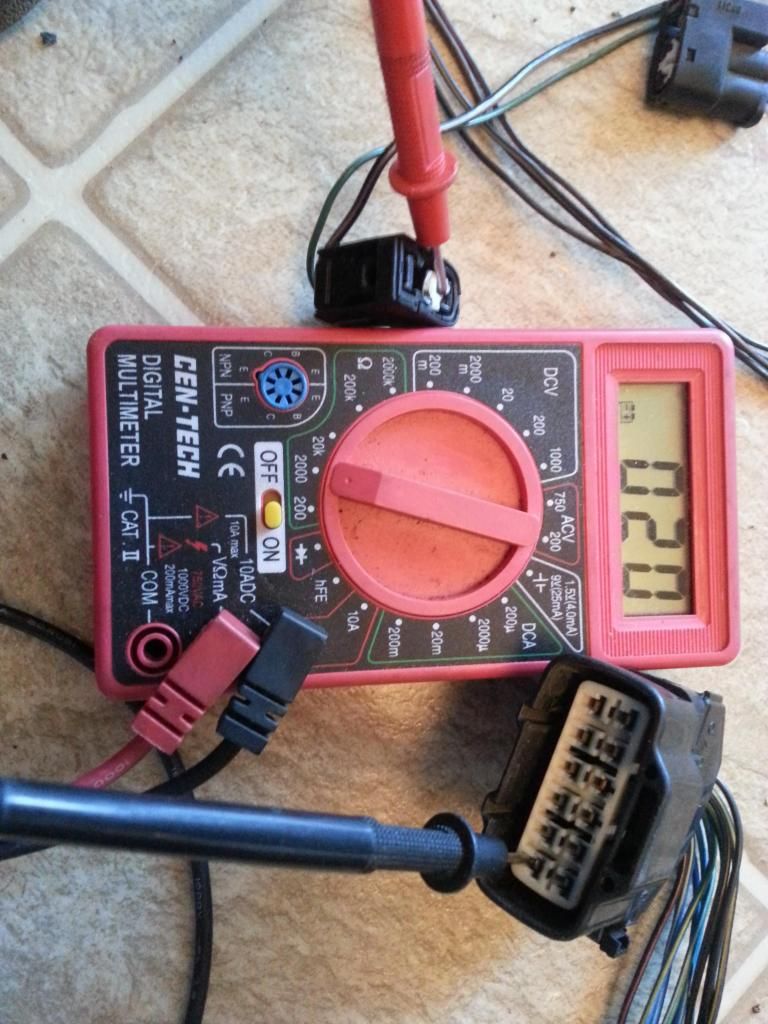
Did probe for connectivities for all the wires like PIn 2 of Ignition Coil 6 and Pin 12 of the 12 Pin Igniter Connector .
Aaron's harness with ignition coil plugs replaced and the two VSV plugs & wires pulled out from that area .

Since he didn't need the 2 VSV plugs , pulled them out from that area and labeled the two wires that go direct to the 80 pin ECU connector

Extended the wires .

Pulled those wires nearer the ECU Connectors

Took the pins out of the 80 pin ECU connector and labeled them

For Aaron's harness , you see that I used also the oxygen sensor wires as extra wires so I had to label them accordingly too.

Stock / OEM coil plug housing for my Red Mamba 1


Ignition Coil Plugs and VSV3 plug for my Red Mamba 2 had been replaced . As you probably noticed I am not wrapping mine with corrugated flexible hose yet . It is because I have none as of this writing
.
For Aaron's and my Red Mamba 1 harness, we re-used the wires of the oxygen sensor for our Boost Solenoid since one is a B+ supply and one goes directly to pin 71 . Temporarily so they are out of the way , rolled them but labeled them though so it is easy for me to know which is which later.

Before I forget , let me add something here ...
Pin 48 of the ECU 80 pin connector is for the signal of the Oxygen Sensor , it gives a feedback to the ECU on how much is the air fuel ratio measured at the exhaust so the ECU can actually adjust fuel trim for the injectors. This wire is SHIELDED . Observe it , it is thicker because of the shield around the middle / signal wire . Most signal wires which are very important to the ECU are shielded just like the cam and crank sensors signal wires so to prevent any interference. We will leave it like that . I won't explain what interference and from where so as not to confuse non electrical people. That won't stop you from going ahead anyway. It would suffice to know that you will have to extend the wire after the shield , nearer the connector itself. Also you will find another wire almost same wire with shield connected to that wire , it goes to a pin in the diagnostic port which we will tackle later.
Did probe for connectivities for all the wires like PIn 2 of Ignition Coil 6 and Pin 12 of the 12 Pin Igniter Connector .


Last edited by gerrb; 01-24-14 at 10:45 AM.
01-07-14, 09:14 AM
#2030
Q) Since we know that our base harness is a 2jzgte Aristo harness and was working with the engine swap we bought , why don't we just replace all those broken plugs , be done with the 2jzgte part of the harness and all we have to work on are connecting the body plugs ?
That is a pretty good question. That will save us a lot of work if we don't have to do what we are doing right now.
Here is my point of view. IF you just change all the broken plugs , without checking every pin of each connector then you are making an assumption that every wire and unbroken plug that you got was good. What we are doing is not only cleaning up the wiring , replacing broken plugs and extending what needs to be extended , WE ARE ALSO already checking the actual harness itself from every point . It will be very hard to trace and work on broken wires / connectors once that harness is on the engine bay and installed. Much more, if you are building a harness for someone ... you don't want to get a call and let you know that something is wrong.
Last edited by gerrb; 01-07-14 at 09:22 AM.
01-07-14, 10:18 AM
#2031
You have done THE DRILL on the set of plugs we are working on so it is time to update your Chart .
I know that chart is a lot of work . If you are very familiar where a pin should go , you don't need it. But if you are new and want a quick guide later on then do it.. It lets you see at a glance what you have worked on and checked / verified . It will be more valuable for those who cannot read wiring diagrams.
80 PIN ECU CONNECTOR
1
2
10
20
30
38 <--> Pin 2 of the VSV3 CHECKED
40 <--> Pin 2 of the VSV1 CHECKED
48 <--> Pin 3 of the O2 Sensor CHECKED
50
51
52 <--> Pin 7 of the 12 pin Igniter Connector CHECKED
53 <--> Pin 8 of the 12 pin igniter Connector CHECKED
54 <--> Pin 9 of the 12 pin igniter Connector CHECKED
55 <--> Pin 3 of the 12 pin igniter Connector CHECKED
56 <--> Pin 2 of the 12 pin Igniter Connector CHECKED
57 <--> Pin 1 of the 12 pin Igniter Connector CHECKED
58 <--> Pin 3 of the 4 pin Igniter Connector CHECKED
59
60
70
71 <--> Pin 1 of the O2 Sensor CHECKED
80
4 PIN IGNITER CONNECTOR
1 <--> Pin 12 of Plug F of Aristo plug <--> ( Pin 19 of the Data Link Connector <--> ( SC3 IK1-8 , SC4 IK1-8 , MK4 ))
2 <--> Pin 6 of Plug F of Aristo plug <--> Pin 1 of the Noise Filter <--> ( SC3 IJ1-7 , SC4 EB2-2 , MK4 IJ1-1 or IJ1-9 )
3 <--> Pin 58 of the 80 pin ECU connector CHECKED
4 <--> Ground Connector on the Front Side of Intake Manifold <--> Pin 2 of the Noise filter Connector CHECKED
12 PIN IGNITER CONNECTOR
1 <--> Pin 57 of the 80 pin ECU connector CHECKED
2 <--> Pin 56 of the 80 pin ECU connector CHECKED
3 <--> Pin 55 of the 80 pin ECU connector CHECKED
4 <--> Pin 2 of the Ignition Coil Connector 3 CHECKED
5 <--> Pin 2 of the Ignition Coil Connector 2 CHECKED
6 <--> Pin 2 of the Ignition Coil Connector 1 CHECKED
7 <--> Pin 52 of the 80 pin ECU connector CHECKED
8 <--> Pin 53 of the 80 pin ECU connector CHECKED
9 <--> Pin 54 of the 80 pin ECU connector CHECKED
10 <--> Pin 2 of the Ignition Coil Connector 4 CHECKED
11 <--> Pin 2 of the Ignition Coil Connector 5 CHECKED
12 <--> Pin 2 of the Ignition Coil Connector 6 CHECKED
IGNITION COIL 1
1 <--> Pin 1 of the Noise Filter <--> Pin 2 of the 4 pin Igniter Connector <--> Pin 1 of Ignition Coil 2,3,4,5,6 <-->( SC3 IJ1-7 , SC4 EB2-2 , MK4 IJ1-1 or IJ1-9 )
2 <--> Pin 6 of the 12 Pin Igniter Connector CHECKED
IGNITION COIL 2
1 <--> Pin 1 of the Noise Filter <--> Pin 2 of the 4 pin Igniter Connector <--> Pin 1 of Ignition Coil 1,3,4,5,6 <-->( SC3 IJ1-7 , SC4 EB2-2 , MK4 IJ1-1 or IJ1-9 )
2 <--> Pin 5 of the 12 Pin Igniter Connector CHECKED
IGNITION COIL 3
1 <--> Pin 1 of the Noise Filter <--> Pin 2 of the 4 pin Igniter Connector <--> Pin 1 of Ignition Coil 1,2,4,5,6 <-->( SC3 IJ1-7 , SC4 EB2-2 , MK4 IJ1-1 or IJ1-9 )
2 <--> Pin 4 of the 12 Pin Igniter Connector CHECKED
IGNITION COIL 4
1 <--> Pin 1 of the Noise Filter <--> Pin 2 of the 4 pin Igniter Connector <--> Pin 1 of Ignition Coil 1,2,3,5,6 <-->( SC3 IJ1-7 , SC4 EB2-2 , MK4 IJ1-1 or IJ1-9 )
2 <--> Pin 10 of the 12 Pin Igniter Connector CHECKED
IGNITION COIL 5
1 <--> Pin 1 of the Noise Filter <--> Pin 2 of the 4 pin Igniter Connector <--> Pin 1 of Ignition Coil 1,2,3,4,6 <-->( SC3 IJ1-7 , SC4 EB2-2 , MK4 IJ1-1 or IJ1-9 )
2 <--> Pin 11 of the 12 Pin Igniter Connector CHECKED
IGNITION COIL 6
1 <--> Pin 1 of the Noise Filter <--> Pin 2 of the 4 pin Igniter Connector <--> Pin 1 of Ignition Coil 1,2,3,4,5 <-->( SC3 IJ1-7 , SC4 EB2-2 , MK4 IJ1-1 or IJ1-9 )
2 <--> Pin 12 of the 12 Pin Igniter Connector CHECKED
NOISE FILTER
1 <--> Pin 2 of the 4 pin Igniter Connector <--> ( SC3 IJ1-7, SC4 EB2-2 , MK4 IJ1-1 or IJ1-9 )
2 <--> Ground Connector on the Front Side of Intake Manifold <--> Pin 4 of the 4 pin Igniter Connector CHECKED
The following plugs are necessary only if you are going stock 2jzgte setup
Oxygen Sensor O2
1 <--> Pin 71 of the 80 pin ECU Connector CHECKED
2 <--> Pin 3 of Plug E of Aristo Plug <-> (Pin 12 of the Data Link Connector <--> ( SC3 IJ1-12 & EB2-1 & Short-4 , SC4 IJ1-12 & EB2-3 , MK4 EA3-3 ))
3 <--> Pin 48 of the 80 pin ECU Connector CHECKED
VSV1 ( Air Intake Control Valve )
1 <--> Pin 2 of the Oxygen Sensor Connector <--> Pin 1 of the VSV3 <-> (Pin 12 of the Data Link Connector <--> ( SC3 IJ1-12 & EB2-1 & Short-4 , SC4 IJ1-12 & EB2-3 , MK4 EA3-3 ))
2 <--> Pin 40 of the 80 pin ECU Connector CHECKED
VSV3( Exhaust Bypass Valve )
1 <--> Pin 2 of the Oxygen Sensor Connector <-->Pin 1 of the VSV1 <-> (Pin 12 of the Data Link Connector <--> ( SC3 IJ1-12 & EB2-1 & Short-4 , SC4 IJ1-12 & EB2-3 , MK4 EA3-3 ))
2 <--> Pin 38 of the 80 pin ECU Connector CHECKED
The following plugs needs to be taken out
BIG GRAY ARISTO PLUG
PLUG E
3 <--> Pin 2 of Oxygen Sensor <--> (Pin 12 of the Data Link Connector <--> ( SC3 IJ1-12 & EB2-1 & Short-4 , SC4 IJ1-12 & EB2-3 , MK4 EA3-3 ))
PLUG F
6 <--> Pin 1 of the Noise Filter <--> ( SC3 IJ1-7 , SC4 EB2-2 , MK4 IJ1-1 or IJ1-9 )
12 <--> ( Pin 19 of the Data Link Connector & to ( SC3 IK1-8 , SC4 IK1-8 , MK4 ))
Last edited by gerrb; 01-30-14 at 07:25 AM.
01-07-14, 11:03 AM
#2032
So before I go ahead , let me ask this to you guys who have been following this 2jzgte harness build thread. Am I being clear in what I am writing and saying ? Give me a feedback please. I don't want to waste my time continuing and it is all gibberish or german to everyone or nobody understands what I am saying. Just be honest , it won't hurt my feelings cause I don't need this write-up. I can live without it. I can just stop it all here if it is useless. .. lol.
01-07-14, 11:21 AM
#2034
Probe on Pin 1 of the Ignition Coil #1 and should have connectivity with Pin 1 of Ignition Coil #2 , #3 , #4 , #5 , #6 and Pin 1 of the Noise Filter
Probe on Pin 1 of the Ignition Coil #2 and should have connectivity with Pin 1 of Ignition Coil #3 #4 , #5 , #6 and Pin 1 of the Noise Filter
Probe on Pin 1 of the Ignition Coil #3 and should have connectivity with Pin 1 of Ignition Coil #4 , , #5 , #6 and Pin 1 of the Noise Filter
Probe on Pin 1 of the Ignition Coil #1 and should have connectivity with Pin 1 of Ignition Coil #5 , #6 and Pin 1 of the Noise Filter
Probe on Pin 1 of the Ignition Coil #1 and should have connectivity with Pin 1 of Ignition Coil #6 , and Pin 1 of the Noise Filter
Are these correct that are highlighted in red....
 01-07-14, 12:42 PM
#2036
Probe on Pin 1 of the Ignition Coil #1 and should have connectivity with Pin 1 of Ignition Coil #2 , #3 , #4 , #5 , #6 and Pin 1 of the Noise Filter
Probe on Pin 1 of the Ignition Coil #2 and should have connectivity with Pin 1 of Ignition Coil #3 #4 , #5 , #6 and Pin 1 of the Noise Filter
Probe on Pin 1 of the Ignition Coil #3 and should have connectivity with Pin 1 of Ignition Coil #4 , , #5 , #6 and Pin 1 of the Noise Filter
Probe on Pin 1 of the Ignition Coil #1 and should have connectivity with Pin 1 of Ignition Coil #5 , #6 and Pin 1 of the Noise Filter
Probe on Pin 1 of the Ignition Coil #1 and should have connectivity with Pin 1 of Ignition Coil #6 , and Pin 1 of the Noise Filter
Are these correct that are highlighted in red....
Probe on Pin 1 of the Ignition Coil #2 and should have connectivity with Pin 1 of Ignition Coil #3 #4 , #5 , #6 and Pin 1 of the Noise Filter
Probe on Pin 1 of the Ignition Coil #3 and should have connectivity with Pin 1 of Ignition Coil #4 , , #5 , #6 and Pin 1 of the Noise Filter
Probe on Pin 1 of the Ignition Coil #1 and should have connectivity with Pin 1 of Ignition Coil #5 , #6 and Pin 1 of the Noise Filter
Probe on Pin 1 of the Ignition Coil #1 and should have connectivity with Pin 1 of Ignition Coil #6 , and Pin 1 of the Noise Filter
Are these correct that are highlighted in red....
Thanks for the correction . I have edited them . I usually do a cut and paste so as not to retype the whole line and at times I forget to change info that I need to change.
Thank you for catching that !
 thanks .. just wondering , this thread had more than 3000 views in the past 3 days since I started the harness build . I have quite a number of questions though ....I want to make sure that things are making sense . lmaol.
Last edited by gerrb; 01-07-14 at 01:33 PM.
01-07-14, 02:00 PM
#2038
will do for those VSVs you were requesting. Those plugs itself do not need extending . It is the wires that goes from those VSV plugs to the ECU 80 pin connector that needs extending. So if you started extending those Igniter wires with 18" extensions , then you will do the same. Will document them.
01-07-14, 02:02 PM
#2039

wow, that is alot of info in there just seeing it for the first time. Great detail and its nice to see someone else using a multimeter to check the connections and also realize the importance of not having broken connectors, they tend to loose connection at the most inconvenient of times.
Should definitely be helpful to many members, usually people don't share alot on the harness. If you don't mind I might link some of it like removing the ecu pins and ignitor wiring. good luck on the rest of the harness and if you get stuck post it up but looks like you have it down pretty well already!
Should definitely be helpful to many members, usually people don't share alot on the harness. If you don't mind I might link some of it like removing the ecu pins and ignitor wiring. good luck on the rest of the harness and if you get stuck post it up but looks like you have it down pretty well already!
01-07-14, 02:16 PM
#2040
DIAGRAMS TO VERIFY PIN NUMBERING & WHERE THE WIRE GOES
*** Ignition Coils ***
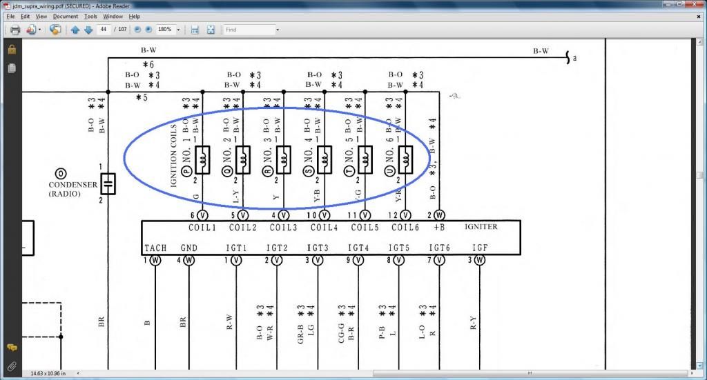
In the diagram above we don't see the Pin 1 of all the Coil Plugs being connected to ( SC3 IJ1-7 , SC4 EB2-2 , MK4 IJ1-1 or IJ1-9) but we see them to be connected to Pin 1 of the Noise Filter and to Pin 2 of the 4 pin Igniter Connector. And we have proven this two pins to be connected to ( SC3 IJ1-7 , SC4 EB2-2 , MK4 IJ1-1 or IJ1-9) . Ergo , Pin 1 of all the Coil Plugs are connected to ( SC3 IJ1-7 , SC4 EB2-2 , MK4 IJ1-1 or IJ1-9) . Are you convinced ? If not , go over the previous diagrams .
*** VSV 1 & VSV2 ***
There are things I noticed on this diagram . 1) The VSV1 is labeled Exhaust Control Valve for which there is a duplicate which is VSV2 as you can see on the diagram. I checked the USDM Wiring Diagram Pin 40 is the Air Intake Control Valve so I labeled it as such. 2) On this diagram, you don't see Pin 1 of VSV1 connected to Pin 1 of VSV3 . On this one , just trust me , they meet through another plug. 3) When I was probing my Aristo harness on these VSVs , looks to me their Pin 2 were interchanged on my harness . What I mean is Pin 2 of VSV1 was going to pin 38 of the 80 pin ECU connector and the Pin 2 of VSV3 was going to to pin 40 of the 80 pin ECU connector which is not according to the diagram below. I did check this diagram against the USDM diagram , pin numberings are correct so I am guessing someone played around with my actual Aristo harness VSV1 and VSV3 pins.
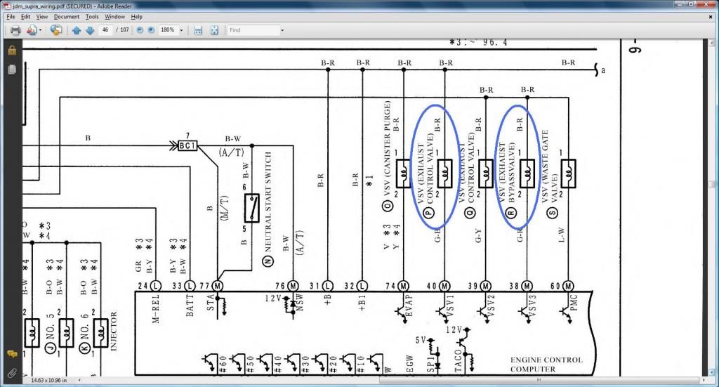
In the diagram above you don't see the connectivity of Pin 1 of VSV1 & VSV3 to Pin 2 of the Oxygen Sensor so am posting this diagram and you follow what is in Orange to prove that there is connectivity between them.
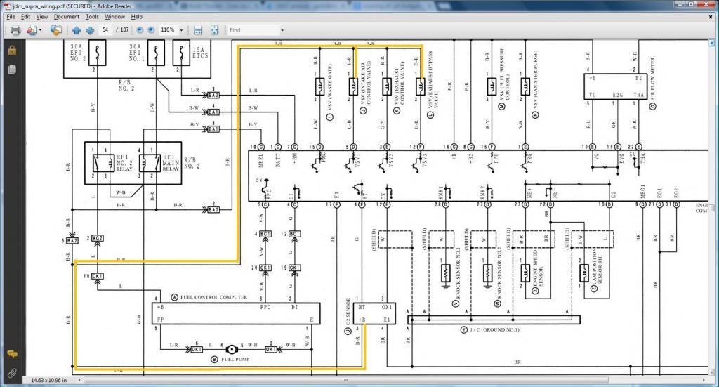
Do you remember that we have shown previously through the diagrams that Pin 2 of the Oxygen Sensor goes to (Pin 12 of the Data Link Connector & goes to ( SC3 IJ1-12 & EB2-1 & Short-4 , SC4 IJ1-12 & EB2-3 , MK4 EA3-3 )) . Since we have shown in the above picture that Pin 1 of VSV1 & VSV3 goes to Pin 2 of the Oxygen Sensor , I guess it goes without saying that Pin1 of VSV1 & VSV3 goes to (Pin 12 of the Data Link Connector & goes to ( SC3 IJ1-12 & EB2-1 & Short-4 , SC4 IJ1-12 & EB2-3 , MK4 EA3-3 ))
CONFUSING ? DON'T WORRY ABOUT IT THEN . AS I HAVE SAID ,YOU REALLY DON'T NEED THESE DIAGRAMS I AM POSTING
  !
!
*** Ignition Coils ***

In the diagram above we don't see the Pin 1 of all the Coil Plugs being connected to ( SC3 IJ1-7 , SC4 EB2-2 , MK4 IJ1-1 or IJ1-9) but we see them to be connected to Pin 1 of the Noise Filter and to Pin 2 of the 4 pin Igniter Connector. And we have proven this two pins to be connected to ( SC3 IJ1-7 , SC4 EB2-2 , MK4 IJ1-1 or IJ1-9) . Ergo , Pin 1 of all the Coil Plugs are connected to ( SC3 IJ1-7 , SC4 EB2-2 , MK4 IJ1-1 or IJ1-9) . Are you convinced ? If not , go over the previous diagrams .
*** VSV 1 & VSV2 ***
There are things I noticed on this diagram . 1) The VSV1 is labeled Exhaust Control Valve for which there is a duplicate which is VSV2 as you can see on the diagram. I checked the USDM Wiring Diagram Pin 40 is the Air Intake Control Valve so I labeled it as such. 2) On this diagram, you don't see Pin 1 of VSV1 connected to Pin 1 of VSV3 . On this one , just trust me
, they meet through another plug. 3) When I was probing my Aristo harness on these VSVs , looks to me their Pin 2 were interchanged on my harness . What I mean is Pin 2 of VSV1 was going to pin 38 of the 80 pin ECU connector and the Pin 2 of VSV3 was going to to pin 40 of the 80 pin ECU connector which is not according to the diagram below. I did check this diagram against the USDM diagram , pin numberings are correct so I am guessing someone played around with my actual Aristo harness VSV1 and VSV3 pins.
In the diagram above you don't see the connectivity of Pin 1 of VSV1 & VSV3 to Pin 2 of the Oxygen Sensor so am posting this diagram and you follow what is in Orange to prove that there is connectivity between them.

Do you remember that we have shown previously through the diagrams that Pin 2 of the Oxygen Sensor goes to (Pin 12 of the Data Link Connector & goes to ( SC3 IJ1-12 & EB2-1 & Short-4 , SC4 IJ1-12 & EB2-3 , MK4 EA3-3 )) . Since we have shown in the above picture that Pin 1 of VSV1 & VSV3 goes to Pin 2 of the Oxygen Sensor , I guess it goes without saying that Pin1 of VSV1 & VSV3 goes to (Pin 12 of the Data Link Connector & goes to ( SC3 IJ1-12 & EB2-1 & Short-4 , SC4 IJ1-12 & EB2-3 , MK4 EA3-3 ))
CONFUSING
? DON'T WORRY ABOUT IT THEN . AS I HAVE SAID ,YOU REALLY DON'T NEED THESE DIAGRAMS I AM POSTING !
Last edited by gerrb; 01-31-14 at 02:29 PM.