2jzGTE SCs - The Siblings of my Supra MKIV Toys
 01-14-14, 08:16 AM
#2116

Let us update our CHART
80 PIN ECU CONNECTOR
1
2
7 <--> Pin 1 of the Crankshaft Position Sensor CHECKED
10
20 <--> Pin 1 of the Injector No. 1 CHECKED
27 <--> Pin 2 of the Crankshaft Position Sensor CHECKED
30
38 <--> Pin 2 of the VSV3 CHECKED
39 <--> Pin 2 of the VSV2 CHECKED
40 <--> Pin 2 of the VSV1 CHECKED
41 <--> Pin 1 of the TPS <--> Pin 4 of the Sub-TPS CHECKED
42 <--> Pin 3 of the Sub-TPS CHECKED
43 <--> Pin 2 of the TPS CHECKED
44 <--> Pin 2 of the Water Temperature Sensor CHECKED
48 <--> Pin 3 of the O2 Sensor CHECKED
49 <--> Pin 1 of the Knock Sensor 1 CHECKED
50 <--> Pin 1 of the Knock Sensor 1 CHECKED
51
52 <--> Pin 7 of the 12 pin Igniter Connector CHECKED
53 <--> Pin 8 of the 12 pin igniter Connector CHECKED
54 <--> Pin 9 of the 12 pin igniter Connector CHECKED
55 <--> Pin 3 of the 12 pin igniter Connector CHECKED
56 <--> Pin 2 of the 12 pin Igniter Connector CHECKED
57 <--> Pin 1 of the 12 pin Igniter Connector CHECKED
58 <--> Pin 3 of the 4 pin Igniter Connector CHECKED
59
60 <--> Pin 2 of the VSVPMC CHECKED
63 <--> Pin 2 of the Sub-TPS CHECKED
64 <--> Pin 3 of the TPS CHECKED
65 <--> Pin 1 of the Water Temperature Sensor <--> Pin 4 of the TPS <--> Pin1 of the Sub-TPS CHECKED
69 <--> Rear Intake Manifold Ground CHECKED
70
71 <--> Pin 1 of the O2 Sensor CHECKED
74 <--> Pin 2 of the VSVEVAP CHECKED
79 <--> Rear Intake Manifold Ground CHECKED
80 <--> Rear Intake Manifold Ground CHECKED
4 PIN IGNITER CONNECTOR
1 <--> Pin 12 of Plug F of Aristo plug <--> ( Pin 19 of the Data Link Connector <--> ( SC3 IK1-8 , SC4 IK1-8 , MK4 ))
2 <--> Pin 6 of Plug F of Aristo plug <--> Pin 1 of the Noise Filter <--> ( SC3 IJ1-7 , SC4 EB2-2 , MK4 IJ1-1 or IJ1-9 )
3 <--> Pin 58 of the 80 pin ECU connector CHECKED
4 <--> Ground Connector on the Front Side of Intake Manifold <--> Pin 2 of the Noise filter Connector CHECKED
12 PIN IGNITER CONNECTOR
1 <--> Pin 57 of the 80 pin ECU connector CHECKED
2 <--> Pin 56 of the 80 pin ECU connector CHECKED
3 <--> Pin 55 of the 80 pin ECU connector CHECKED
4 <--> Pin 2 of the Ignition Coil Connector 3 CHECKED
5 <--> Pin 2 of the Ignition Coil Connector 2 CHECKED
6 <--> Pin 2 of the Ignition Coil Connector 1 CHECKED
7 <--> Pin 52 of the 80 pin ECU connector CHECKED
8 <--> Pin 53 of the 80 pin ECU connector CHECKED
9 <--> Pin 54 of the 80 pin ECU connector CHECKED
10 <--> Pin 2 of the Ignition Coil Connector 4 CHECKED
11 <--> Pin 2 of the Ignition Coil Connector 5 CHECKED
12 <--> Pin 2 of the Ignition Coil Connector 6 CHECKED
AC COMPRESSOR PLUG
1 <--> Pin 1 of Plug C of the Aristo Plug (should go to (SC3 EB1-7 & II1-1 , SC4 ED1-8 then to EB1-7 & II1-1 , MK4 II1-26 ))
2 <--> Pin 2 of Plug C of the Aristo Plug (should go to (SC3 II1-4 , SC4 ED1-4 then to II1-4 , MK4 II1-20 ))
4 <--> Pin 5 of Plug C of the Aristo Plug (should go to (SC3 EB1-1 , SC4 ED2-1 then to EB1-1 , MK4 EA1-1 & II1-10 ))
CRANKSHAFT POSITION SENSOR
1 <--> Pin 7 of the 80 pin ECU Connector CHECKED
2 <--> Pin 27 of the 80 pin ECU Connector CHECKED
DIAGNOSTIC PORT
1 (FP) <--> Pin 15 of Plug C of the Big Gray Aristo Plug (should go to (SC3 IJ1-1 , SC4 IJ1-1 , MK4 IJ1-8 ))
2 (W) <--> Pin 2 of Plug E of the Big Gray Aristo Plug (should go to Pin 6 of the 40 pin ECU Connector & to (SC3 IK2-9 , SC4 IK2-9 , MK4 II1-15 ))
3 (E1) <--> Pin 11 of Plug F of the Big Gray Aristo Plug (should go to Rear Intake Manifold Ground & to (SC3 Pin 69,79,80 of the 80 pin ECU Connector , SC4 Pin 69,79,80 of the 80 pin ECU Connector , MK4 IJ1-18 ))
4 (OX1)<--> Pin 48 of the 80 pin ECU Connector
5 (AB) <--> Pin 4 of Plug D of the Big Gray Aristo Plug
6 (OP1)<--> Pin 10 of Plug D of the Big Gray Aristo Plug
7 (CCo)<--> Pin 8 of Plug D of the Big Gray Aristo Plug
8 (TE1) <--> Pin 4 of Plug F of the Big Gray Aristo Plug(should go to Pin 20 of the 40 pin ECU Connector & to ( SC3 IK1-4 , SC4 IK1-4 , MK4 IJ1-5 ))
9 (TE2) <--> Pin 7 of Plug E of the Big Gray Aristo Plug (should go to Pin 19 of the 40 pin ECU Connector & to ( SC3 IK1-2 , SC4 IK1-2 , MK4 IJ1-17 ))
11 (TC)<--> Pin 6 of Plug E of the Big Gray Aristo Plug
12 (+B)<--> Pin 3 of Plug E of the Big Gray Aristo Plug (should go to (SC3 IJ1-12 & EB2-1 & Short-4 & Pin 2 of O2 Sensor , SC4 IJ1-12 & EB2-3 & Pin 2 of O2 Sensor , MK4 EA3-3 & Pin 31 of 40 pin ECU Connector ))
13 (VF1)<-->Pin 10 of Plug F of the Big Gray Aristo Plug (should go to Pin 29 of the 80 pin ECU Connector & to ( SC3 IK1-3 , SC4 IK1-3 , MK4 IJ1-13 ))
16 (TS)<--> Pin 5 of Plug F of the Big Gray Aristo Plug
18 (TEM)<--> Pin 5 of Plug D of the Big Gray Aristo Plug
19 (IG-) <--> Pin 1 of the 4 pin Igniter Connector
22 (WA) <--> PIn 7 of Plug D of the Big Gray Aristo Plug
23 (WB) <--> Pin 11 of Plug D of the Big Gray Aristo Plug
GROUND - Front Intake Manifold
1 <--> Pin 2 of Noise Filter <--> Pin 4 of the 4 pin ECU CONNECTOR CHECKED
GROUND - Rear Intake Manifold
1 <--> Pin 69 <---> Pin 79 <--> Pin 80 of the 80 pin ECU Connector CHECKED
IGNITION COIL 1
1 <--> Pin 1 of the Noise Filter <--> Pin 2 of the 4 pin Igniter Connector <--> Pin 1 of Ignition Coil 2,3,4,5,6 <-->( SC3 IJ1-7 , SC4 EB2-2 , MK4 IJ1-1 or IJ1-9 )
2 <--> Pin 6 of the 12 Pin Igniter Connector CHECKED
IGNITION COIL 2
1 <--> Pin 1 of the Noise Filter <--> Pin 2 of the 4 pin Igniter Connector <--> Pin 1 of Ignition Coil 1,3,4,5,6 <-->( SC3 IJ1-7 , SC4 EB2-2 , MK4 IJ1-1 or IJ1-9 )
2 <--> Pin 5 of the 12 Pin Igniter Connector CHECKED
IGNITION COIL 3
1 <--> Pin 1 of the Noise Filter <--> Pin 2 of the 4 pin Igniter Connector <--> Pin 1 of Ignition Coil 1,2,4,5,6 <-->( SC3 IJ1-7 , SC4 EB2-2 , MK4 IJ1-1 or IJ1-9 )
2 <--> Pin 4 of the 12 Pin Igniter Connector CHECKED
IGNITION COIL 4
1 <--> Pin 1 of the Noise Filter <--> Pin 2 of the 4 pin Igniter Connector <--> Pin 1 of Ignition Coil 1,2,3,5,6 <-->( SC3 IJ1-7 , SC4 EB2-2 , MK4 IJ1-1 or IJ1-9 )
2 <--> Pin 10 of the 12 Pin Igniter Connector CHECKED
IGNITION COIL 5
1 <--> Pin 1 of the Noise Filter <--> Pin 2 of the 4 pin Igniter Connector <--> Pin 1 of Ignition Coil 1,2,3,4,6 <-->( SC3 IJ1-7 , SC4 EB2-2 , MK4 IJ1-1 or IJ1-9 )
2 <--> Pin 11 of the 12 Pin Igniter Connector CHECKED
IGNITION COIL 6
1 <--> Pin 1 of the Noise Filter <--> Pin 2 of the 4 pin Igniter Connector <--> Pin 1 of Ignition Coil 1,2,3,4,5 <-->( SC3 IJ1-7 , SC4 EB2-2 , MK4 IJ1-1 or IJ1-9 )
2 <--> Pin 12 of the 12 Pin Igniter Connector CHECKED
INJECTOR NO. 1
1 <--> Pin 20 of the 80 pin ECU Connector
2 <--> (should go to (SC3 IJ1-7 or IJ1-3 & short 3 & short 5 , SC40 EB2-2 , MK4 IJ1-9))
KNOCK SENSOR 1
1 <--> Pin 50 of the 80 pin ECU Connector CHECKED
KNOCK SENSOR 2
1 <--> Pin 49 of the 80 pin ECU Connector CHECKED
NOISE FILTER
1 <--> Pin 2 of the 4 pin Igniter Connector <--> ( SC3 IJ1-7, SC4 EB2-2 , MK4 IJ1-1 or IJ1-9 )
2 <--> Ground Connector on the Front Side of Intake Manifold <--> Pin 4 of the 4 pin Igniter Connector CHECKED
OIL LEVEL SENSOR PLUG
1 <--> Pin 1 of Plug D of Big Gray Aristo Plug (should go to (SC3 IK2-10 , SC4 IK2-10 , MK4 II1-33 ))
2 <--> Pin 7 of Plug F of Big Gray Aristo Plug(should go to ( SC3 / SC4 / MK4 Rear Intake Manifold Ground for all ))
OIL PRESSURE PLUG
1 <--> Pin 8 of Plug F of the Aristo Plug (should go to ( SC3 IK1-20 , SC4 IK1-20 , MK4 II1-25 ))
STARTER
1 <--> Pin 1 of Plug F of Big Gray Aristo Plug (should go to (SC3 EB2-1 , SC4 ED2-2 then EB2-1 , MK4 EA3-1 ))
THROTTLE POSITION SENSOR
1 <--> Pin 41 of the 80 pin ECU Connector CHECKED
2 <--> Pin 43 of the 80 pin ECU Connector CHECKED
3 <--> Pin 64 of the 80 pin ECU Connector CHECKED
4 <--> Pin 65 of the 80 pin ECU Connector CHECKED
WATER TEMPERATURE SENSOR
1 <--> Pin 65 of the 80 pin ECU Connector CHECKED
2 <--> Pin 44 of the 80 pin ECU Connector CHECKED
WATER TEMPERATURE GAUGE SENDER
1 <--> Pin 9 of Plug F of the Big Gray Aristo Plug (should go to SC3 IK1-9 , SC4 IK1-9 & Short-3 , MK4 II1-19 )
The following plugs are necessary only if you are going stock 2jzgte setup
OXYGEN SENSOR (O2)
1 <--> Pin 71 of the 80 pin ECU Connector CHECKED
2 <--> Pin 3 of Plug E of Aristo Plug <-> (Pin 12 of the Data Link Connector <--> ( SC3 IJ1-12 & EB2-1 & Short-4 , SC4 IJ1-12 & EB2-3 , MK4 EA3-3 ))
3 <--> Pin 48 of the 80 pin ECU Connector CHECKED
VSV1 ( Air Intake Control Valve )
1 <--> Pin 2 of the O2 Sensor <--> Pin 1 of the VSV3 <-> (Pin 12 of the Data Link Connector <--> ( SC3 IJ1-12 & EB2-1 & Short-4 , SC4 IJ1-12 & EB2-3 , MK4 EA3-3 ))
2 <--> Pin 40 of the 80 pin ECU Connector CHECKED
VSV2 ( Exhaust Control Valve )
1 <--> Pin 1 of VSV1 , VSV3 , VSVPMC <--> Pin 2 of the O2 Sensor <--> Pin 1 of the VSV3 <-> (Pin 12 of the Data Link Connector <--> ( SC3 IJ1-12 & EB2-1 & Short-4 , SC4 IJ1-12 & EB2-3 , MK4 EA3-3 ))
2 <--> Pin 39 of the 80 pin ECU Connector CHECKED
VSV3( Exhaust Bypass Valve )
1 <--> Pin 2 of the O2 Sensor <-->Pin 1 of the VSV1 <-> (Pin 12 of the Data Link Connector <--> ( SC3 IJ1-12 & EB2-1 & Short-4 , SC4 IJ1-12 & EB2-3 , MK4 EA3-3 ))
2 <--> Pin 38 of the 80 pin ECU Connector CHECKED
VSVEVAP ( Canister Purge )
1 <--> Pin 1 of VSV1 , VSV2 , VSV3 , VSVPMC <--> (Pin 12 of the Data Link Connector <--> ( SC3 IJ1-12 & EB2-1 & Short-4 , SC4 IJ1-12 & EB2-3 , MK4 EA3-3 ))
2 <--> Pin 74 of the 80 pin ECU Connector
VSVPMC ( Waste Gate Valve )
1 <--> Pin 1 of VSV1 , VSV2 , VSV3 <--> Pin 2 of the O2 Sensor <--> Pin 1 of the VSV3 <-> (Pin 12 of the Data Link Connector <--> ( SC3 IJ1-12 & EB2-1 & Short-4 , SC4 IJ1-12 & EB2-3 , MK4 EA3-3 ))
2 <--> Pin 60 of the 80 pin ECU Connector CHECKED
The following plugs maybe kept or deleted depending on your seup
2) Sub-Throttle Position Sensor
1 <--> Pin 65 of the 80 pin ECU Connector CHECKED
2 <--> Pin 63 of the 80 pin ECU Connector CHECKED
3 <--> Pin 42 of the 80 pin ECU Connector CHECKED
4 <--> Pin 41 of the 80 pin ECU Connector CHECKED
The following plugs are usually deleted
Throttle Motor Valve
1 <--> Pin 8 of Plug C of Big Gray Aristo Plug
2 <--> Pin 11 of Plug C of Big Gray Aristo Plug
3 <--> Pin 7 of Plug C of Big Gray Aristo Plug
4 <--> Pin 4 of Plug C of Big Gray Aristo Plug
5 <--> Pin 6 of Plug C of Big Gray Aristo Plug
6 <--> Pin 3 of Plug C of Big Gray Aristo Plug
The following plug definitely will be deleted but its wires go to different body plugs or 40 pin ECU Connector or can be used for future needs
BIG GRAY ARISTO PLUG
PLUG C
1 <--> (SC3 EB1-7 & II1-1 , SC4 ED1-8 then to EB1-7 & II1-1 , MK4 II1-26 ))
2 <-->(should go to (SC3 II1-4 , SC4 ED1-4 then to II1-4 , MK4 II1-20 ))
3 <--> Extra Wire for future use CHECKED
4 <--> Extra Wire for future use CHECKED
5 <--> (should go to (SC3 EB1-1 , SC4 ED2-1 then to EB1-1 , MK4 EA1-1 & II1-10 ))
6 <--> Extra Wire for future use CHECKED
7 <--> Extra Wire for future use CHECKED
8 <--> Extra Wire for future use CHECKED
11 <--> Extra Wire for future use CHECKED
13 <--> Extra Wire for future use CHECKED
15 <--> Pin 1 (FP) of Diagnostic Port goes (should go to (SC3 IJ1-1 , SC4 IJ1-1 , MK4 IJ1-8 ))
PLUG D
1 <--> (should go to (SC3 IK2-10 , SC4 IK2-10 , MK4 II1-33 ))
4 <--> Pin 5 (AB) of Diagnostic Port
5 <--> Pin 18 (TEM) of Diagnostic Port
6 <--> Pin 63 of the 80 pin ECU Connector (Is still needed ????? remains to be seen during the merge process)
7 <--> Pin 22 (WA) of Diagnostic Port
8 <--> Pin 7 (CCo) of Diagnotic Port
9 <--> Extra Wire for future use CHECKED
10<-->Pin 6 (OP1) of Diagnostic Port
11<-->Pin 23 (WB) of Diagnostic Port
PLUG E
2 <--> Pin 2 (W) of Diagnostic Port (should go to Pin 6 of the 40 pin ECU Connector & to (SC3 IK2-9 , SC4 IK2-9 , MK4 II1-15 ))
3 <--> Pin 2 of Oxygen Sensor <--> (Pin 12 of the Data Link Connector <--> ( SC3 IJ1-12 & EB2-1 & Short-4 , SC4 IJ1-12 & EB2-3 , MK4 EA3-3 ))
4 <--> Pin 12 (+B) of Diagnostic Port (should go to (SC3 IJ1-12 & EB2-1 & Short-4 & Pin 2 of O2 Sensor , SC4 IJ1-12 & EB2-3 & Pin 2 of O2 Sensor , MK4 EA3-3 & Pin 31 of 40 pin ECU Connector )
6 <--> Pin 11 (TC) of Diagnostic Port
7 <--> Pin 9 (TE2) of Diagnostic Port (should go to Pin 19 of the 40 pin ECU Connector & to ( SC3 IK1-2 , SC4 IK1-2 , MK4 IJ1-17 ))
PLUG F
4 <--> Pin 8 (TE1) of Diagnostic Port ((should go to Pin 20 of the 40 pin ECU Connector & to ( SC3 IK1-4 , SC4 IK1-4 , MK4 IJ1-5 ))
5 <--> Pin 16 (TS) of Diagnostic Port
6 <--> Pin 1 of the Noise Filter <--> ( SC3 IJ1-7 , SC4 EB2-2 , MK4 IJ1-1 or IJ1-9 )
7 <--> (should go to ( SC3 / SC4 / MK4 Rear Intake Manifold Ground for all ))
8 <--> (should go to ( SC3 IK1-20 , SC4 IK1-20 , MK4 II1-25 ))
9 <--> Pin 1 of the Water Temperature Gauge Sender <--> ( SC3 IK1-9 , SC4 IK1-9 & Short-3 , MK4 II1-19 )
10<--> Pin 13 (VF1) of Diagnostic Port (should go to Pin 29 of the 80 pin ECU Connector & to ( SC3 IK1-3 , SC4 IK1-3 , MK4 IJ1-13 ))
11<--> Pin 3 (E1) of Diagnostic Port (should go to Rear Intake Manifold Ground & to (SC3 Pin 69,79,80 of the 80 pin ECU Connector , SC4 Pin 69,79,80 of the 80 pin ECU Connector , MK4 IJ1-18 ))
12 <--> ( Pin 19 of the Data Link Connector & to ( SC3 IK1-8 , SC4 IK1-8 , MK4 ))
Last edited by gerrb; 01-31-14 at 06:14 AM.
 01-14-14, 08:48 AM
#2117
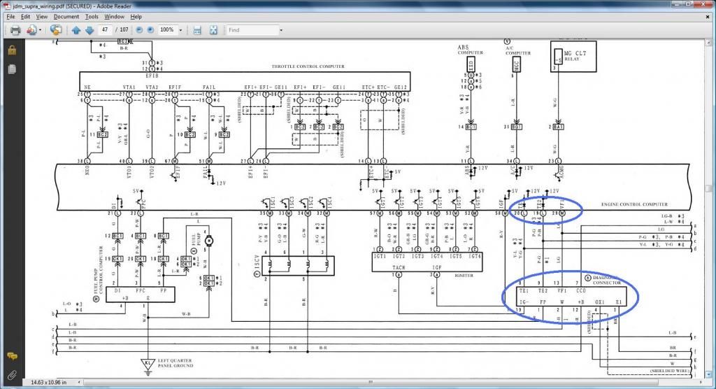
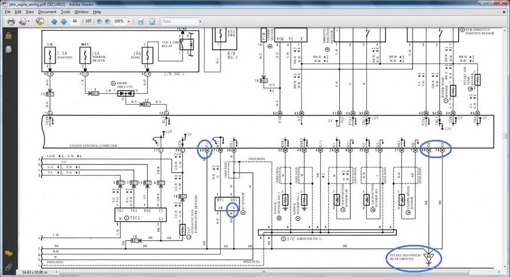
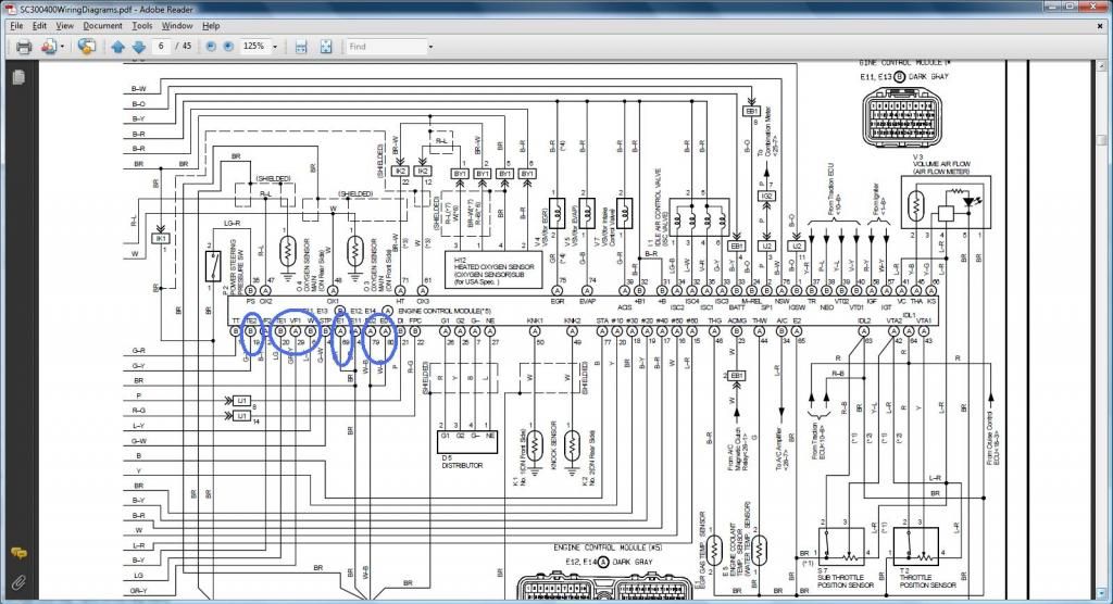
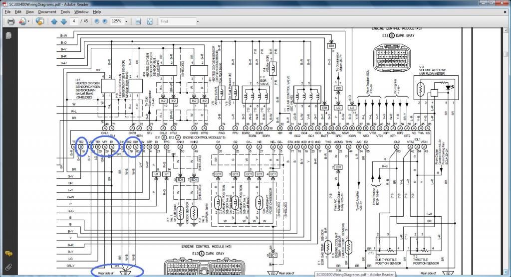
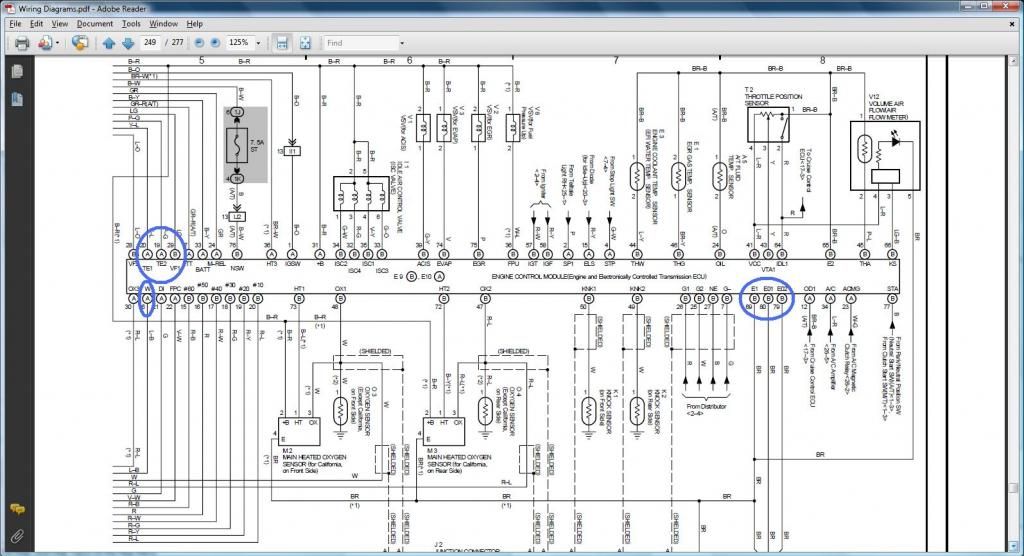
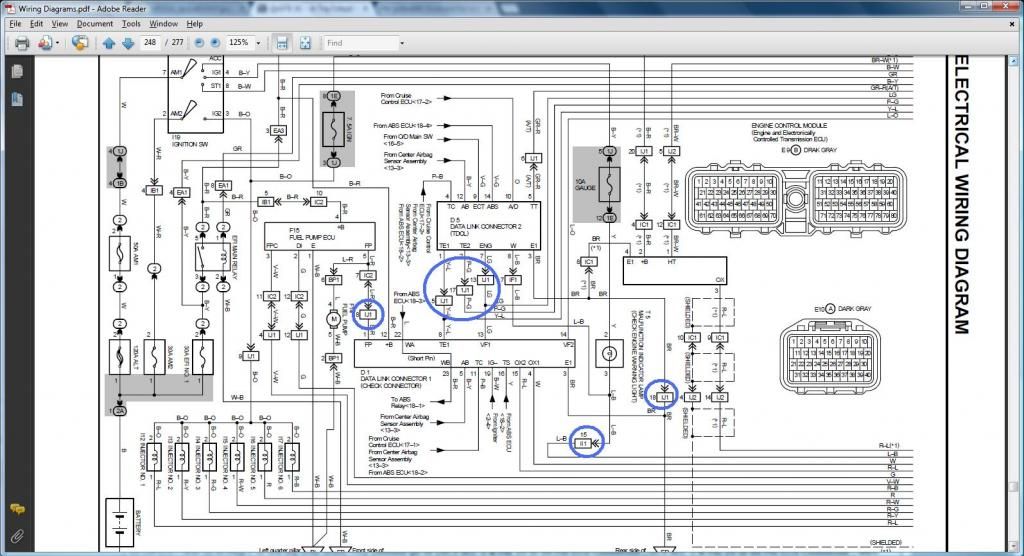
DIAGRAMS TO VERIFY PIN NUMBERING & WHERE THE WIRE GOES
*** KNOCK SENSOR 2 ***
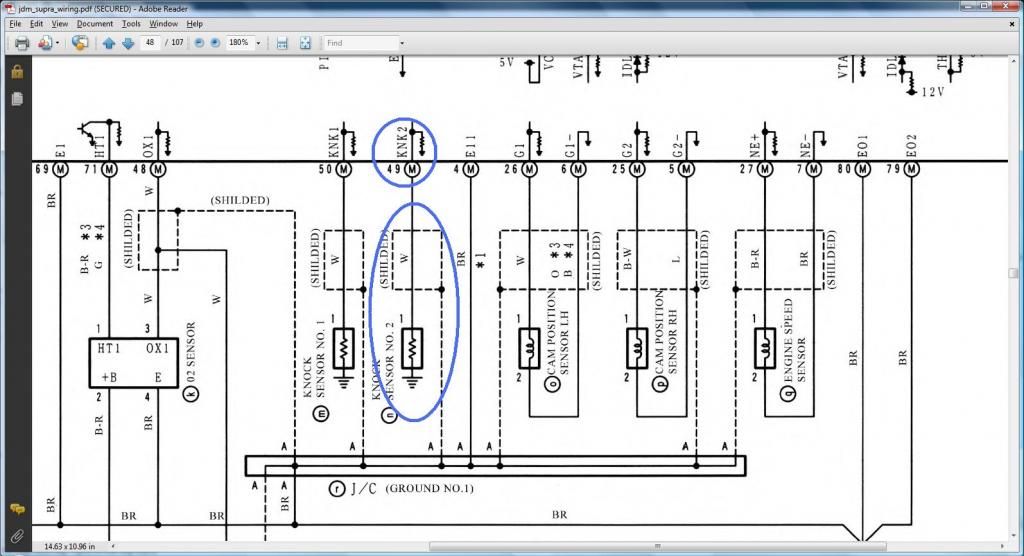
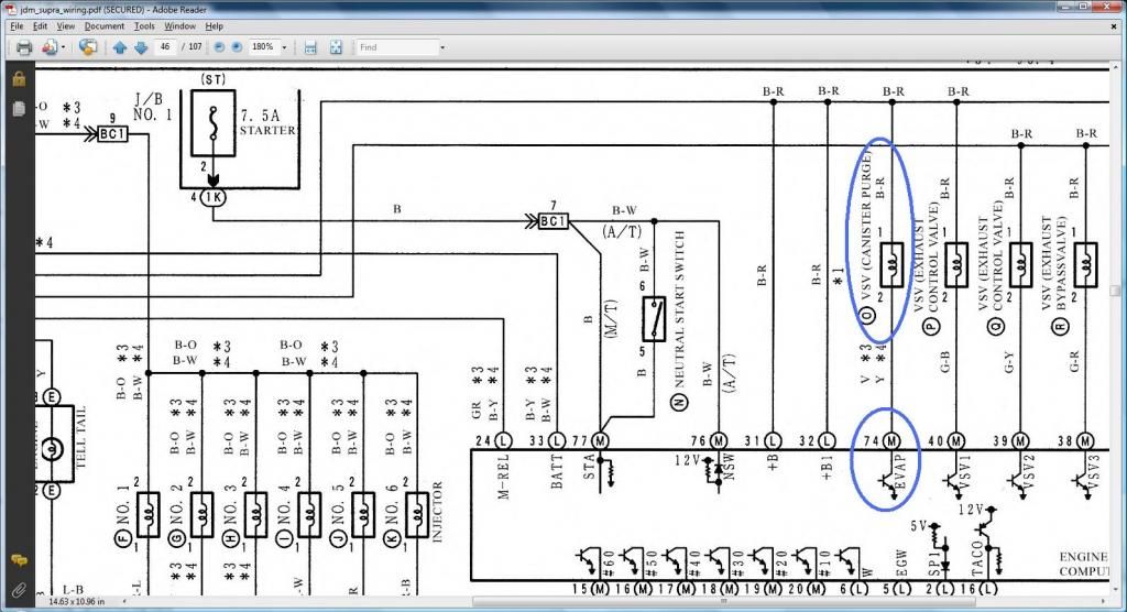
*** VSVEVAP ***
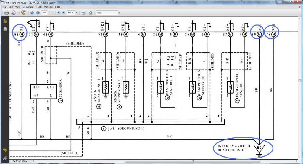
*** REAR INTAKE MANIFOLD GROUND ***
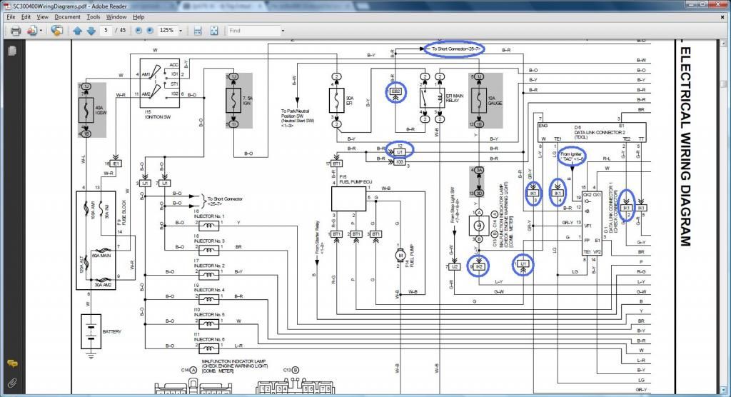
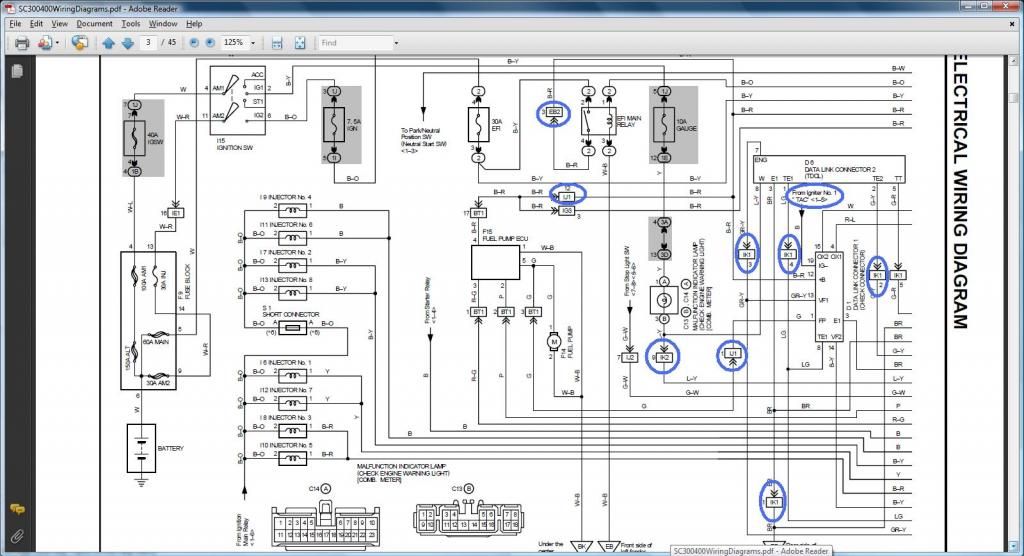
DIAGRAMS TO VERIFY WHERE A WIRE SHOULD GO IN A SC300, SC400, MKIV
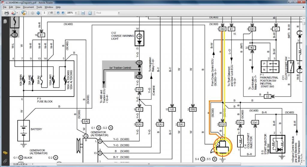
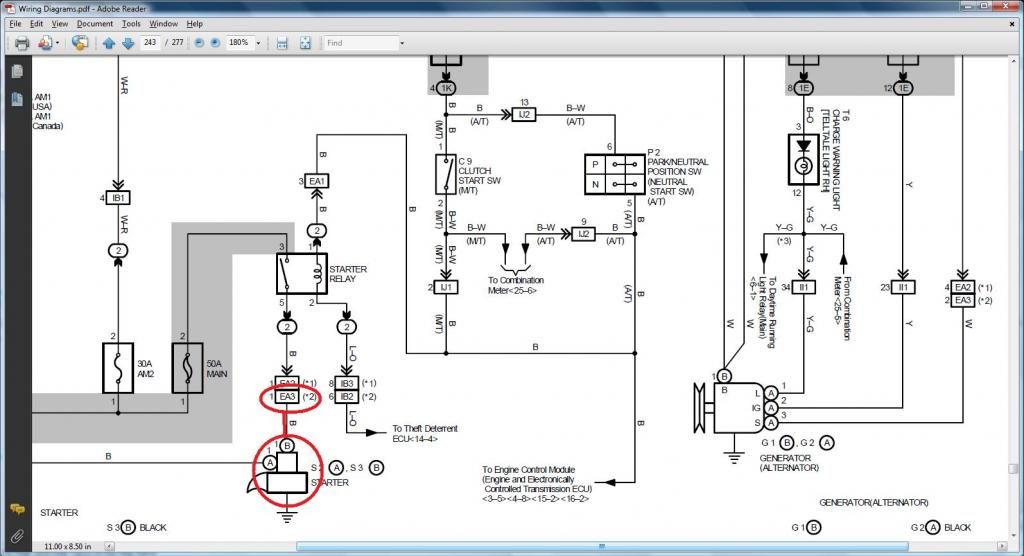
*** STARTER ***
Pin 1 of the Starter (should go to (SC3 EB2-1 , SC4 ED2-2 then EB2-1 , MK4 EA3-1 ))
SC300 - Orange /. SC400 - Yellow
MKIV
*** VSVEVAP ***
We have proven that Pin 1 of VSV1 ( should go to Pin 12 of the Data Link Connector & to ( SC3 IJ1-12 & EB2-1 & Short-4 , SC4 IJ1-12 & EB2-3 , MK4 EA3-3 )) . Since Pin 1 of VSVEVAP goes to Pin 1 of VSV1 , ERGO Pin 1 of VSVEVAP ( should go to Pin 12 of the Data Link Connector & to ( SC3 IJ1-12 & EB2-1 & Short-4 , SC4 IJ1-12 & EB2-3 , MK4 EA3-3 ))
Thus I am not showing those diagrams again.
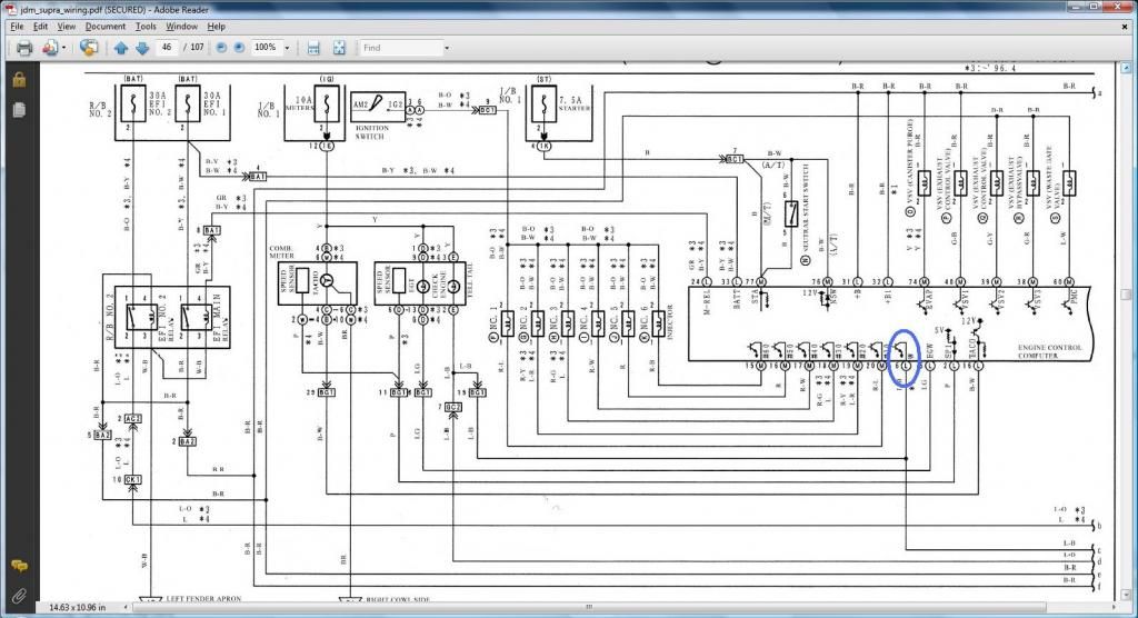
*** DIAGNOSTIC PORT ***
Pin 2 (W) of the Diagnostic Port should go to Pin 6 of the 40 pin ECU Connector & to ( SC3 IK2-9 , SC4 IK2-9 , MK4 II1-15 )
Pin 8 (TE1) of the Diagnostic Port should go to Pin 20 of the 40 pin ECU Connector & to ( SC3 IK1-4 , SC4 IK1-4 , MK4 IJ1-5 )
Pin 9 (TE2) of the Diagnostic Port should go to Pin 19 of the 40 pin ECU Connector & to ( SC3 IK1-2 , SC4 IK1-2 , MK4 IJ1-17 )
Pin 13 (VF1) of the Diagnostic Port should go to Pin 29 of the 80 pin ECU Connector & to ( SC3 IK1-3 , SC4 IK1-3 , MK4 IJ1-13 )
Pin 1 (FP) of the Diagnostic Port (should go to (SC3 IJ1-1 , SC4 IJ1-1 , MK4 IJ1-8 ))
Pin 3 (E1) of the Diagnostic Port (should go to Rear Intake Manifold Ground & to (SC3 Pin 69,79,80 of the 80 pin ECU Connector , SC4 Pin 69,79,80 of the 80 pin ECU Connector , MK4 IJ1-18 ))
Pin 12 (+B) of the Diagnostic Port (should go to (SC3 IJ1-12 & EB2-1 & Short-4 & Pin 2 of O2 Sensor , SC4 IJ1-12 & EB2-3 & Pin 2 of O2 Sensor , MK4 EA3-3 & Pin 31 of 40 pin ECU Connector ))
Read this diagram being on the left of the next diagram so you see continuous flow of current .
Read this diagram being on the right of the previous diagram so you see continuous flow of current
SC300 Read this diagram being on the right of the next diagram so you see continuous flow of current
SC400 Read this diagram being on the right of the next diagram so you see continuous flow of current
MKIV Read this diagram being on the right of the next diagram so you see continuous flow of current
*** KNOCK SENSOR 2 ***

*** VSVEVAP ***

*** REAR INTAKE MANIFOLD GROUND ***

DIAGRAMS TO VERIFY WHERE A WIRE SHOULD GO IN A SC300, SC400, MKIV
*** STARTER ***
Pin 1 of the Starter (should go to (SC3 EB2-1 , SC4 ED2-2 then EB2-1 , MK4 EA3-1 ))
SC300 - Orange /. SC400 - Yellow

MKIV

*** VSVEVAP ***
We have proven that Pin 1 of VSV1 ( should go to Pin 12 of the Data Link Connector & to ( SC3 IJ1-12 & EB2-1 & Short-4 , SC4 IJ1-12 & EB2-3 , MK4 EA3-3 )) . Since Pin 1 of VSVEVAP goes to Pin 1 of VSV1 , ERGO Pin 1 of VSVEVAP ( should go to Pin 12 of the Data Link Connector & to ( SC3 IJ1-12 & EB2-1 & Short-4 , SC4 IJ1-12 & EB2-3 , MK4 EA3-3 ))
Thus I am not showing those diagrams again.
*** DIAGNOSTIC PORT ***
Pin 2 (W) of the Diagnostic Port should go to Pin 6 of the 40 pin ECU Connector & to ( SC3 IK2-9 , SC4 IK2-9 , MK4 II1-15 )
Pin 8 (TE1) of the Diagnostic Port should go to Pin 20 of the 40 pin ECU Connector & to ( SC3 IK1-4 , SC4 IK1-4 , MK4 IJ1-5 )
Pin 9 (TE2) of the Diagnostic Port should go to Pin 19 of the 40 pin ECU Connector & to ( SC3 IK1-2 , SC4 IK1-2 , MK4 IJ1-17 )
Pin 13 (VF1) of the Diagnostic Port should go to Pin 29 of the 80 pin ECU Connector & to ( SC3 IK1-3 , SC4 IK1-3 , MK4 IJ1-13 )
Pin 1 (FP) of the Diagnostic Port (should go to (SC3 IJ1-1 , SC4 IJ1-1 , MK4 IJ1-8 ))
Pin 3 (E1) of the Diagnostic Port (should go to Rear Intake Manifold Ground & to (SC3 Pin 69,79,80 of the 80 pin ECU Connector , SC4 Pin 69,79,80 of the 80 pin ECU Connector , MK4 IJ1-18 ))
Pin 12 (+B) of the Diagnostic Port (should go to (SC3 IJ1-12 & EB2-1 & Short-4 & Pin 2 of O2 Sensor , SC4 IJ1-12 & EB2-3 & Pin 2 of O2 Sensor , MK4 EA3-3 & Pin 31 of 40 pin ECU Connector ))
Read this diagram being on the left of the next diagram so you see continuous flow of current .


Read this diagram being on the right of the previous diagram so you see continuous flow of current

SC300 Read this diagram being on the right of the next diagram so you see continuous flow of current


SC400 Read this diagram being on the right of the next diagram so you see continuous flow of current


MKIV Read this diagram being on the right of the next diagram so you see continuous flow of current


Last edited by gerrb; 01-31-14 at 05:56 AM.
01-14-14, 09:02 AM
#2118
Let us work on the plugs for the auto transmission . You either keep them if your swap will be using an auto transmission , remove plugs and wires if you will be using a manual transmission OR keep the wires so you can re-use them for something else in the future.
The INFO you need so you can do THE DRILL
1) O/D Direct Clutch Speed Sensor (O/D)
Pin 1 of O/D goes to Pin 1 of 80 pin ECU Connector
Pin 2 of O/D goes to Pin 21 of 80 pin ECU Connector
2) Transmission Solenoid (ECT Solenoid)
Pin 1 of Transmission Solenoid goes to Pin 31 of 80 pin ECU Connector
Pin 2 of Transmission Solenoid goes to Pin 3 of Plug E of the Big Aristo Plug (should go to (Pin 12 of the Data Link Connector & to ( SC3 IJ1-12 & EB2-1 & Short-4 , SC4 IJ1-12 & EB2-3 , MK4 EA3-3 )))
Pin 3 of Transmission Solenoid goes to Pin 3 of Plug E of the Big Aristo Plug (should go to (Pin 12 of the Data Link Connector & to ( SC3 IJ1-12 & EB2-1 & Short-4 , SC4 IJ1-12 & EB2-3 , MK4 EA3-3 )))
Pin 4 of Transmission Solenoid goes to Pin 10 of 80 pin ECU Connector
Pin 5 of Transmission Solenoid goes to Pin 12 of 80 pin ECU Connector
Pin 6 of Transmission Solenoid goes to Pin 13 of 80 pin ECU Connector
Pin 7 of Transmission Solenoid goes to Pin 14 of 80 pin ECU Connector
Pin 8 of Transmission Solenoid goes to Pin 9 of 80 pin ECU Connector
3) A/T Rotation Sensor (Speed Sensor 2)
Pin 1 of A/T Rotation Sensor goes to Pin 23 of 80 pin ECU Connector
Pin 2 of A/T Rotation Sensor goes to Pin 3 of 80 pin ECU Connector
4) Speed Sensor 1
Pin 1 of Speed Sensor 1 goes to Pin 14 of Plug F of the Big Aristo Plug (Remove from Aristo plug and needs to go to a body plug)
Pin 2 of Speed Sensor 1 goes to Pin 3 of Plug F of the Big Aristo Plug (Remove from Aristo plug and needs to go to a body plug)
Pin 3 of Speed Sensor 1 goes to Pin 2 of Plug F of the Big Aristo Plug (Remove from Aristo plug and needs to go to a body plug)
5) A/T Fluid Temp Sensor
Pin 1 of A/T Fluid Temp Sensor goes to Pin 65 of 80 pin ECU Connector
Pin 2 of A/T Fluid Temp Sensor goes to Pin 24 of 80 pin ECU Connector
6) A/T Indicator Switch
Pin 2 of A/T Indicator Switch goes to Pin 9 of Plug E of the Big Aristo Plug (should go to Pin 9 of the 40 pin ECU Connector & to ( SC3 IK1-16 , SC4 IK1-16 , MK4 II1-17 ))
Pin 3 of A/T Indicator Switch goes to Pin 10 of Plug E of the Big Aristo Plug (should go to Pin 10 of the 40 pin ECU Connector & to ( SC3 IK1-17 , SC4 IK1-17 , MK4 II1-27 ))
Pin 4 of A/T Indicator Switch goes to Pin 14 of Plug E of the Big Aristo Plug (should go to ( SC3 IJ1-10 , SC4 IJ1-10 , MK4 II1-23 ))
Pin 5 of A/T Indicator Switch goes to Pin 12 of Plug E of the Big Aristo Plug
Pin 6 of A/T Indicator Switch goes to Pin 5 of Plug E of the Big Aristo Plug
Pin 7 of A/T Indicator Switch goes to Pin 4 of Plug E of the Big Aristo Plug (should go to ( SC3 IK1-12 , SC4 IK1-12 , MK4 II1-7 ))
Pin 8 of A/T Indicator Switch goes to Pin 13 of Plug E of the Big Aristo Plug (should go to Pin 7 of the 40 pin ECU Connector & to ( SC3 IK1-11 , SC4 IK1-11 , MK4 II1-36 ))
Pin 9 of A/T Indicator Switch goes to Pin 11 of Plug E of the Big Aristo Plug (should go to ( SC3 IK1-14 , SC4 IK1-14 , MK4 II1-18 ))
Pin 10 of A/T Indicator Switch goes to Pin 8 of Plug E of the Big Aristo Plug (should go to ( SC3 IK1-13 , SC4 IK1-13 , MK4 II1-1 ))
Guys , time to do THE DRILL .
Last edited by gerrb; 02-05-14 at 01:49 PM.
01-14-14, 09:09 AM
#2119
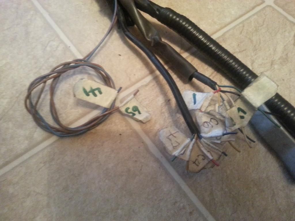
On Aaron's harness, started taking out the auto transmission plugs since he will be on an R154 . Here , I am taking out the wires of the A/T shifter plug. 3 of those wires are T'ed and need to be cut on the T and leave the pins on the Big Gray Aristo plug for now.
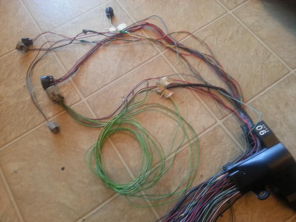
A/T shifter plug removed
This is what is left on that area for Aaron's harness who is on R154. Am sure you know by now , am a sucker of extra wires so I kept a couple of them there and besides you will have to wire a plug to your manual transmission for a switch (Hint : back up light ) . Make sure you label all extra wires end to end so you know which is which.
At this point , basically nothing left on the Big Gray Aristo Plug. Those are pins / wires that have Ts on other plugs. The only one without is that big wire that goes to the starter. But still all those wires will have to go to other plugs later so I am leaving them there for now

A/T shifter plug removed

This is what is left on that area for Aaron's harness who is on R154. Am sure you know by now , am a sucker of extra wires so I kept a couple of them there and besides you will have to wire a plug to your manual transmission for a switch (Hint : back up light ) . Make sure you label all extra wires end to end so you know which is which.

At this point , basically nothing left on the Big Gray Aristo Plug. Those are pins / wires that have Ts on other plugs. The only one without is that big wire that goes to the starter. But still all those wires will have to go to other plugs later so I am leaving them there for now

Last edited by gerrb; 01-30-14 at 03:00 PM.
01-14-14, 09:40 AM
#2120
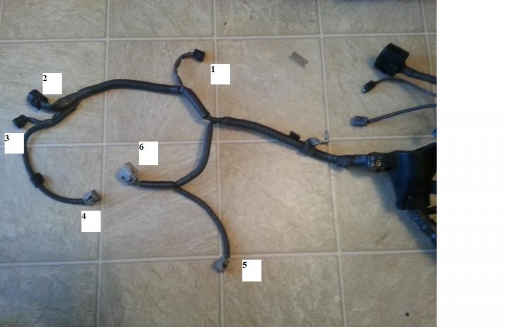
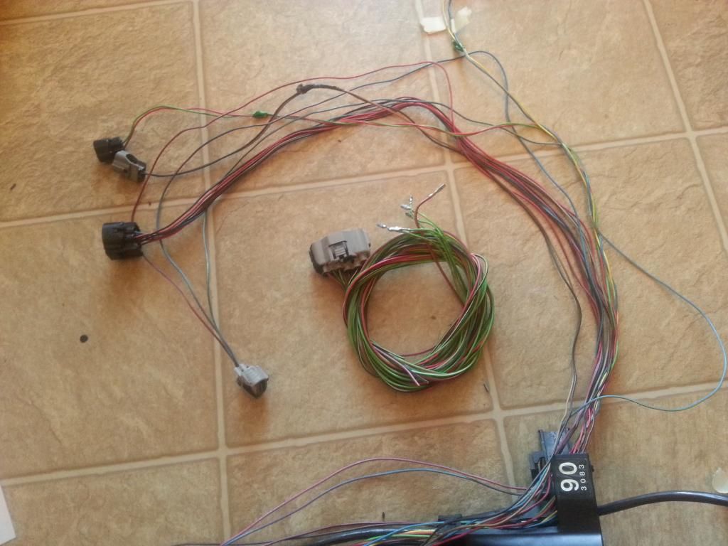
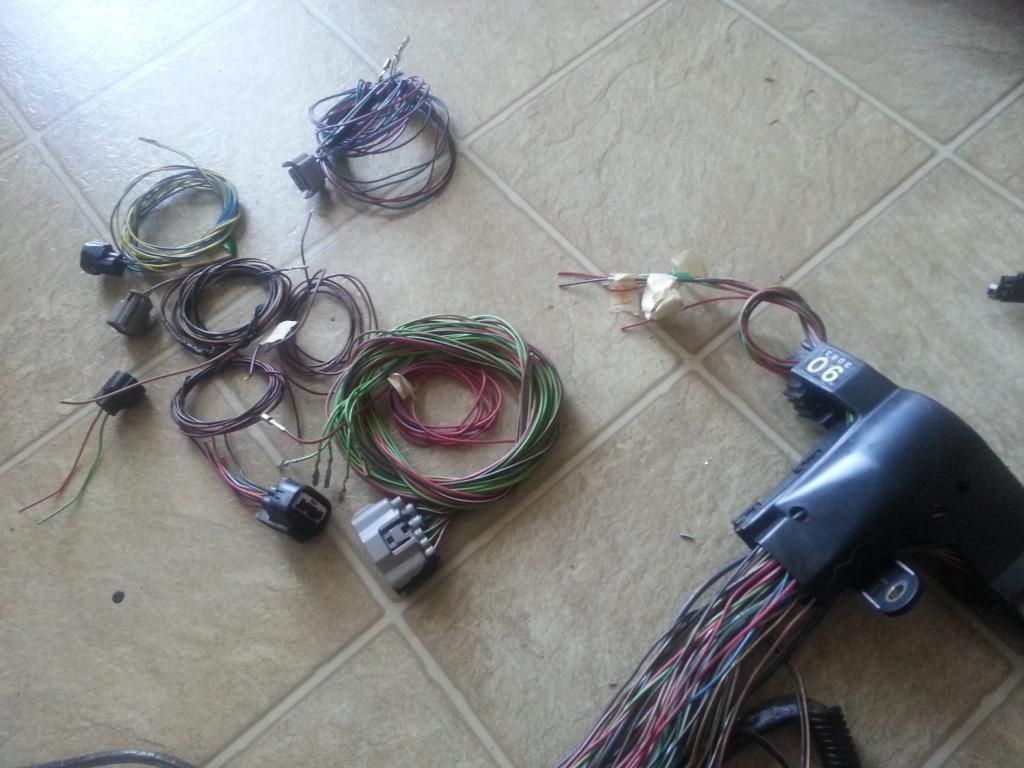
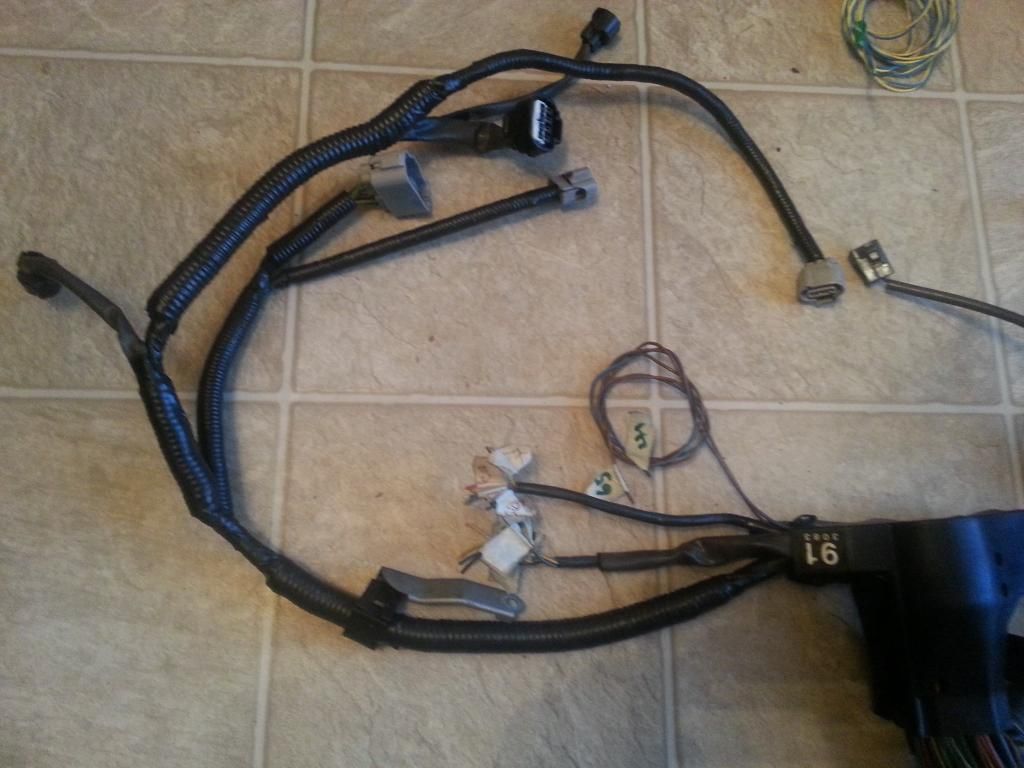
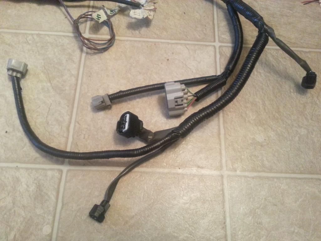
Well , if you recall we were working on these plugs on the 2jzgte harness.. that portion where we have the 5 injectors . In my case , I have already rewrapped them and would just put corrugated flex hoses. I have started mentioning the 40 pin connector since there are two wires from the IACV that goes to it .
Looking at the picture below , there is not much plugs anymore from the Ariston 2jzgte harness that need to be done especially if you are on manual transmission. Most of the plugs on the upper left of the picture are for the auto transmission which we don't need for this particular harness which we are working on. Aaron's car will be on an R154 manual transmssion. So I , either am taking those plugs out or keeping some for that area for future needs. So truly , for a Aaron's manual 2jzgte swap , majority of what is left to be done on this harness now will be the body plugs and the 40 pin ECU connector.
But for those maintaining an auto transmission , I will tackle those plugs separately using the other harness I am working on.
 01-14-14, 10:00 AM
#2121
YES I did already. Edited from Posts 2113 so please back track and check it out. I know before you asked this question I didn't . Decided to do it differently on this harness build thread to make some up-coming posts even clearer to those new on this 2jzgte harness.
Last edited by gerrb; 01-15-14 at 09:22 AM.
01-14-14, 01:00 PM
#2123
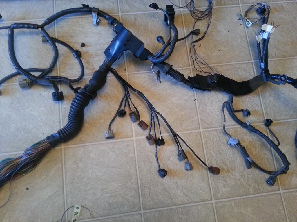
I kept the auto transmission plugs for the Red Mamba 2 harness .
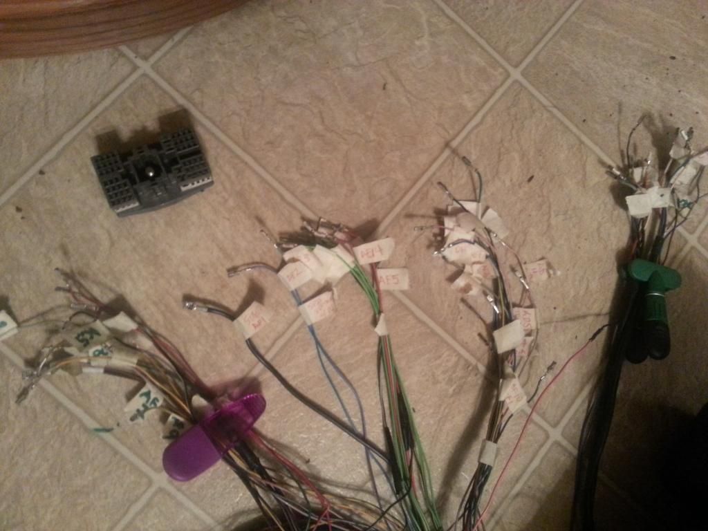
I have 12 extra wires plus a +Voltage and ground wires which I can use for different sensors in the future on this area of the harness.
The Big Aristo Gray Plug has zero pins and wires now as you can see it on the picture below. I have organized all wires like which one are for the Diagnostic port , which ones are for the auto transmissions , which are extra wires and so on . When I do the merging of the Aristo 2jzgte harness with the SC300 harness , I know exactly where the wires will go. Good Labeling is the secret !


I have 12 extra wires plus a +Voltage and ground wires which I can use for different sensors in the future on this area of the harness.

The Big Aristo Gray Plug has zero pins and wires now as you can see it on the picture below. I have organized all wires like which one are for the Diagnostic port , which ones are for the auto transmissions , which are extra wires and so on . When I do the merging of the Aristo 2jzgte harness with the SC300 harness , I know exactly where the wires will go. Good Labeling is the secret !

Last edited by gerrb; 01-30-14 at 04:54 PM.
01-15-14, 12:27 PM
#2124
Let us update our CHART
80 PIN ECU CONNECTOR
1 <--> Pin 1 of O/D Direct Clutch Speed Sensor CHECKED
2
3 <--> Pin 2 of A/T Rotation Sensor (Speed Sensor 2) CHECKED
7 <--> Pin 1 of the Crankshaft Position Sensor CHECKED
9 <--> Pin 8 of Transmission Solenoid CHECKED
10 <--> Pin 4 of Transmission Solenoid CHECKED
12 <--> Pin 5 of Transmission Solenoid CHECKED
13 <--> Pin 6 of Transmission Solenoid CHECKED
14 <--> Pin 7 of Transmission Solenoid CHECKED
20 <--> Pin 1 of the Injector No. 1 CHECKED
21 <--> Pin 2 of O/D Direct Clutch Speed Sensor CHECKED
23 <--> Pin 1 of A/T Rotation Speed Sensor (Speed Sensor 2) CHECKED
24 <--> Pin 2 of the A/T Fluid Temp Sensor CHECKED
27 <--> Pin 2 of the Crankshaft Position Sensor CHECKED
30
31 <--> Pin 1 of Transmission Solenoid CHECKED
38 <--> Pin 2 of the VSV3 CHECKED
39 <--> Pin 2 of the VSV2 CHECKED
40 <--> Pin 2 of the VSV1 CHECKED
41 <--> Pin 1 of the TPS <--> Pin 4 of the Sub-TPS CHECKED
42 <--> Pin 3 of the Sub-TPS CHECKED
43 <--> Pin 2 of the TPS CHECKED
44 <--> Pin 2 of the Water Temperature Sensor CHECKED
48 <--> Pin 3 of the O2 Sensor CHECKED
49 <--> Pin 1 of the Knock Sensor 1 CHECKED
50 <--> Pin 1 of the Knock Sensor 1 CHECKED
51
52 <--> Pin 7 of the 12 pin Igniter Connector CHECKED
53 <--> Pin 8 of the 12 pin igniter Connector CHECKED
54 <--> Pin 9 of the 12 pin igniter Connector CHECKED
55 <--> Pin 3 of the 12 pin igniter Connector CHECKED
56 <--> Pin 2 of the 12 pin Igniter Connector CHECKED
57 <--> Pin 1 of the 12 pin Igniter Connector CHECKED
58 <--> Pin 3 of the 4 pin Igniter Connector CHECKED
59
60 <--> Pin 2 of the VSVPMC CHECKED
63 <--> Pin 2 of the Sub-TPS CHECKED
64 <--> Pin 3 of the TPS CHECKED
65 <--> Pin 1 of the Water Temperature Sensor <--> Pin 4 of the TPS <--> Pin 1 of the Sub-TPS <--> Pin 1 of A/T Fluid Temp Sensor CHECKED
69 <--> Rear Intake Manifold Ground CHECKED
70
71 <--> Pin 1 of the O2 Sensor CHECKED
74 <--> Pin 2 of the VSVEVAP CHECKED
79 <--> Rear Intake Manifold Ground CHECKED
80 <--> Rear Intake Manifold Ground CHECKED
4 PIN IGNITER CONNECTOR
1 <--> Pin 12 of Plug F of Aristo plug <--> ( Pin 19 of the Data Link Connector <--> ( SC3 IK1-8 , SC4 IK1-8 , MK4 ))
2 <--> Pin 6 of Plug F of Aristo plug <--> Pin 1 of the Noise Filter <--> ( SC3 IJ1-7 , SC4 EB2-2 , MK4 IJ1-1 or IJ1-9 )
3 <--> Pin 58 of the 80 pin ECU connector CHECKED
4 <--> Ground Connector on the Front Side of Intake Manifold <--> Pin 2 of the Noise filter Connector CHECKED
12 PIN IGNITER CONNECTOR
1 <--> Pin 57 of the 80 pin ECU connector CHECKED
2 <--> Pin 56 of the 80 pin ECU connector CHECKED
3 <--> Pin 55 of the 80 pin ECU connector CHECKED
4 <--> Pin 2 of the Ignition Coil Connector 3 CHECKED
5 <--> Pin 2 of the Ignition Coil Connector 2 CHECKED
6 <--> Pin 2 of the Ignition Coil Connector 1 CHECKED
7 <--> Pin 52 of the 80 pin ECU connector CHECKED
8 <--> Pin 53 of the 80 pin ECU connector CHECKED
9 <--> Pin 54 of the 80 pin ECU connector CHECKED
10 <--> Pin 2 of the Ignition Coil Connector 4 CHECKED
11 <--> Pin 2 of the Ignition Coil Connector 5 CHECKED
12 <--> Pin 2 of the Ignition Coil Connector 6 CHECKED
AC COMPRESSOR PLUG
1 <--> Pin 1 of Plug C of the Aristo Plug (should go to (SC3 EB1-7 & II1-1 , SC4 ED1-8 then to EB1-7 & II1-1 , MK4 II1-26 ))
2 <--> Pin 2 of Plug C of the Aristo Plug (should go to (SC3 II1-4 , SC4 ED1-4 then to II1-4 , MK4 II1-20 ))
4 <--> Pin 5 of Plug C of the Aristo Plug (should go to (SC3 EB1-1 , SC4 ED2-1 then to EB1-1 , MK4 EA1-1 & II1-10 ))
A/T FLUID TEMP SENSOR
1 <--> Pin 65 of 80 pin ECU Connector CHECKED
2 <--> Pin 24 of 80 pin ECU Connector CHECKED
A/T ROTATION SPEED SENSOR (Speed Sensor 2)
1 <--> Pin 23 of 80 pin ECU Connector CHECKED
2 <--> Pin 3 of 80 pin ECU Connector CHECKED
A/T INDICATOR SWITCH
2 <--> Pin 9 of Plug E of the Big Aristo Plug (should go to Pin 9 of the 40 pin ECU Connector & to ( SC3 IK1-16 , SC4 IK1-16 , MK4 II1-17 ))
3 <--> Pin 10 of Plug E of the Big Aristo Plug (should go to Pin 10 of the 40 pin ECU Connector & to ( SC3 IK1-17 , SC4 IK1-17 , MK4 II1-27 ))
4 <--> Pin 14 of Plug E of the Big Aristo Plug (should go to ( SC3 IJ1-10 , SC4 IJ1-10 , MK4 II1-23 ))
5 <--> Pin 12 of Plug E of the Big Aristo Plug
6 <--> Pin 5 of Plug E of the Big Aristo Plug
7 <--> Pin 4 of Plug E of the Big Aristo Plug (should go to ( SC3 IK1-12 , SC4 IK1-12 , MK4 II1-7 ))
8 <--> Pin 13 of Plug E of the Big Aristo Plug (should go to Pin 7 of the 40 pin ECU Connector & to ( SC3 IK1-11 , SC4 IK1-11 , MK4 II1-36 ))
9 <--> Pin 11 of Plug E of the Big Aristo Plug (should go to ( SC3 IK1-14 , SC4 IK1-14 , MK4 II1-18 ))
10 <--> Pin 8 of Plug E of the Big Aristo Plug (should go to ( SC3 IK1-13 , SC4 IK1-13 , MK4 II1-1 ))
CRANKSHAFT POSITION SENSOR
1 <--> Pin 7 of the 80 pin ECU Connector CHECKED
2 <--> Pin 27 of the 80 pin ECU Connector CHECKED
DIAGNOSTIC PORT
1 (FP) <--> Pin 15 of Plug C of the Big Gray Aristo Plug (should go to (SC3 IJ1-1 , SC4 IJ1-1 , MK4 IJ1-8 ))
2 (W) <--> Pin 2 of Plug E of the Big Gray Aristo Plug (should go to Pin 6 of the 40 pin ECU Connector & to (SC3 IK2-9 , SC4 IK2-9 , MK4 II1-15 ))
3 (E1) <--> Pin 11 of Plug F of the Big Gray Aristo Plug (should go to Rear Intake Manifold Ground & to (SC3 Pin 69,79,80 of the 80 pin ECU Connector , SC4 Pin 69,79,80 of the 80 pin ECU Connector , MK4 IJ1-18 ))
4 (OX1)<--> Pin 48 of the 80 pin ECU Connector
5 (AB) <--> Pin 4 of Plug D of the Big Gray Aristo Plug
6 (OP1)<--> Pin 10 of Plug D of the Big Gray Aristo Plug
7 (CCo)<--> Pin 8 of Plug D of the Big Gray Aristo Plug
8 (TE1) <--> Pin 4 of Plug F of the Big Gray Aristo Plug(should go to Pin 20 of the 40 pin ECU Connector & to ( SC3 IK1-4 , SC4 IK1-4 , MK4 IJ1-5 ))
9 (TE2) <--> Pin 7 of Plug E of the Big Gray Aristo Plug (should go to Pin 19 of the 40 pin ECU Connector & to ( SC3 IK1-2 , SC4 IK1-2 , MK4 IJ1-17 ))
11 (TC)<--> Pin 6 of Plug E of the Big Gray Aristo Plug
12 (+B)<--> Pin 3 of Plug E of the Big Gray Aristo Plug (should go to (SC3 IJ1-12 & EB2-1 & Short-4 & Pin 2 of O2 Sensor , SC4 IJ1-12 & EB2-3 & Pin 2 of O2 Sensor , MK4 EA3-3 & Pin 31 of 40 pin ECU Connector ))
13 (VF1)<-->Pin 10 of Plug F of the Big Gray Aristo Plug (should go to Pin 29 of the 80 pin ECU Connector & to ( SC3 IK1-3 , SC4 IK1-3 , MK4 IJ1-13 ))
16 (TS)<--> Pin 5 of Plug F of the Big Gray Aristo Plug
18 (TEM)<--> Pin 5 of Plug D of the Big Gray Aristo Plug
19 (IG-) <--> Pin 1 of the 4 pin Igniter Connector
22 (WA) <--> PIn 7 of Plug D of the Big Gray Aristo Plug
23 (WB) <--> Pin 11 of Plug D of the Big Gray Aristo Plug
GROUND - Front Intake Manifold
1 <--> Pin 2 of Noise Filter <--> Pin 4 of the 4 pin ECU CONNECTOR CHECKED
GROUND - Rear Intake Manifold
1 <--> Pin 69 <---> Pin 79 <--> Pin 80 of the 80 pin ECU Connector CHECKED
IGNITION COIL 1
1 <--> Pin 1 of the Noise Filter <--> Pin 2 of the 4 pin Igniter Connector <--> Pin 1 of Ignition Coil 2,3,4,5,6 <-->( SC3 IJ1-7 , SC4 EB2-2 , MK4 IJ1-1 or IJ1-9 )
2 <--> Pin 6 of the 12 Pin Igniter Connector CHECKED
IGNITION COIL 2
1 <--> Pin 1 of the Noise Filter <--> Pin 2 of the 4 pin Igniter Connector <--> Pin 1 of Ignition Coil 1,3,4,5,6 <-->( SC3 IJ1-7 , SC4 EB2-2 , MK4 IJ1-1 or IJ1-9 )
2 <--> Pin 5 of the 12 Pin Igniter Connector CHECKED
IGNITION COIL 3
1 <--> Pin 1 of the Noise Filter <--> Pin 2 of the 4 pin Igniter Connector <--> Pin 1 of Ignition Coil 1,2,4,5,6 <-->( SC3 IJ1-7 , SC4 EB2-2 , MK4 IJ1-1 or IJ1-9 )
2 <--> Pin 4 of the 12 Pin Igniter Connector CHECKED
IGNITION COIL 4
1 <--> Pin 1 of the Noise Filter <--> Pin 2 of the 4 pin Igniter Connector <--> Pin 1 of Ignition Coil 1,2,3,5,6 <-->( SC3 IJ1-7 , SC4 EB2-2 , MK4 IJ1-1 or IJ1-9 )
2 <--> Pin 10 of the 12 Pin Igniter Connector CHECKED
IGNITION COIL 5
1 <--> Pin 1 of the Noise Filter <--> Pin 2 of the 4 pin Igniter Connector <--> Pin 1 of Ignition Coil 1,2,3,4,6 <-->( SC3 IJ1-7 , SC4 EB2-2 , MK4 IJ1-1 or IJ1-9 )
2 <--> Pin 11 of the 12 Pin Igniter Connector CHECKED
IGNITION COIL 6
1 <--> Pin 1 of the Noise Filter <--> Pin 2 of the 4 pin Igniter Connector <--> Pin 1 of Ignition Coil 1,2,3,4,5 <-->( SC3 IJ1-7 , SC4 EB2-2 , MK4 IJ1-1 or IJ1-9 )
2 <--> Pin 12 of the 12 Pin Igniter Connector CHECKED
INJECTOR NO. 1
1 <--> Pin 20 of the 80 pin ECU Connector
2 <--> (should go to (SC3 IJ1-7 or IJ1-3 & short 3 & short 5 , SC40 EB2-2 , MK4 IJ1-9))
KNOCK SENSOR 1
1 <--> Pin 50 of the 80 pin ECU Connector CHECKED
KNOCK SENSOR 2
1 <--> Pin 49 of the 80 pin ECU Connector CHECKED
NOISE FILTER
1 <--> Pin 2 of the 4 pin Igniter Connector <--> ( SC3 IJ1-7, SC4 EB2-2 , MK4 IJ1-1 or IJ1-9 )
2 <--> Ground Connector on the Front Side of Intake Manifold <--> Pin 4 of the 4 pin Igniter Connector CHECKED
O/D DIRECT CLUTCH SPEED SENSOR (O/D)
1 <--> Pin 1 of 80 pin ECU Connector CHECKED
2 <--> Pin 21 of 80 pin ECU Connector CHECKED
OIL LEVEL SENSOR PLUG
1 <--> Pin 1 of Plug D of Big Gray Aristo Plug (should go to (SC3 IK2-10 , SC4 IK2-10 , MK4 II1-33 ))
2 <--> Pin 7 of Plug F of Big Gray Aristo Plug(should go to ( SC3 / SC4 / MK4 Rear Intake Manifold Ground for all ))
OIL PRESSURE PLUG
1 <--> Pin 8 of Plug F of the Aristo Plug (should go to ( SC3 IK1-20 , SC4 IK1-20 , MK4 II1-25 ))
STARTER
1 <--> Pin 1 of Plug F of Big Gray Aristo Plug (should go to (SC3 EB2-1 , SC4 ED2-2 then EB2-1 , MK4 EA3-1 ))
THROTTLE POSITION SENSOR
1 <--> Pin 41 of the 80 pin ECU Connector CHECKED
2 <--> Pin 43 of the 80 pin ECU Connector CHECKED
3 <--> Pin 64 of the 80 pin ECU Connector CHECKED
4 <--> Pin 65 of the 80 pin ECU Connector CHECKED
TRANSMISSION SOLENOID (ECT Solenoid)
1 <--> Pin 31 of 80 pin ECU Connector
2 <--> Pin 3 of Plug E of the Big Aristo Plug (should go to (Pin 12 of the Data Link Connector & to ( SC3 IJ1-12 & EB2-1 & Short-4 , SC4 IJ1-12 & EB2-3 , MK4 EA3-3 )))
3 <--> Pin 3 of Plug E of the Big Aristo Plug (should go to (Pin 12 of the Data Link Connector & to ( SC3 IJ1-12 & EB2-1 & Short-4 , SC4 IJ1-12 & EB2-3 , MK4 EA3-3 )))
4 <--> Pin 10 of 80 pin ECU Connector
5 <--> Pin 12 of 80 pin ECU Connector
6 <--> Pin 13 of 80 pin ECU Connector
7 <--> Pin 14 of 80 pin ECU Connector
8 <--> Pin 9 of 80 pin ECU Connector
WATER TEMPERATURE SENSOR
1 <--> Pin 65 of the 80 pin ECU Connector CHECKED
2 <--> Pin 44 of the 80 pin ECU Connector CHECKED
WATER TEMPERATURE GAUGE SENDER
1 <--> Pin 9 of Plug F of the Big Gray Aristo Plug (should go to SC3 IK1-9 , SC4 IK1-9 & Short-3 , MK4 II1-19 )
The following plugs are necessary only if you are going stock 2jzgte setup
OXYGEN SENSOR (O2)
1 <--> Pin 71 of the 80 pin ECU Connector CHECKED
2 <--> Pin 3 of Plug E of Aristo Plug <-> (Pin 12 of the Data Link Connector <--> ( SC3 IJ1-12 & EB2-1 & Short-4 , SC4 IJ1-12 & EB2-3 , MK4 EA3-3 ))
3 <--> Pin 48 of the 80 pin ECU Connector CHECKED
VSV1 ( Air Intake Control Valve )
1 <--> Pin 2 of the O2 Sensor <--> Pin 1 of the VSV3 <-> (Pin 12 of the Data Link Connector <--> ( SC3 IJ1-12 & EB2-1 & Short-4 , SC4 IJ1-12 & EB2-3 , MK4 EA3-3 ))
2 <--> Pin 40 of the 80 pin ECU Connector CHECKED
VSV2 ( Exhaust Control Valve )
1 <--> Pin 1 of VSV1 , VSV3 , VSVPMC <--> Pin 2 of the O2 Sensor <--> Pin 1 of the VSV3 <-> (Pin 12 of the Data Link Connector <--> ( SC3 IJ1-12 & EB2-1 & Short-4 , SC4 IJ1-12 & EB2-3 , MK4 EA3-3 ))
2 <--> Pin 39 of the 80 pin ECU Connector CHECKED
VSV3( Exhaust Bypass Valve )
1 <--> Pin 2 of the O2 Sensor <-->Pin 1 of the VSV1 <-> (Pin 12 of the Data Link Connector <--> ( SC3 IJ1-12 & EB2-1 & Short-4 , SC4 IJ1-12 & EB2-3 , MK4 EA3-3 ))
2 <--> Pin 38 of the 80 pin ECU Connector CHECKED
VSVEVAP ( Canister Purge )
1 <--> Pin 1 of VSV1 , VSV2 , VSV3 , VSVPMC <--> (Pin 12 of the Data Link Connector <--> ( SC3 IJ1-12 & EB2-1 & Short-4 , SC4 IJ1-12 & EB2-3 , MK4 EA3-3 ))
2 <--> Pin 74 of the 80 pin ECU Connector
VSVPMC ( Waste Gate Valve )
1 <--> Pin 1 of VSV1 , VSV2 , VSV3 <--> Pin 2 of the O2 Sensor <--> Pin 1 of the VSV3 <-> (Pin 12 of the Data Link Connector <--> ( SC3 IJ1-12 & EB2-1 & Short-4 , SC4 IJ1-12 & EB2-3 , MK4 EA3-3 ))
2 <--> Pin 60 of the 80 pin ECU Connector CHECKED
The following plugs maybe kept or deleted depending on your seup
2) Sub-Throttle Position Sensor
1 <--> Pin 65 of the 80 pin ECU Connector CHECKED
2 <--> Pin 63 of the 80 pin ECU Connector CHECKED
3 <--> Pin 42 of the 80 pin ECU Connector CHECKED
4 <--> Pin 41 of the 80 pin ECU Connector CHECKED
The following plugs are usually deleted
Throttle Motor Valve
1 <--> Pin 8 of Plug C of Big Gray Aristo Plug
2 <--> Pin 11 of Plug C of Big Gray Aristo Plug
3 <--> Pin 7 of Plug C of Big Gray Aristo Plug
4 <--> Pin 4 of Plug C of Big Gray Aristo Plug
5 <--> Pin 6 of Plug C of Big Gray Aristo Plug
6 <--> Pin 3 of Plug C of Big Gray Aristo Plug
The following plug definitely will be deleted but its wires go to different body plugs or 40 pin ECU Connector or can be used for future needs
BIG GRAY ARISTO PLUG
PLUG C
1 <--> (SC3 EB1-7 & II1-1 , SC4 ED1-8 then to EB1-7 & II1-1 , MK4 II1-26 ))
2 <-->(should go to (SC3 II1-4 , SC4 ED1-4 then to II1-4 , MK4 II1-20 ))
3 <--> Extra Wire for future use CHECKED
4 <--> Extra Wire for future use CHECKED
5 <--> (should go to (SC3 EB1-1 , SC4 ED2-1 then to EB1-1 , MK4 EA1-1 & II1-10 ))
6 <--> Extra Wire for future use CHECKED
7 <--> Extra Wire for future use CHECKED
8 <--> Extra Wire for future use CHECKED
11 <--> Extra Wire for future use CHECKED
13 <--> Extra Wire for future use CHECKED
15 <--> Pin 1 (FP) of Diagnostic Port goes (should go to (SC3 IJ1-1 , SC4 IJ1-1 , MK4 IJ1-8 ))
PLUG D
1 <--> (should go to (SC3 IK2-10 , SC4 IK2-10 , MK4 II1-33 ))
4 <--> Pin 5 (AB) of Diagnostic Port
5 <--> Pin 18 (TEM) of Diagnostic Port
6 <--> Pin 63 of the 80 pin ECU Connector (Is still needed ????? remains to be seen during the merge process)
7 <--> Pin 22 (WA) of Diagnostic Port
8 <--> Pin 7 (CCo) of Diagnotic Port
9 <--> Extra Wire for future use CHECKED
10<-->Pin 6 (OP1) of Diagnostic Port
11<-->Pin 23 (WB) of Diagnostic Port
PLUG E
2 <--> Pin 2 (W) of Diagnostic Port (should go to Pin 6 of the 40 pin ECU Connector & to (SC3 IK2-9 , SC4 IK2-9 , MK4 II1-15 ))
3 <--> Pin 2 of Oxygen Sensor <--> Pin 2 & Pin 3 of Transmission Solenoid <--> (Pin 12 of the Data Link Connector <--> ( SC3 IJ1-12 & EB2-1 & Short-4 , SC4 IJ1-12 & EB2-3 , MK4 EA3-3 ))
4 <--> Pin 12 (+B) of Diagnostic Port <--> Pin 7 of A/T Indicator Switch (should go to (SC3 IJ1-12 & EB2-1 & Short-4 & Pin 2 of O2 Sensor & IK1-12 , SC4 IJ1-12 & EB2-3 & Pin 2 of O2 Sensor & IK1-12 , MK4 EA3-3 & Pin 31 of 40 pin ECU Connector & II1-7 ))
5 <--> Pin 6 of A/T Indicator Switch
6 <--> Pin 11 (TC) of Diagnostic Port
7 <--> Pin 9 (TE2) of Diagnostic Port (should go to Pin 19 of the 40 pin ECU Connector & to ( SC3 IK1-2 , SC4 IK1-2 , MK4 IJ1-17 ))
8 <--> Pin 10 of A/T Indicator Switch (should go to ( SC3 IK1-13 , SC4 IK1-13 , MK4 II1-1 ))
9 <--> Pin 2 of A/T Indicator Switch (should go to Pin 9 of the 40 pin ECU Connector & to ( SC3 IK1-16 , SC4 IK1-16 , MK4 II1-17 ))
10 <--> Pin 3 of A/T Indicator Switch (should go to Pin 10 of the 40 pin ECU Connector & to ( SC3 IK1-17 , SC4 IK1-17 , MK4 II1-27 ))
11 <--> Pin 9 of A/T Indicator Switch (should go to ( SC3 IK1-14 , SC4 IK1-14 , MK4 II1-18 ))
12 <--> Pin 5 of A/T Indicator Switch
13 <--> Pin 8 of A/T Indicator Switch (should go to Pin 7 of the 40 pin ECU Connector & to ( SC3 IK1-11 , SC4 IK1-11 , MK4 II1-36 ))
14 <--> Pin 4 of A/T Indicator Switch (should go to ( SC3 IJ1-10 , SC4 IJ1-10 , MK4 II1-23 ))
PLUG F
4 <--> Pin 8 (TE1) of Diagnostic Port ((should go to Pin 20 of the 40 pin ECU Connector & to ( SC3 IK1-4 , SC4 IK1-4 , MK4 IJ1-5 ))
5 <--> Pin 16 (TS) of Diagnostic Port
6 <--> Pin 1 of the Noise Filter <--> ( SC3 IJ1-7 , SC4 EB2-2 , MK4 IJ1-1 or IJ1-9 )
7 <--> (should go to ( SC3 / SC4 / MK4 Rear Intake Manifold Ground for all ))
8 <--> (should go to ( SC3 IK1-20 , SC4 IK1-20 , MK4 II1-25 ))
9 <--> Pin 1 of the Water Temperature Gauge Sender <--> ( SC3 IK1-9 , SC4 IK1-9 & Short-3 , MK4 II1-19 )
10<--> Pin 13 (VF1) of Diagnostic Port (should go to Pin 29 of the 80 pin ECU Connector & to ( SC3 IK1-3 , SC4 IK1-3 , MK4 IJ1-13 ))
11<--> Pin 3 (E1) of Diagnostic Port (should go to Rear Intake Manifold Ground & to (SC3 Pin 69,79,80 of the 80 pin ECU Connector , SC4 Pin 69,79,80 of the 80 pin ECU Connector , MK4 IJ1-18 ))
12 <--> ( Pin 19 of the Data Link Connector & to ( SC3 IK1-8 , SC4 IK1-8 , MK4 ))
Last edited by gerrb; 01-31-14 at 11:14 AM.
01-16-14, 04:01 AM
#2125
DIAGRAMS TO VERIFY PIN NUMBERING & WHERE THE WIRE GOES
*** O/D Direct Clutch Speed Sensor (O/D) & A/T Rotation Sensor (Speed Sensor 2) ***
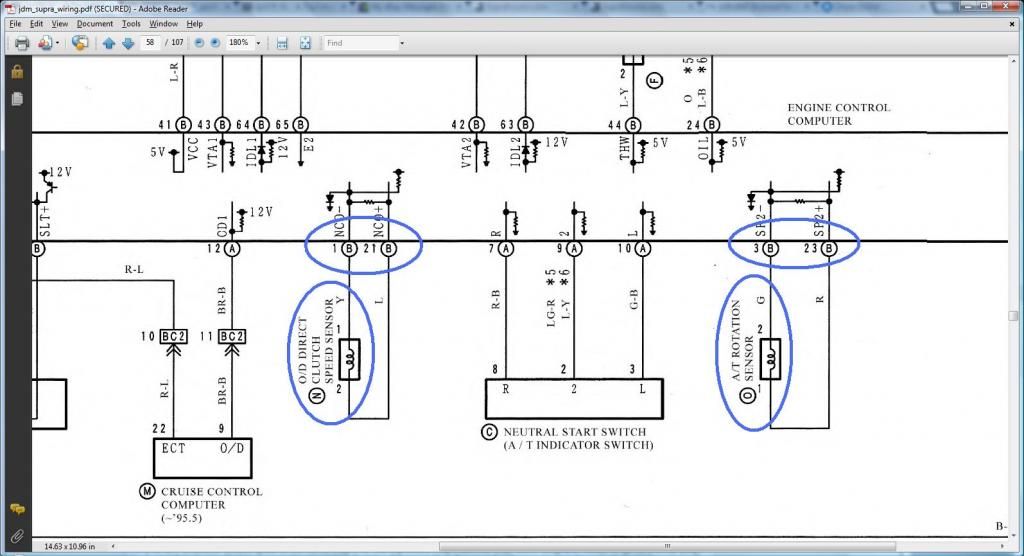
*** A/T Fluid Temp Sensor ***
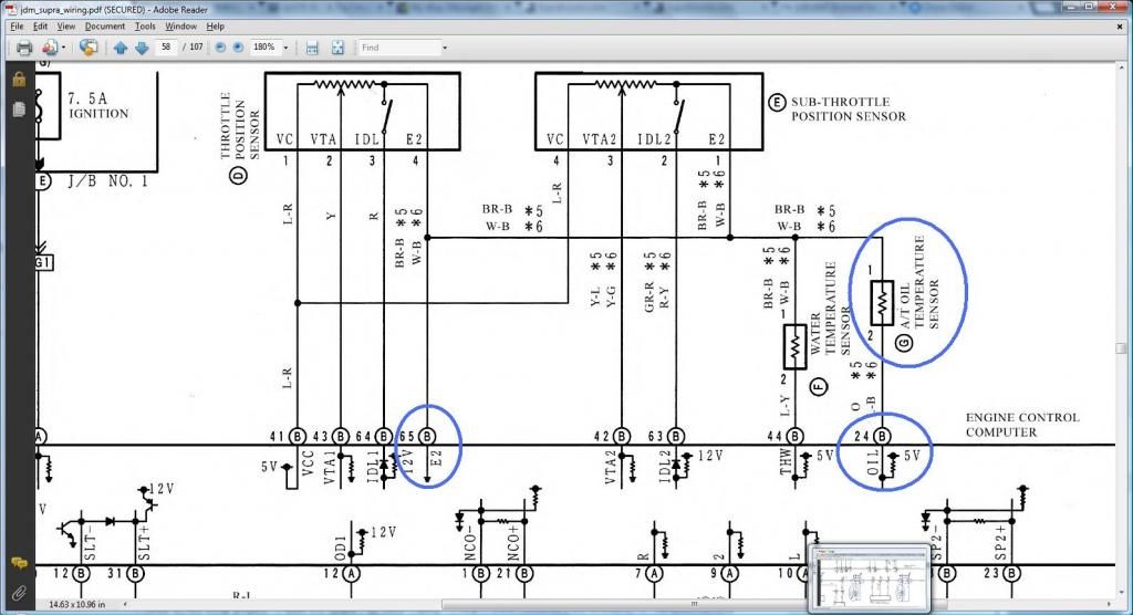
*** Transmission Solenoid (ECT Solenoid) ***
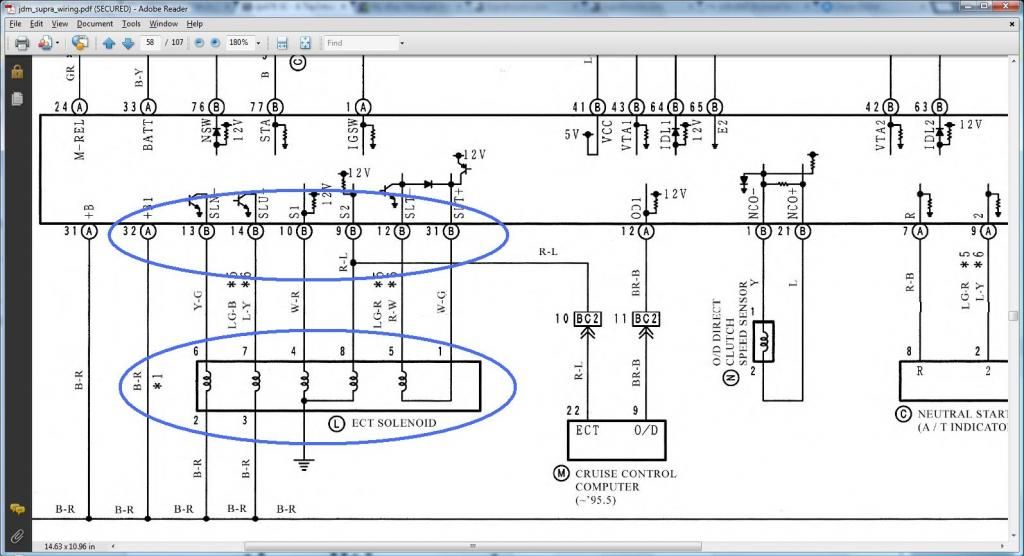
*** O/D Direct Clutch Speed Sensor (O/D) & A/T Rotation Sensor (Speed Sensor 2) ***

*** A/T Fluid Temp Sensor ***

*** Transmission Solenoid (ECT Solenoid) ***

Last edited by gerrb; 01-31-14 at 08:52 AM.
01-16-14, 12:02 PM
#2126
Q) Since those body plugs for SC300 and SC400 are basically the same, can i use one from an SC400 even if I have an SC300 and vice versa ?
YES .. provided you make sure they are pinned properly. SC300 wiring is not exactly the same as that of the SC400 wiring . Then you need to take in consideration of the year model too.. there are differences even if let's say they are the same SC300.
I have shown in the previous posts what the plug and pin a wire should go in an SC300 , SC400 and a MKIV. That should help.
Last edited by gerrb; 01-30-14 at 06:09 AM.
01-16-14, 01:55 PM
#2127
DIAGRAMS TO VERIFY WHERE A WIRE SHOULD GO IN A SC300, SC400, MKIV
*** Transmission Solenoid (ECT Solenoid) ***
Pin 2 of Transmission Solenoid (should go to (Pin 12 of the Data Link Connector & to ( SC3 IJ1-12 & EB2-1 & Short-4 , SC4 IJ1-12 & EB2-3 , MK4 EA3-3 )))
Pin 3 of Transmission Solenoid (should go to (Pin 12 of the Data Link Connector & to ( SC3 IJ1-12 & EB2-1 & Short-4 , SC4 IJ1-12 & EB2-3 , MK4 EA3-3 )))
Read this diagram being on the right of the next diagram so you see continuous
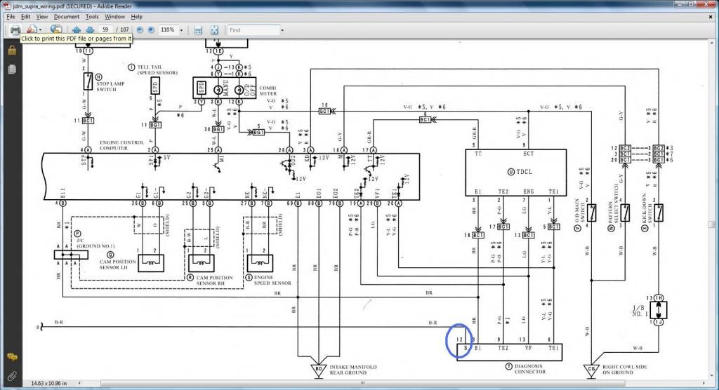
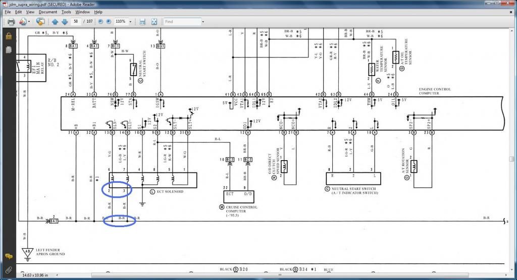
*** A/T Indicator Switch ***
Pin 2 of A/T Indicator Switch (should go to Pin 9 of the 40 pin ECU Connector & to ( SC3 IK1-16 , SC4 IK1-16 , MK4 II1-17 ))
Pin 3 of A/T Indicator Switch (should go to Pin 10 of the 40 pin ECU Connector & to ( SC3 IK1-17 , SC4 IK1-17 , MK4 II1-27 ))
Pin 4 of A/T Indicator Switch (should go to ( SC3 IJ1-10 , SC4 IJ1-10 , MK4 II1-23 ))
Pin 7 of A/T Indicator Switch (should go to ( SC3 IK1-12 , SC4 IK1-12 , MK4 II1-7 ))
Pin 8 of A/T Indicator Switch (should go to Pin 7 of the 40 pin ECU Connector & to( SC3 IK1-11 , SC4 IK1-11 , MK4 II1-36 ))
Pin 9 of A/T Indicator Switch (should go to ( SC3 IK1-14 , SC4 IK1-14 , MK4 II1-18 ))
Pin 10 of A/T Indicator Switch (should go to ( SC3 IK1-13 , SC4 IK1-13 , MK4 II1-1 ))
I want you to pay attention on the next diagram for the 2jzgte Auto Transmission indicator switch numbering. I have encircled those numbers. This is what we are going to use. When I post the indicator switch of the SC300 / SC400 later , they have a different numbering but don't worry about it. It's this numbering on the next diagram that matters.
Pin 7 - Park
Pin 8 - Reverse
Pin 10- Neutral
Pin 9 - Drive
Pin 2 - 2nd Gear
Pin 3 - Low / 1st Gear
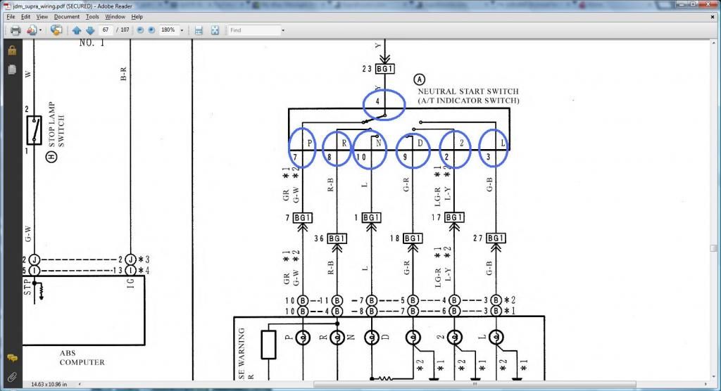
TAKE NOTE OF THE PIN NUMBERS
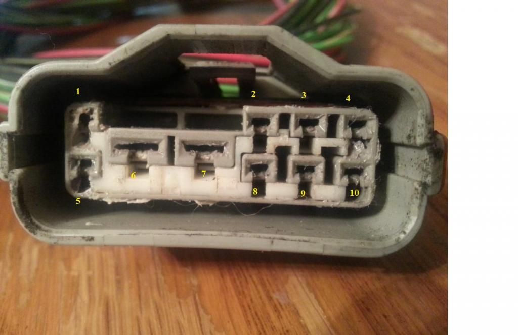
SC300 Read this diagram being on the right of the next diagram so you see continuous flow of current
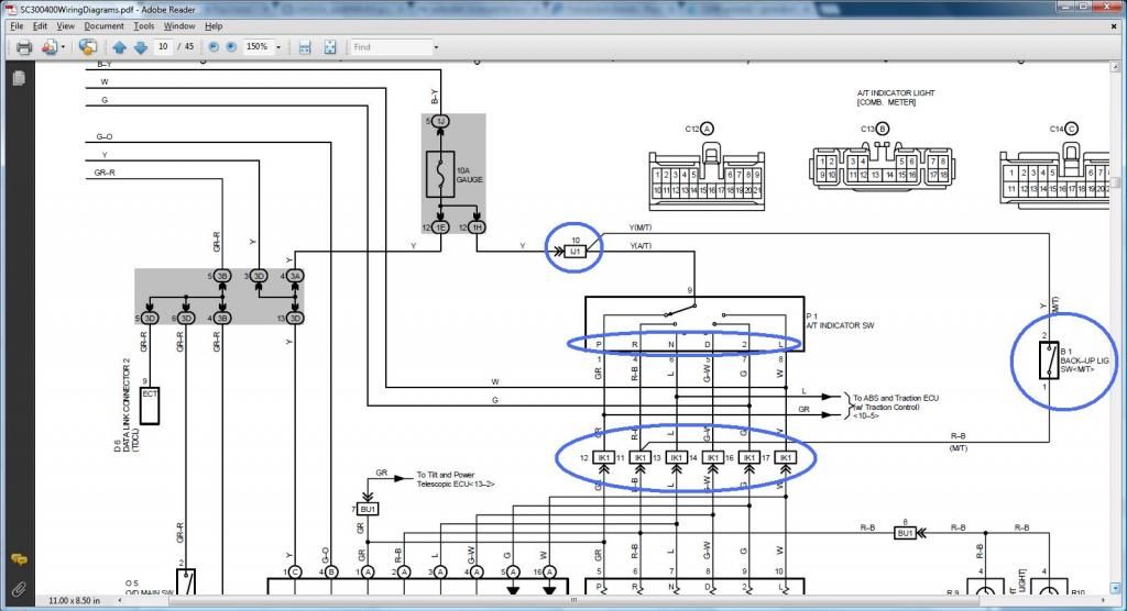
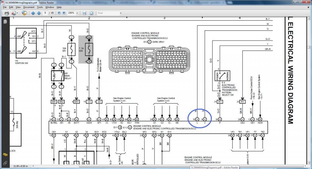
SC400 Read this diagram being on the right of the next diagram so you see continuous flow of current
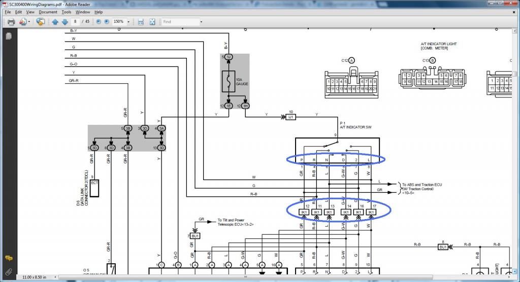
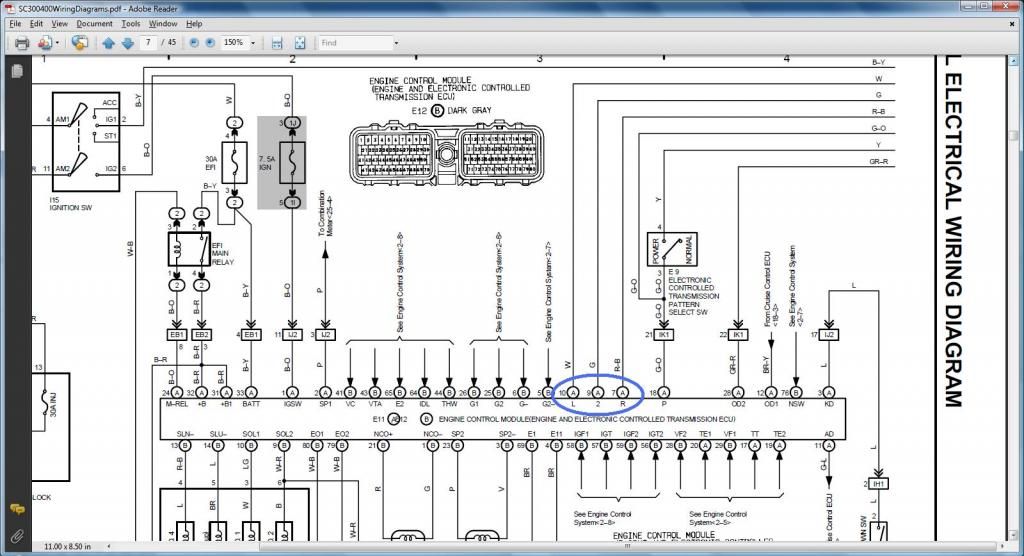
MKIV Read this diagram being on the right of the next diagram so you see continuous flow of current
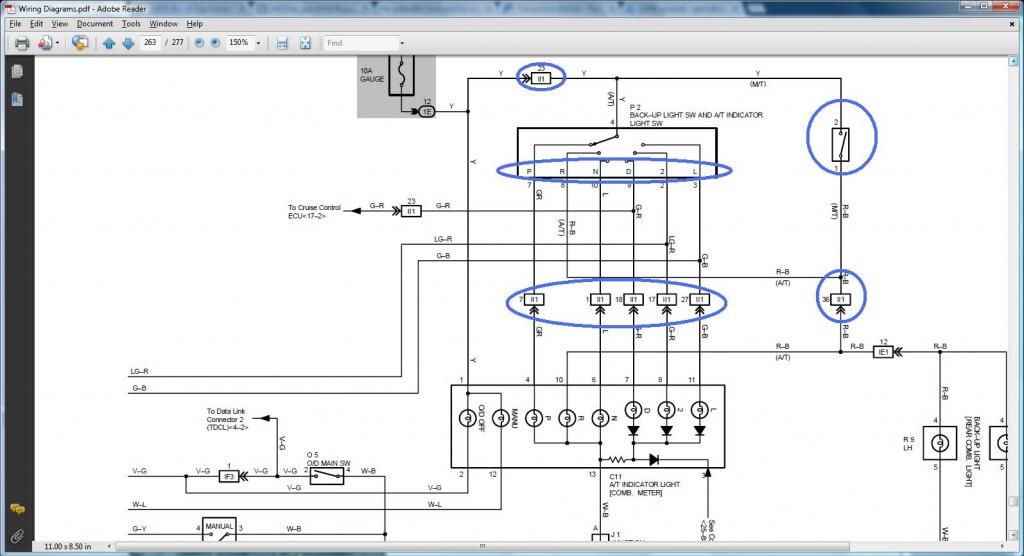
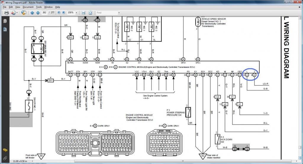


Last edited by gerrb; 01-31-14 at 08:45 AM.
01-16-14, 01:59 PM
#2128
SORRY GUYS ... pictures will be back up on the 18th or 19th after my account resets . That is what happens when you are poor and all you can have is a free photobucket acccount  .
.
Have exceeded data transfers due to the amount of views on this thread and you know how picture heavy the thread is.
.Have exceeded data transfers due to the amount of views on this thread and you know how picture heavy the thread is.
Last edited by gerrb; 01-17-14 at 05:55 AM.
01-17-14, 05:10 AM
#2129
Let us now deal with the connectors on this area .. quite a bit as you see.
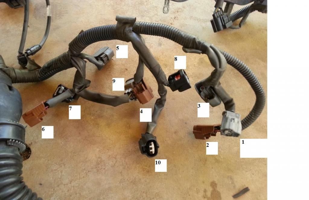
The INFO you will need to do THE DRILL
1) Intake Air Temp Sensor (IAT)
Pin 2 of IAT goes to pin 45 of 80 pin ECU Connector
Pin 1 of IAT goes to pin 65 of 80 pin ECU Connector
2) Injector #2
Piin 1 of Injector #2 goes to pin 19 of 80 pin ECU Connector
Pin 2 of Injector #2 (should go to (SC3 IJ1-7 or IJ1-3 & short 3 & short 5 , SC40 EB2-2 , MK4 IJ1-9))
3) Injector #3
Pin 1 of Injector #3 goes to pin 18 of 80 pin ECU Connector
Pin 2 of Injector #3 (should go to (SC3 IJ1-7 or IJ1-3 & short 3 & short 5 , SC40 EB2-2 , MK4 IJ1-9))
4) Injector #4
Pin 1 of Injector #4 goes to pin 17 of 80 pin ECU Connector
Pin 2 of Injector #4 (should go to (SC3 IJ1-7 or IJ1-3 & short 3 & short 5 , SC40 EB2-2 , MK4 IJ1-9))
5) Injector #5
Pin 1 of Injector #5 goes to pin 16 of 80 pin ECU Connector
Pin 2 of Injector #5 (should go to (SC3 IJ1-7 or IJ1-3 & short 3 & short 5 , SC40 EB2-2 , MK4 IJ1-9))
6) Injector #6
Pin 1 of Injector #6 goes to pin 15 of 80 pin ECU Connector
Pin 2 of Injector #6 (should go to (SC3 IJ1-7 or IJ1-3 & short 3 & short 5 , SC40 EB2-2 , MK4 IJ1-9))
7) Cam Sensor #2
Pin 1 of Cam Sensor #2 goes to pin 25 of 80 pin ECU Connector
Pin 2 of Cam Sensor #2 goes to pin 5 of 80 pin ECU Connector
8) Cam Sensor #1
Pin 1 of Cam Sensor #1 goes to pin 26 of 80 pin ECU Connector
Pin 2 of Cam Sensor #1 goes to pin 6 of 80 pin ECU Connector
9) IACV
Pin 1 of IACV goes to pin 34 of 80 pin ECU Connector
Pin 2 of IACV goes to pin 31 of 40 pin ECU Connector
Pin 3 of IACV goes to pin 32 of 80 pin ECU Connector
Pin 4 of IACV goes to pin 35 of 80 pin ECU Connector
Pin 5 of IACV goes to pin 31 of 40 pin ECU Connector
Pin 6 of IACV goes to pin 33 of 80 pin ECU Connector
10)Manifold Air Pressure Sensor (MAP / Turbo Pressure Sensor / Vacuum Sensor )
Pin 1 of Map Sensor goes to Pin 65 of 80 pin ECU Connector
Pin 2 of MAP Sensor goes to pin 62 of 80 pin ECU Connector
Pin 3 of MAP Sesor goes to pin 41 of 80 pin ECU Connector
NOTE : You be careful on the IACV . Take note of Pin 2 and 5 of the IACV . They go to the 40 pin ECU Connector . We will eventually have to start populating the 40 pin ECU connector.
Guys , time to do THE DRILL .
Last edited by gerrb; 01-31-14 at 11:14 AM.
01-17-14, 05:53 AM
#2130
Q) Wouldn't it be better to wrap those corrugated flexible hose wrap also with electrical tape ?
Yes you can . It is personal preference and true , wrapping that corrugated flexible hose with electrical tape will also provide extra protection on your harness.
At this point , there will still be wires added during the merging process. You don't want to finalize your wrapping then undo due to the fact you need to add wires.
On my end , I don't wrap all corrugated flexible hose with electrical tape. It depends which one. When you wrap the whole corrugated flexible hose with electrical tape , it becomes kinda stiff ... looses flexibility. That's one reason I wrapped the wires of each plug before I wrap them with the corrugated flexible hose.
Last edited by gerrb; 01-31-14 at 11:13 AM.