2jzGTE SCs - The Siblings of my Supra MKIV Toys


 01-18-14, 07:17 AM
#2133
Let us update our CHART
80 PIN ECU CONNECTOR
1 <--> Pin 1 of O/D Direct Clutch Speed Sensor CHECKED
2
3 <--> Pin 2 of A/T Rotation Sensor (Speed Sensor 2) CHECKED
5 <--> Pin 2 of the Camshaft Sensor # 2 CHECKED
6 <--> Pin 2 of the Camshaft Sensor #1 CHECKED
7 <--> Pin 1 of the Crankshaft Position Sensor CHECKED
9 <--> Pin 8 of Transmission Solenoid CHECKED
10 <--> Pin 4 of Transmission Solenoid CHECKED
12 <--> Pin 5 of Transmission Solenoid CHECKED
13 <--> Pin 6 of Transmission Solenoid CHECKED
14 <--> Pin 7 of Transmission Solenoid CHECKED
15 <--> Pin 1 of the Injector No. 6 CHECKED
16 <--> Pin 1 of the Injector No. 5 CHECKED
17 <--> Pin 1 of the Injector No. 4 CHECKED
18 <--> Pin 1 of the Injector No. 3 CHECKED
19 <--> Pin 1 of the Injector No. 2 CHECKED
20 <--> Pin 1 of the Injector No. 1 CHECKED
21 <--> Pin 2 of O/D Direct Clutch Speed Sensor CHECKED
23 <--> Pin 1 of A/T Rotation Speed Sensor (Speed Sensor 2) CHECKED
24 <--> Pin 2 of the A/T Fluid Temp Sensor CHECKED
25 <--> Pin 1 of the Camshaft Sensor #2 CHECKED
26 <--> Pin 1 of the Camshaft Sensor #1 CHECKED
27 <--> Pin 2 of the Crankshaft Position Sensor CHECKED
30
31 <--> Pin 1 of Transmission Solenoid CHECKED
32 <--> Pin 3 of IACV CHECKED
33 <--> Pin 6 of IACV CHECKED
34 <--> Pin 1 of IACV CHECKED
35 <--> Pin 4 of IACV CHECKED
38 <--> Pin 2 of the VSV3 CHECKED
39 <--> Pin 2 of the VSV2 CHECKED
40 <--> Pin 2 of the VSV1 CHECKED
41 <--> Pin 1 of the TPS <--> Pin 4 of the Sub-TPS <--> Pin 3 of MAP CHECKED
42 <--> Pin 3 of the Sub-TPS CHECKED
43 <--> Pin 2 of the TPS CHECKED
44 <--> Pin 2 of the Water Temperature Sensor CHECKED
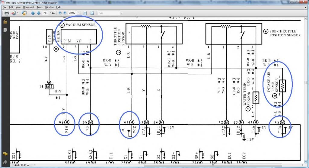
45 <--> Pin 2 of the Intake Air Temp Sensor CHECKED
48 <--> Pin 3 of the O2 Sensor CHECKED
49 <--> Pin 1 of the Knock Sensor 1 CHECKED
50 <--> Pin 1 of the Knock Sensor 1 CHECKED
51
52 <--> Pin 7 of the 12 pin Igniter Connector CHECKED
53 <--> Pin 8 of the 12 pin igniter Connector CHECKED
54 <--> Pin 9 of the 12 pin igniter Connector CHECKED
55 <--> Pin 3 of the 12 pin igniter Connector CHECKED
56 <--> Pin 2 of the 12 pin Igniter Connector CHECKED
57 <--> Pin 1 of the 12 pin Igniter Connector CHECKED
58 <--> Pin 3 of the 4 pin Igniter Connector CHECKED
59
60 <--> Pin 2 of the VSVPMC CHECKED
62 <--> Pin 2 of MAP CHECKED
63 <--> Pin 2 of the Sub-TPS CHECKED
64 <--> Pin 3 of the TPS CHECKED
65 <--> Pin 1 of the Water Temperature Sensor <--> Pin 4 of the TPS <--> Pin 1 of the Sub-TPS <--> Pin 1 of A/T Fluid Temp Sensor <--> Pin 1 of IAT <--> Pin 1 of MAP CHECKED
69 <--> Rear Intake Manifold Ground CHECKED
70
71 <--> Pin 1 of the O2 Sensor CHECKED
74 <--> Pin 2 of the VSVEVAP CHECKED
79 <--> Rear Intake Manifold Ground CHECKED
80 <--> Rear Intake Manifold Ground CHECKED
4 PIN IGNITER CONNECTOR
1 <--> Pin 12 of Plug F of Aristo plug <--> ( Pin 19 of the Data Link Connector <--> ( SC3 IK1-8 , SC4 IK1-8 , MK4 ))
2 <--> Pin 6 of Plug F of Aristo plug <--> Pin 1 of the Noise Filter <--> ( SC3 IJ1-7 , SC4 EB2-2 , MK4 IJ1-1 or IJ1-9 )
3 <--> Pin 58 of the 80 pin ECU connector CHECKED
4 <--> Ground Connector on the Front Side of Intake Manifold <--> Pin 2 of the Noise filter Connector CHECKED
12 PIN IGNITER CONNECTOR
1 <--> Pin 57 of the 80 pin ECU connector CHECKED
2 <--> Pin 56 of the 80 pin ECU connector CHECKED
3 <--> Pin 55 of the 80 pin ECU connector CHECKED
4 <--> Pin 2 of the Ignition Coil Connector 3 CHECKED
5 <--> Pin 2 of the Ignition Coil Connector 2 CHECKED
6 <--> Pin 2 of the Ignition Coil Connector 1 CHECKED
7 <--> Pin 52 of the 80 pin ECU connector CHECKED
8 <--> Pin 53 of the 80 pin ECU connector CHECKED
9 <--> Pin 54 of the 80 pin ECU connector CHECKED
10 <--> Pin 2 of the Ignition Coil Connector 4 CHECKED
11 <--> Pin 2 of the Ignition Coil Connector 5 CHECKED
12 <--> Pin 2 of the Ignition Coil Connector 6 CHECKED
AC COMPRESSOR PLUG
1 <--> Pin 1 of Plug C of the Aristo Plug (should go to (SC3 EB1-7 & II1-1 , SC4 ED1-8 then to EB1-7 & II1-1 , MK4 II1-26 ))
2 <--> Pin 2 of Plug C of the Aristo Plug (should go to (SC3 II1-4 , SC4 ED1-4 then to II1-4 , MK4 II1-20 ))
4 <--> Pin 5 of Plug C of the Aristo Plug (should go to (SC3 EB1-1 , SC4 ED2-1 then to EB1-1 , MK4 EA1-1 & II1-10 ))
A/T FLUID TEMP SENSOR
1 <--> Pin 65 of 80 pin ECU Connector CHECKED
2 <--> Pin 24 of 80 pin ECU Connector CHECKED
A/T ROTATION SPEED SENSOR (Speed Sensor 2)
1 <--> Pin 23 of 80 pin ECU Connector CHECKED
2 <--> Pin 3 of 80 pin ECU Connector CHECKED
A/T INDICATOR SWITCH
2 <--> Pin 9 of Plug E of the Big Aristo Plug (should go to Pin 9 of the 40 pin ECU Connector & to ( SC3 IK1-16 , SC4 IK1-16 , MK4 II1-17 ))
3 <--> Pin 10 of Plug E of the Big Aristo Plug (should go to Pin 10 of the 40 pin ECU Connector & to ( SC3 IK1-17 , SC4 IK1-17 , MK4 II1-27 ))
4 <--> Pin 14 of Plug E of the Big Aristo Plug (should go to ( SC3 IJ1-10 , SC4 IJ1-10 , MK4 II1-23 ))
5 <--> Pin 12 of Plug E of the Big Aristo Plug
6 <--> Pin 5 of Plug E of the Big Aristo Plug
7 <--> Pin 4 of Plug E of the Big Aristo Plug (should go to ( SC3 IK1-12 , SC4 IK1-12 , MK4 II1-7 ))
8 <--> Pin 13 of Plug E of the Big Aristo Plug (should go to Pin 7 of the 40 pin ECU Connector & to ( SC3 IK1-11 , SC4 IK1-11 , MK4 II1-36 ))
9 <--> Pin 11 of Plug E of the Big Aristo Plug (should go to ( SC3 IK1-14 , SC4 IK1-14 , MK4 II1-18 ))
10 <--> Pin 8 of Plug E of the Big Aristo Plug (should go to ( SC3 IK1-13 , SC4 IK1-13 , MK4 II1-1 ))
CAM SENSOR #2
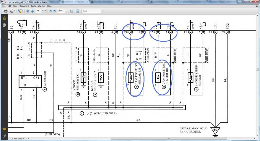
1 <--> Pin 25 of 80 pin ECU Connector CHECKED
2 <--> Pin 5 of 80 pin ECU Connector CHECKED
CAM SENSOR #1
1 <--> Pin 26 of 80 pin ECU Connector CHECKED
2 <--> Pin 6 of 80 pin ECU Connector CHECKED
CRANKSHAFT POSITION SENSOR
1 <--> Pin 7 of the 80 pin ECU Connector CHECKED
2 <--> Pin 27 of the 80 pin ECU Connector CHECKED
DIAGNOSTIC PORT
1 (FP) <--> Pin 15 of Plug C of the Big Gray Aristo Plug (should go to (SC3 IJ1-1 , SC4 IJ1-1 , MK4 IJ1-8 ))
2 (W) <--> Pin 2 of Plug E of the Big Gray Aristo Plug (should go to Pin 6 of the 40 pin ECU Connector & to (SC3 IK2-9 , SC4 IK2-9 , MK4 II1-15 ))
3 (E1) <--> Pin 11 of Plug F of the Big Gray Aristo Plug (should go to Rear Intake Manifold Ground & to (SC3 Pin 69,79,80 of the 80 pin ECU Connector , SC4 Pin 69,79,80 of the 80 pin ECU Connector , MK4 IJ1-18 ))
4 (OX1)<--> Pin 48 of the 80 pin ECU Connector
5 (AB) <--> Pin 4 of Plug D of the Big Gray Aristo Plug
6 (OP1)<--> Pin 10 of Plug D of the Big Gray Aristo Plug
7 (CCo)<--> Pin 8 of Plug D of the Big Gray Aristo Plug
8 (TE1) <--> Pin 4 of Plug F of the Big Gray Aristo Plug(should go to Pin 20 of the 40 pin ECU Connector & to ( SC3 IK1-4 , SC4 IK1-4 , MK4 IJ1-5 ))
9 (TE2) <--> Pin 7 of Plug E of the Big Gray Aristo Plug (should go to Pin 19 of the 40 pin ECU Connector & to ( SC3 IK1-2 , SC4 IK1-2 , MK4 IJ1-17 ))
11 (TC)<--> Pin 6 of Plug E of the Big Gray Aristo Plug
12 (+B)<--> Pin 3 of Plug E of the Big Gray Aristo Plug (should go to (SC3 IJ1-12 & EB2-1 & Short-4 & Pin 2 of O2 Sensor , SC4 IJ1-12 & EB2-3 & Pin 2 of O2 Sensor , MK4 EA3-3 & Pin 31 of 40 pin ECU Connector ))
13 (VF1)<-->Pin 10 of Plug F of the Big Gray Aristo Plug (should go to Pin 29 of the 80 pin ECU Connector & to ( SC3 IK1-3 , SC4 IK1-3 , MK4 IJ1-13 ))
16 (TS)<--> Pin 5 of Plug F of the Big Gray Aristo Plug
18 (TEM)<--> Pin 5 of Plug D of the Big Gray Aristo Plug
19 (IG-) <--> Pin 1 of the 4 pin Igniter Connector
22 (WA) <--> PIn 7 of Plug D of the Big Gray Aristo Plug
23 (WB) <--> Pin 11 of Plug D of the Big Gray Aristo Plug
GROUND - Front Intake Manifold
1 <--> Pin 2 of Noise Filter <--> Pin 4 of the 4 pin ECU CONNECTOR CHECKED
GROUND - Rear Intake Manifold
1 <--> Pin 69 <---> Pin 79 <--> Pin 80 of the 80 pin ECU Connector CHECKED
IACV
1 <--> Pin 34 of 80 pin ECU Connector CHECKED
2 <--> Pin 31 of 40 pin ECU Connector
3 <--> Pin 32 of 80 pin ECU Connector CHECKED
4 <--> Pin 35 of 80 pin ECU Connector CHECKED
5 <--> Pin 31 of 40 pin ECU Connector
6 <--> Pin 33 of 80 pin ECU Connector CHECKED
IGNITION COIL 1
1 <--> Pin 1 of the Noise Filter <--> Pin 2 of the 4 pin Igniter Connector <--> Pin 1 of Ignition Coil 2,3,4,5,6 <-->( SC3 IJ1-7 , SC4 EB2-2 , MK4 IJ1-1 or IJ1-9 )
2 <--> Pin 6 of the 12 Pin Igniter Connector CHECKED
IGNITION COIL 2
1 <--> Pin 1 of the Noise Filter <--> Pin 2 of the 4 pin Igniter Connector <--> Pin 1 of Ignition Coil 1,3,4,5,6 <-->( SC3 IJ1-7 , SC4 EB2-2 , MK4 IJ1-1 or IJ1-9 )
2 <--> Pin 5 of the 12 Pin Igniter Connector CHECKED
IGNITION COIL 3
1 <--> Pin 1 of the Noise Filter <--> Pin 2 of the 4 pin Igniter Connector <--> Pin 1 of Ignition Coil 1,2,4,5,6 <-->( SC3 IJ1-7 , SC4 EB2-2 , MK4 IJ1-1 or IJ1-9 )
2 <--> Pin 4 of the 12 Pin Igniter Connector CHECKED
IGNITION COIL 4
1 <--> Pin 1 of the Noise Filter <--> Pin 2 of the 4 pin Igniter Connector <--> Pin 1 of Ignition Coil 1,2,3,5,6 <-->( SC3 IJ1-7 , SC4 EB2-2 , MK4 IJ1-1 or IJ1-9 )
2 <--> Pin 10 of the 12 Pin Igniter Connector CHECKED
IGNITION COIL 5
1 <--> Pin 1 of the Noise Filter <--> Pin 2 of the 4 pin Igniter Connector <--> Pin 1 of Ignition Coil 1,2,3,4,6 <-->( SC3 IJ1-7 , SC4 EB2-2 , MK4 IJ1-1 or IJ1-9 )
2 <--> Pin 11 of the 12 Pin Igniter Connector CHECKED
IGNITION COIL 6
1 <--> Pin 1 of the Noise Filter <--> Pin 2 of the 4 pin Igniter Connector <--> Pin 1 of Ignition Coil 1,2,3,4,5 <-->( SC3 IJ1-7 , SC4 EB2-2 , MK4 IJ1-1 or IJ1-9 )
2 <--> Pin 12 of the 12 Pin Igniter Connector CHECKED
INJECTOR NO. 1
1 <--> Pin 20 of the 80 pin ECU Connector CHECKED
2 <--> (should go to (SC3 IJ1-7 or IJ1-3 & short 3 & short 5 , SC40 EB2-2 , MK4 IJ1-9))
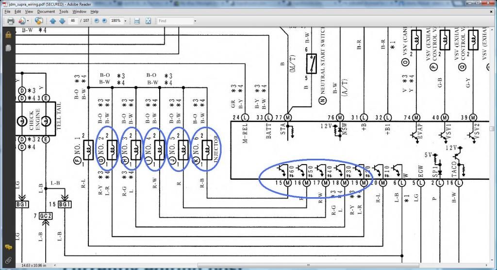
INJECTOR NO. 2
1 <--> Pin 19 of 80 pin ECU Connector CHECKED
2 <--> (should go to (SC3 IJ1-7 or IJ1-3 & short 3 & short 5 , SC40 EB2-2 , MK4 IJ1-9))
INJECTOR NO. 3
1 <--> Pin 18 of 80 pin ECU Connector CHECKED
2 <--> (should go to (SC3 IJ1-7 or IJ1-3 & short 3 & short 5 , SC40 EB2-2 , MK4 IJ1-9))
INJECTOR NO. 4
1 <--> Pin 17 of 80 pin ECU Connector CHECKED
2 <--> (should go to (SC3 IJ1-7 or IJ1-3 & short 3 & short 5 , SC40 EB2-2 , MK4 IJ1-9))
INJECTOR NO. 5
1 <--> Pin 16 of 80 pin ECU Connector CHECKED
2 <--> (should go to (SC3 IJ1-7 or IJ1-3 & short 3 & short 5 , SC40 EB2-2 , MK4 IJ1-9))
INJECTOR NO. 6
1 <--> Pin 15 of 80 pin ECU Connector CHECKED
2 <--> (should go to (SC3 IJ1-7 or IJ1-3 & short 3 & short 5 , SC40 EB2-2 , MK4 IJ1-9))
INTAKE AIR TEMP SENSOR (IAT)
1 <--> Pin 65 of 80 pin ECU Connector CHECKED
2 <--> Pin 45 of 80 pin ECU Connector CHECKED
KNOCK SENSOR 1
1 <--> Pin 50 of the 80 pin ECU Connector CHECKED
KNOCK SENSOR 2
1 <--> Pin 49 of the 80 pin ECU Connector CHECKED
MANIFOLD AIR PRESSURE SENSOR (MAP / Turbo Pressure / Vacuum Sensor )
1 <--> Pin 65 of 80 pin ECU Connector CHECKED
2 <--> Pin 62 of 80 pin ECU Connector CHECKED
3 <--> Pin 41 of 80 pin ECU Connector CHECKED
NOISE FILTER
1 <--> Pin 2 of the 4 pin Igniter Connector <--> ( SC3 IJ1-7, SC4 EB2-2 , MK4 IJ1-1 or IJ1-9 )
2 <--> Ground Connector on the Front Side of Intake Manifold <--> Pin 4 of the 4 pin Igniter Connector CHECKED
O/D DIRECT CLUTCH SPEED SENSOR (O/D)
1 <--> Pin 1 of 80 pin ECU Connector CHECKED
2 <--> Pin 21 of 80 pin ECU Connector CHECKED
OIL LEVEL SENSOR PLUG
1 <--> Pin 1 of Plug D of Big Gray Aristo Plug (should go to (SC3 IK2-10 , SC4 IK2-10 , MK4 II1-33 ))
2 <--> Pin 7 of Plug F of Big Gray Aristo Plug(should go to ( SC3 / SC4 / MK4 Rear Intake Manifold Ground for all ))
OIL PRESSURE PLUG
1 <--> Pin 8 of Plug F of the Aristo Plug (should go to ( SC3 IK1-20 , SC4 IK1-20 , MK4 II1-25 ))
STARTER
1 <--> Pin 1 of Plug F of Big Gray Aristo Plug (should go to (SC3 EB2-1 , SC4 ED2-2 then EB2-1 , MK4 EA3-1 ))
THROTTLE POSITION SENSOR
1 <--> Pin 41 of the 80 pin ECU Connector CHECKED
2 <--> Pin 43 of the 80 pin ECU Connector CHECKED
3 <--> Pin 64 of the 80 pin ECU Connector CHECKED
4 <--> Pin 65 of the 80 pin ECU Connector CHECKED
TRANSMISSION SOLENOID (ECT Solenoid)
1 <--> Pin 31 of 80 pin ECU Connector CHECKED
2 <--> Pin 3 of Plug E of the Big Aristo Plug (should go to (Pin 12 of the Data Link Connector & to ( SC3 IJ1-12 & EB2-1 & Short-4 , SC4 IJ1-12 & EB2-3 , MK4 EA3-3 )))
3 <--> Pin 3 of Plug E of the Big Aristo Plug (should go to (Pin 12 of the Data Link Connector & to ( SC3 IJ1-12 & EB2-1 & Short-4 , SC4 IJ1-12 & EB2-3 , MK4 EA3-3 )))
4 <--> Pin 10 of 80 pin ECU Connector CHECKED
5 <--> Pin 12 of 80 pin ECU Connector CHECKED
6 <--> Pin 13 of 80 pin ECU Connector CHECKED
7 <--> Pin 14 of 80 pin ECU Connector CHECKED
8 <--> Pin 9 of 80 pin ECU Connector CHECKED
WATER TEMPERATURE SENSOR
1 <--> Pin 65 of the 80 pin ECU Connector CHECKED
2 <--> Pin 44 of the 80 pin ECU Connector CHECKED
WATER TEMPERATURE GAUGE SENDER
1 <--> Pin 9 of Plug F of the Big Gray Aristo Plug (should go to SC3 IK1-9 , SC4 IK1-9 & Short-3 , MK4 II1-19 )
The following plugs are necessary only if you are going stock 2jzgte setup
OXYGEN SENSOR (O2)
1 <--> Pin 71 of the 80 pin ECU Connector CHECKED
2 <--> Pin 3 of Plug E of Aristo Plug <-> (Pin 12 of the Data Link Connector <--> ( SC3 IJ1-12 & EB2-1 & Short-4 , SC4 IJ1-12 & EB2-3 , MK4 EA3-3 ))
3 <--> Pin 48 of the 80 pin ECU Connector CHECKED
VSV1 ( Air Intake Control Valve )
1 <--> Pin 2 of the O2 Sensor <--> Pin 1 of the VSV3 <-> (Pin 12 of the Data Link Connector <--> ( SC3 IJ1-12 & EB2-1 & Short-4 , SC4 IJ1-12 & EB2-3 , MK4 EA3-3 ))
2 <--> Pin 40 of the 80 pin ECU Connector CHECKED
VSV2 ( Exhaust Control Valve )
1 <--> Pin 1 of VSV1 , VSV3 , VSVPMC <--> Pin 2 of the O2 Sensor <--> Pin 1 of the VSV3 <-> (Pin 12 of the Data Link Connector <--> ( SC3 IJ1-12 & EB2-1 & Short-4 , SC4 IJ1-12 & EB2-3 , MK4 EA3-3 ))
2 <--> Pin 39 of the 80 pin ECU Connector CHECKED
VSV3( Exhaust Bypass Valve )
1 <--> Pin 2 of the O2 Sensor <-->Pin 1 of the VSV1 <-> (Pin 12 of the Data Link Connector <--> ( SC3 IJ1-12 & EB2-1 & Short-4 , SC4 IJ1-12 & EB2-3 , MK4 EA3-3 ))
2 <--> Pin 38 of the 80 pin ECU Connector CHECKED
VSVEVAP ( Canister Purge )
1 <--> Pin 1 of VSV1 , VSV2 , VSV3 , VSVPMC <--> (Pin 12 of the Data Link Connector <--> ( SC3 IJ1-12 & EB2-1 & Short-4 , SC4 IJ1-12 & EB2-3 , MK4 EA3-3 ))
2 <--> Pin 74 of the 80 pin ECU Connector CHECKED
VSVPMC ( Waste Gate Valve )
1 <--> Pin 1 of VSV1 , VSV2 , VSV3 <--> Pin 2 of the O2 Sensor <--> Pin 1 of the VSV3 <-> (Pin 12 of the Data Link Connector <--> ( SC3 IJ1-12 & EB2-1 & Short-4 , SC4 IJ1-12 & EB2-3 , MK4 EA3-3 ))
2 <--> Pin 60 of the 80 pin ECU Connector CHECKED
The following plugs maybe kept or deleted depending on your seup
Sub-Throttle Position Sensor
1 <--> Pin 65 of the 80 pin ECU Connector CHECKED
2 <--> Pin 63 of the 80 pin ECU Connector CHECKED
3 <--> Pin 42 of the 80 pin ECU Connector CHECKED
4 <--> Pin 41 of the 80 pin ECU Connector CHECKED
The following plugs are usually deleted
Throttle Motor Valve
1 <--> Pin 8 of Plug C of Big Gray Aristo Plug
2 <--> Pin 11 of Plug C of Big Gray Aristo Plug
3 <--> Pin 7 of Plug C of Big Gray Aristo Plug
4 <--> Pin 4 of Plug C of Big Gray Aristo Plug
5 <--> Pin 6 of Plug C of Big Gray Aristo Plug
6 <--> Pin 3 of Plug C of Big Gray Aristo Plug
The following plug definitely will be deleted but its wires go to different body plugs or 40 pin ECU Connector or can be used for future needs
BIG GRAY ARISTO PLUG
PLUG C
1 <--> (SC3 EB1-7 & II1-1 , SC4 ED1-8 then to EB1-7 & II1-1 , MK4 II1-26 ))
2 <-->(should go to (SC3 II1-4 , SC4 ED1-4 then to II1-4 , MK4 II1-20 ))
3 <--> Extra Wire for future use CHECKED
4 <--> Extra Wire for future use CHECKED
5 <--> (should go to (SC3 EB1-1 , SC4 ED2-1 then to EB1-1 , MK4 EA1-1 & II1-10 ))
6 <--> Extra Wire for future use CHECKED
7 <--> Extra Wire for future use CHECKED
8 <--> Extra Wire for future use CHECKED
11 <--> Extra Wire for future use CHECKED
13 <--> Extra Wire for future use CHECKED
15 <--> Pin 1 (FP) of Diagnostic Port goes (should go to (SC3 IJ1-1 , SC4 IJ1-1 , MK4 IJ1-8 ))
PLUG D
1 <--> (should go to (SC3 IK2-10 , SC4 IK2-10 , MK4 II1-33 ))
4 <--> Pin 5 (AB) of Diagnostic Port
5 <--> Pin 18 (TEM) of Diagnostic Port
6 <--> Pin 63 of the 80 pin ECU Connector (Is still needed ????? remains to be seen during the merge process)
7 <--> Pin 22 (WA) of Diagnostic Port
8 <--> Pin 7 (CCo) of Diagnotic Port
9 <--> Extra Wire for future use CHECKED
10<-->Pin 6 (OP1) of Diagnostic Port
11<-->Pin 23 (WB) of Diagnostic Port
PLUG E
2 <--> Pin 2 (W) of Diagnostic Port (should go to Pin 6 of the 40 pin ECU Connector & to (SC3 IK2-9 , SC4 IK2-9 , MK4 II1-15 ))
3 <--> Pin 2 of Oxygen Sensor <--> Pin 2 & Pin 3 of Transmission Solenoid <--> (Pin 12 of the Data Link Connector <--> ( SC3 IJ1-12 & EB2-1 & Short-4 , SC4 IJ1-12 & EB2-3 , MK4 EA3-3 ))
4 <--> Pin 12 (+B) of Diagnostic Port <--> Pin 7 of A/T Indicator Switch (should go to (SC3 IJ1-12 & EB2-1 & Short-4 & Pin 2 of O2 Sensor & IK1-12 , SC4 IJ1-12 & EB2-3 & Pin 2 of O2 Sensor & IK1-12 , MK4 EA3-3 & Pin 31 of 40 pin ECU Connector & II1-7 ))
5 <--> Pin 6 of A/T Indicator Switch
6 <--> Pin 11 (TC) of Diagnostic Port
7 <--> Pin 9 (TE2) of Diagnostic Port (should go to Pin 19 of the 40 pin ECU Connector & to ( SC3 IK1-2 , SC4 IK1-2 , MK4 IJ1-17 ))
8 <--> Pin 10 of A/T Indicator Switch (should go to ( SC3 IK1-13 , SC4 IK1-13 , MK4 II1-1 ))
9 <--> Pin 2 of A/T Indicator Switch (should go to Pin 9 of the 40 pin ECU Connector & to ( SC3 IK1-16 , SC4 IK1-16 , MK4 II1-17 ))
10 <--> Pin 3 of A/T Indicator Switch (should go to Pin 10 of the 40 pin ECU Connector & to ( SC3 IK1-17 , SC4 IK1-17 , MK4 II1-27 ))
11 <--> Pin 9 of A/T Indicator Switch (should go to ( SC3 IK1-14 , SC4 IK1-14 , MK4 II1-18 ))
12 <--> Pin 5 of A/T Indicator Switch
13 <--> Pin 8 of A/T Indicator Switch (should go to Pin 7 of the 40 pin ECU Connector & to ( SC3 IK1-11 , SC4 IK1-11 , MK4 II1-36 ))
14 <--> Pin 4 of A/T Indicator Switch (should go to ( SC3 IJ1-10 , SC4 IJ1-10 , MK4 II1-23 ))
PLUG F
4 <--> Pin 8 (TE1) of Diagnostic Port ((should go to Pin 20 of the 40 pin ECU Connector & to ( SC3 IK1-4 , SC4 IK1-4 , MK4 IJ1-5 ))
5 <--> Pin 16 (TS) of Diagnostic Port
6 <--> Pin 1 of the Noise Filter <--> ( SC3 IJ1-7 , SC4 EB2-2 , MK4 IJ1-1 or IJ1-9 )
7 <--> (should go to ( SC3 / SC4 / MK4 Rear Intake Manifold Ground for all ))
8 <--> (should go to ( SC3 IK1-20 , SC4 IK1-20 , MK4 II1-25 ))
9 <--> Pin 1 of the Water Temperature Gauge Sender <--> ( SC3 IK1-9 , SC4 IK1-9 & Short-3 , MK4 II1-19 )
10<--> Pin 13 (VF1) of Diagnostic Port (should go to Pin 29 of the 80 pin ECU Connector & to ( SC3 IK1-3 , SC4 IK1-3 , MK4 IJ1-13 ))
11<--> Pin 3 (E1) of Diagnostic Port (should go to Rear Intake Manifold Ground & to (SC3 Pin 69,79,80 of the 80 pin ECU Connector , SC4 Pin 69,79,80 of the 80 pin ECU Connector , MK4 IJ1-18 ))
12 <--> ( Pin 19 of the Data Link Connector & to ( SC3 IK1-8 , SC4 IK1-8 , MK4 ))
80 PIN ECU CONNECTOR
1 <--> Pin 1 of O/D Direct Clutch Speed Sensor CHECKED
2
3 <--> Pin 2 of A/T Rotation Sensor (Speed Sensor 2) CHECKED
5 <--> Pin 2 of the Camshaft Sensor # 2 CHECKED
6 <--> Pin 2 of the Camshaft Sensor #1 CHECKED
7 <--> Pin 1 of the Crankshaft Position Sensor CHECKED
9 <--> Pin 8 of Transmission Solenoid CHECKED
10 <--> Pin 4 of Transmission Solenoid CHECKED
12 <--> Pin 5 of Transmission Solenoid CHECKED
13 <--> Pin 6 of Transmission Solenoid CHECKED
14 <--> Pin 7 of Transmission Solenoid CHECKED
15 <--> Pin 1 of the Injector No. 6 CHECKED
16 <--> Pin 1 of the Injector No. 5 CHECKED
17 <--> Pin 1 of the Injector No. 4 CHECKED
18 <--> Pin 1 of the Injector No. 3 CHECKED
19 <--> Pin 1 of the Injector No. 2 CHECKED
20 <--> Pin 1 of the Injector No. 1 CHECKED
21 <--> Pin 2 of O/D Direct Clutch Speed Sensor CHECKED
23 <--> Pin 1 of A/T Rotation Speed Sensor (Speed Sensor 2) CHECKED
24 <--> Pin 2 of the A/T Fluid Temp Sensor CHECKED
25 <--> Pin 1 of the Camshaft Sensor #2 CHECKED
26 <--> Pin 1 of the Camshaft Sensor #1 CHECKED
27 <--> Pin 2 of the Crankshaft Position Sensor CHECKED
30
31 <--> Pin 1 of Transmission Solenoid CHECKED
32 <--> Pin 3 of IACV CHECKED
33 <--> Pin 6 of IACV CHECKED
34 <--> Pin 1 of IACV CHECKED
35 <--> Pin 4 of IACV CHECKED
38 <--> Pin 2 of the VSV3 CHECKED
39 <--> Pin 2 of the VSV2 CHECKED
40 <--> Pin 2 of the VSV1 CHECKED
41 <--> Pin 1 of the TPS <--> Pin 4 of the Sub-TPS <--> Pin 3 of MAP CHECKED
42 <--> Pin 3 of the Sub-TPS CHECKED
43 <--> Pin 2 of the TPS CHECKED
44 <--> Pin 2 of the Water Temperature Sensor CHECKED
45 <--> Pin 2 of the Intake Air Temp Sensor CHECKED
48 <--> Pin 3 of the O2 Sensor CHECKED
49 <--> Pin 1 of the Knock Sensor 1 CHECKED
50 <--> Pin 1 of the Knock Sensor 1 CHECKED
51
52 <--> Pin 7 of the 12 pin Igniter Connector CHECKED
53 <--> Pin 8 of the 12 pin igniter Connector CHECKED
54 <--> Pin 9 of the 12 pin igniter Connector CHECKED
55 <--> Pin 3 of the 12 pin igniter Connector CHECKED
56 <--> Pin 2 of the 12 pin Igniter Connector CHECKED
57 <--> Pin 1 of the 12 pin Igniter Connector CHECKED
58 <--> Pin 3 of the 4 pin Igniter Connector CHECKED
59
60 <--> Pin 2 of the VSVPMC CHECKED
62 <--> Pin 2 of MAP CHECKED
63 <--> Pin 2 of the Sub-TPS CHECKED
64 <--> Pin 3 of the TPS CHECKED
65 <--> Pin 1 of the Water Temperature Sensor <--> Pin 4 of the TPS <--> Pin 1 of the Sub-TPS <--> Pin 1 of A/T Fluid Temp Sensor <--> Pin 1 of IAT <--> Pin 1 of MAP CHECKED
69 <--> Rear Intake Manifold Ground CHECKED
70
71 <--> Pin 1 of the O2 Sensor CHECKED
74 <--> Pin 2 of the VSVEVAP CHECKED
79 <--> Rear Intake Manifold Ground CHECKED
80 <--> Rear Intake Manifold Ground CHECKED
4 PIN IGNITER CONNECTOR
1 <--> Pin 12 of Plug F of Aristo plug <--> ( Pin 19 of the Data Link Connector <--> ( SC3 IK1-8 , SC4 IK1-8 , MK4 ))
2 <--> Pin 6 of Plug F of Aristo plug <--> Pin 1 of the Noise Filter <--> ( SC3 IJ1-7 , SC4 EB2-2 , MK4 IJ1-1 or IJ1-9 )
3 <--> Pin 58 of the 80 pin ECU connector CHECKED
4 <--> Ground Connector on the Front Side of Intake Manifold <--> Pin 2 of the Noise filter Connector CHECKED
12 PIN IGNITER CONNECTOR
1 <--> Pin 57 of the 80 pin ECU connector CHECKED
2 <--> Pin 56 of the 80 pin ECU connector CHECKED
3 <--> Pin 55 of the 80 pin ECU connector CHECKED
4 <--> Pin 2 of the Ignition Coil Connector 3 CHECKED
5 <--> Pin 2 of the Ignition Coil Connector 2 CHECKED
6 <--> Pin 2 of the Ignition Coil Connector 1 CHECKED
7 <--> Pin 52 of the 80 pin ECU connector CHECKED
8 <--> Pin 53 of the 80 pin ECU connector CHECKED
9 <--> Pin 54 of the 80 pin ECU connector CHECKED
10 <--> Pin 2 of the Ignition Coil Connector 4 CHECKED
11 <--> Pin 2 of the Ignition Coil Connector 5 CHECKED
12 <--> Pin 2 of the Ignition Coil Connector 6 CHECKED
AC COMPRESSOR PLUG
1 <--> Pin 1 of Plug C of the Aristo Plug (should go to (SC3 EB1-7 & II1-1 , SC4 ED1-8 then to EB1-7 & II1-1 , MK4 II1-26 ))
2 <--> Pin 2 of Plug C of the Aristo Plug (should go to (SC3 II1-4 , SC4 ED1-4 then to II1-4 , MK4 II1-20 ))
4 <--> Pin 5 of Plug C of the Aristo Plug (should go to (SC3 EB1-1 , SC4 ED2-1 then to EB1-1 , MK4 EA1-1 & II1-10 ))
A/T FLUID TEMP SENSOR
1 <--> Pin 65 of 80 pin ECU Connector CHECKED
2 <--> Pin 24 of 80 pin ECU Connector CHECKED
A/T ROTATION SPEED SENSOR (Speed Sensor 2)
1 <--> Pin 23 of 80 pin ECU Connector CHECKED
2 <--> Pin 3 of 80 pin ECU Connector CHECKED
A/T INDICATOR SWITCH
2 <--> Pin 9 of Plug E of the Big Aristo Plug (should go to Pin 9 of the 40 pin ECU Connector & to ( SC3 IK1-16 , SC4 IK1-16 , MK4 II1-17 ))
3 <--> Pin 10 of Plug E of the Big Aristo Plug (should go to Pin 10 of the 40 pin ECU Connector & to ( SC3 IK1-17 , SC4 IK1-17 , MK4 II1-27 ))
4 <--> Pin 14 of Plug E of the Big Aristo Plug (should go to ( SC3 IJ1-10 , SC4 IJ1-10 , MK4 II1-23 ))
5 <--> Pin 12 of Plug E of the Big Aristo Plug
6 <--> Pin 5 of Plug E of the Big Aristo Plug
7 <--> Pin 4 of Plug E of the Big Aristo Plug (should go to ( SC3 IK1-12 , SC4 IK1-12 , MK4 II1-7 ))
8 <--> Pin 13 of Plug E of the Big Aristo Plug (should go to Pin 7 of the 40 pin ECU Connector & to ( SC3 IK1-11 , SC4 IK1-11 , MK4 II1-36 ))
9 <--> Pin 11 of Plug E of the Big Aristo Plug (should go to ( SC3 IK1-14 , SC4 IK1-14 , MK4 II1-18 ))
10 <--> Pin 8 of Plug E of the Big Aristo Plug (should go to ( SC3 IK1-13 , SC4 IK1-13 , MK4 II1-1 ))
CAM SENSOR #2
1 <--> Pin 25 of 80 pin ECU Connector CHECKED
2 <--> Pin 5 of 80 pin ECU Connector CHECKED
CAM SENSOR #1
1 <--> Pin 26 of 80 pin ECU Connector CHECKED
2 <--> Pin 6 of 80 pin ECU Connector CHECKED
CRANKSHAFT POSITION SENSOR
1 <--> Pin 7 of the 80 pin ECU Connector CHECKED
2 <--> Pin 27 of the 80 pin ECU Connector CHECKED
DIAGNOSTIC PORT
1 (FP) <--> Pin 15 of Plug C of the Big Gray Aristo Plug (should go to (SC3 IJ1-1 , SC4 IJ1-1 , MK4 IJ1-8 ))
2 (W) <--> Pin 2 of Plug E of the Big Gray Aristo Plug (should go to Pin 6 of the 40 pin ECU Connector & to (SC3 IK2-9 , SC4 IK2-9 , MK4 II1-15 ))
3 (E1) <--> Pin 11 of Plug F of the Big Gray Aristo Plug (should go to Rear Intake Manifold Ground & to (SC3 Pin 69,79,80 of the 80 pin ECU Connector , SC4 Pin 69,79,80 of the 80 pin ECU Connector , MK4 IJ1-18 ))
4 (OX1)<--> Pin 48 of the 80 pin ECU Connector
5 (AB) <--> Pin 4 of Plug D of the Big Gray Aristo Plug
6 (OP1)<--> Pin 10 of Plug D of the Big Gray Aristo Plug
7 (CCo)<--> Pin 8 of Plug D of the Big Gray Aristo Plug
8 (TE1) <--> Pin 4 of Plug F of the Big Gray Aristo Plug(should go to Pin 20 of the 40 pin ECU Connector & to ( SC3 IK1-4 , SC4 IK1-4 , MK4 IJ1-5 ))
9 (TE2) <--> Pin 7 of Plug E of the Big Gray Aristo Plug (should go to Pin 19 of the 40 pin ECU Connector & to ( SC3 IK1-2 , SC4 IK1-2 , MK4 IJ1-17 ))
11 (TC)<--> Pin 6 of Plug E of the Big Gray Aristo Plug
12 (+B)<--> Pin 3 of Plug E of the Big Gray Aristo Plug (should go to (SC3 IJ1-12 & EB2-1 & Short-4 & Pin 2 of O2 Sensor , SC4 IJ1-12 & EB2-3 & Pin 2 of O2 Sensor , MK4 EA3-3 & Pin 31 of 40 pin ECU Connector ))
13 (VF1)<-->Pin 10 of Plug F of the Big Gray Aristo Plug (should go to Pin 29 of the 80 pin ECU Connector & to ( SC3 IK1-3 , SC4 IK1-3 , MK4 IJ1-13 ))
16 (TS)<--> Pin 5 of Plug F of the Big Gray Aristo Plug
18 (TEM)<--> Pin 5 of Plug D of the Big Gray Aristo Plug
19 (IG-) <--> Pin 1 of the 4 pin Igniter Connector
22 (WA) <--> PIn 7 of Plug D of the Big Gray Aristo Plug
23 (WB) <--> Pin 11 of Plug D of the Big Gray Aristo Plug
GROUND - Front Intake Manifold
1 <--> Pin 2 of Noise Filter <--> Pin 4 of the 4 pin ECU CONNECTOR CHECKED
GROUND - Rear Intake Manifold
1 <--> Pin 69 <---> Pin 79 <--> Pin 80 of the 80 pin ECU Connector CHECKED
IACV
1 <--> Pin 34 of 80 pin ECU Connector CHECKED
2 <--> Pin 31 of 40 pin ECU Connector
3 <--> Pin 32 of 80 pin ECU Connector CHECKED
4 <--> Pin 35 of 80 pin ECU Connector CHECKED
5 <--> Pin 31 of 40 pin ECU Connector
6 <--> Pin 33 of 80 pin ECU Connector CHECKED
IGNITION COIL 1
1 <--> Pin 1 of the Noise Filter <--> Pin 2 of the 4 pin Igniter Connector <--> Pin 1 of Ignition Coil 2,3,4,5,6 <-->( SC3 IJ1-7 , SC4 EB2-2 , MK4 IJ1-1 or IJ1-9 )
2 <--> Pin 6 of the 12 Pin Igniter Connector CHECKED
IGNITION COIL 2
1 <--> Pin 1 of the Noise Filter <--> Pin 2 of the 4 pin Igniter Connector <--> Pin 1 of Ignition Coil 1,3,4,5,6 <-->( SC3 IJ1-7 , SC4 EB2-2 , MK4 IJ1-1 or IJ1-9 )
2 <--> Pin 5 of the 12 Pin Igniter Connector CHECKED
IGNITION COIL 3
1 <--> Pin 1 of the Noise Filter <--> Pin 2 of the 4 pin Igniter Connector <--> Pin 1 of Ignition Coil 1,2,4,5,6 <-->( SC3 IJ1-7 , SC4 EB2-2 , MK4 IJ1-1 or IJ1-9 )
2 <--> Pin 4 of the 12 Pin Igniter Connector CHECKED
IGNITION COIL 4
1 <--> Pin 1 of the Noise Filter <--> Pin 2 of the 4 pin Igniter Connector <--> Pin 1 of Ignition Coil 1,2,3,5,6 <-->( SC3 IJ1-7 , SC4 EB2-2 , MK4 IJ1-1 or IJ1-9 )
2 <--> Pin 10 of the 12 Pin Igniter Connector CHECKED
IGNITION COIL 5
1 <--> Pin 1 of the Noise Filter <--> Pin 2 of the 4 pin Igniter Connector <--> Pin 1 of Ignition Coil 1,2,3,4,6 <-->( SC3 IJ1-7 , SC4 EB2-2 , MK4 IJ1-1 or IJ1-9 )
2 <--> Pin 11 of the 12 Pin Igniter Connector CHECKED
IGNITION COIL 6
1 <--> Pin 1 of the Noise Filter <--> Pin 2 of the 4 pin Igniter Connector <--> Pin 1 of Ignition Coil 1,2,3,4,5 <-->( SC3 IJ1-7 , SC4 EB2-2 , MK4 IJ1-1 or IJ1-9 )
2 <--> Pin 12 of the 12 Pin Igniter Connector CHECKED
INJECTOR NO. 1
1 <--> Pin 20 of the 80 pin ECU Connector CHECKED
2 <--> (should go to (SC3 IJ1-7 or IJ1-3 & short 3 & short 5 , SC40 EB2-2 , MK4 IJ1-9))
INJECTOR NO. 2
1 <--> Pin 19 of 80 pin ECU Connector CHECKED
2 <--> (should go to (SC3 IJ1-7 or IJ1-3 & short 3 & short 5 , SC40 EB2-2 , MK4 IJ1-9))
INJECTOR NO. 3
1 <--> Pin 18 of 80 pin ECU Connector CHECKED
2 <--> (should go to (SC3 IJ1-7 or IJ1-3 & short 3 & short 5 , SC40 EB2-2 , MK4 IJ1-9))
INJECTOR NO. 4
1 <--> Pin 17 of 80 pin ECU Connector CHECKED
2 <--> (should go to (SC3 IJ1-7 or IJ1-3 & short 3 & short 5 , SC40 EB2-2 , MK4 IJ1-9))
INJECTOR NO. 5
1 <--> Pin 16 of 80 pin ECU Connector CHECKED
2 <--> (should go to (SC3 IJ1-7 or IJ1-3 & short 3 & short 5 , SC40 EB2-2 , MK4 IJ1-9))
INJECTOR NO. 6
1 <--> Pin 15 of 80 pin ECU Connector CHECKED
2 <--> (should go to (SC3 IJ1-7 or IJ1-3 & short 3 & short 5 , SC40 EB2-2 , MK4 IJ1-9))
INTAKE AIR TEMP SENSOR (IAT)
1 <--> Pin 65 of 80 pin ECU Connector CHECKED
2 <--> Pin 45 of 80 pin ECU Connector CHECKED
KNOCK SENSOR 1
1 <--> Pin 50 of the 80 pin ECU Connector CHECKED
KNOCK SENSOR 2
1 <--> Pin 49 of the 80 pin ECU Connector CHECKED
MANIFOLD AIR PRESSURE SENSOR (MAP / Turbo Pressure / Vacuum Sensor )
1 <--> Pin 65 of 80 pin ECU Connector CHECKED
2 <--> Pin 62 of 80 pin ECU Connector CHECKED
3 <--> Pin 41 of 80 pin ECU Connector CHECKED
NOISE FILTER
1 <--> Pin 2 of the 4 pin Igniter Connector <--> ( SC3 IJ1-7, SC4 EB2-2 , MK4 IJ1-1 or IJ1-9 )
2 <--> Ground Connector on the Front Side of Intake Manifold <--> Pin 4 of the 4 pin Igniter Connector CHECKED
O/D DIRECT CLUTCH SPEED SENSOR (O/D)
1 <--> Pin 1 of 80 pin ECU Connector CHECKED
2 <--> Pin 21 of 80 pin ECU Connector CHECKED
OIL LEVEL SENSOR PLUG
1 <--> Pin 1 of Plug D of Big Gray Aristo Plug (should go to (SC3 IK2-10 , SC4 IK2-10 , MK4 II1-33 ))
2 <--> Pin 7 of Plug F of Big Gray Aristo Plug(should go to ( SC3 / SC4 / MK4 Rear Intake Manifold Ground for all ))
OIL PRESSURE PLUG
1 <--> Pin 8 of Plug F of the Aristo Plug (should go to ( SC3 IK1-20 , SC4 IK1-20 , MK4 II1-25 ))
STARTER
1 <--> Pin 1 of Plug F of Big Gray Aristo Plug (should go to (SC3 EB2-1 , SC4 ED2-2 then EB2-1 , MK4 EA3-1 ))
THROTTLE POSITION SENSOR
1 <--> Pin 41 of the 80 pin ECU Connector CHECKED
2 <--> Pin 43 of the 80 pin ECU Connector CHECKED
3 <--> Pin 64 of the 80 pin ECU Connector CHECKED
4 <--> Pin 65 of the 80 pin ECU Connector CHECKED
TRANSMISSION SOLENOID (ECT Solenoid)
1 <--> Pin 31 of 80 pin ECU Connector CHECKED
2 <--> Pin 3 of Plug E of the Big Aristo Plug (should go to (Pin 12 of the Data Link Connector & to ( SC3 IJ1-12 & EB2-1 & Short-4 , SC4 IJ1-12 & EB2-3 , MK4 EA3-3 )))
3 <--> Pin 3 of Plug E of the Big Aristo Plug (should go to (Pin 12 of the Data Link Connector & to ( SC3 IJ1-12 & EB2-1 & Short-4 , SC4 IJ1-12 & EB2-3 , MK4 EA3-3 )))
4 <--> Pin 10 of 80 pin ECU Connector CHECKED
5 <--> Pin 12 of 80 pin ECU Connector CHECKED
6 <--> Pin 13 of 80 pin ECU Connector CHECKED
7 <--> Pin 14 of 80 pin ECU Connector CHECKED
8 <--> Pin 9 of 80 pin ECU Connector CHECKED
WATER TEMPERATURE SENSOR
1 <--> Pin 65 of the 80 pin ECU Connector CHECKED
2 <--> Pin 44 of the 80 pin ECU Connector CHECKED
WATER TEMPERATURE GAUGE SENDER
1 <--> Pin 9 of Plug F of the Big Gray Aristo Plug (should go to SC3 IK1-9 , SC4 IK1-9 & Short-3 , MK4 II1-19 )
The following plugs are necessary only if you are going stock 2jzgte setup
OXYGEN SENSOR (O2)
1 <--> Pin 71 of the 80 pin ECU Connector CHECKED
2 <--> Pin 3 of Plug E of Aristo Plug <-> (Pin 12 of the Data Link Connector <--> ( SC3 IJ1-12 & EB2-1 & Short-4 , SC4 IJ1-12 & EB2-3 , MK4 EA3-3 ))
3 <--> Pin 48 of the 80 pin ECU Connector CHECKED
VSV1 ( Air Intake Control Valve )
1 <--> Pin 2 of the O2 Sensor <--> Pin 1 of the VSV3 <-> (Pin 12 of the Data Link Connector <--> ( SC3 IJ1-12 & EB2-1 & Short-4 , SC4 IJ1-12 & EB2-3 , MK4 EA3-3 ))
2 <--> Pin 40 of the 80 pin ECU Connector CHECKED
VSV2 ( Exhaust Control Valve )
1 <--> Pin 1 of VSV1 , VSV3 , VSVPMC <--> Pin 2 of the O2 Sensor <--> Pin 1 of the VSV3 <-> (Pin 12 of the Data Link Connector <--> ( SC3 IJ1-12 & EB2-1 & Short-4 , SC4 IJ1-12 & EB2-3 , MK4 EA3-3 ))
2 <--> Pin 39 of the 80 pin ECU Connector CHECKED
VSV3( Exhaust Bypass Valve )
1 <--> Pin 2 of the O2 Sensor <-->Pin 1 of the VSV1 <-> (Pin 12 of the Data Link Connector <--> ( SC3 IJ1-12 & EB2-1 & Short-4 , SC4 IJ1-12 & EB2-3 , MK4 EA3-3 ))
2 <--> Pin 38 of the 80 pin ECU Connector CHECKED
VSVEVAP ( Canister Purge )
1 <--> Pin 1 of VSV1 , VSV2 , VSV3 , VSVPMC <--> (Pin 12 of the Data Link Connector <--> ( SC3 IJ1-12 & EB2-1 & Short-4 , SC4 IJ1-12 & EB2-3 , MK4 EA3-3 ))
2 <--> Pin 74 of the 80 pin ECU Connector CHECKED
VSVPMC ( Waste Gate Valve )
1 <--> Pin 1 of VSV1 , VSV2 , VSV3 <--> Pin 2 of the O2 Sensor <--> Pin 1 of the VSV3 <-> (Pin 12 of the Data Link Connector <--> ( SC3 IJ1-12 & EB2-1 & Short-4 , SC4 IJ1-12 & EB2-3 , MK4 EA3-3 ))
2 <--> Pin 60 of the 80 pin ECU Connector CHECKED
The following plugs maybe kept or deleted depending on your seup
Sub-Throttle Position Sensor
1 <--> Pin 65 of the 80 pin ECU Connector CHECKED
2 <--> Pin 63 of the 80 pin ECU Connector CHECKED
3 <--> Pin 42 of the 80 pin ECU Connector CHECKED
4 <--> Pin 41 of the 80 pin ECU Connector CHECKED
The following plugs are usually deleted
Throttle Motor Valve
1 <--> Pin 8 of Plug C of Big Gray Aristo Plug
2 <--> Pin 11 of Plug C of Big Gray Aristo Plug
3 <--> Pin 7 of Plug C of Big Gray Aristo Plug
4 <--> Pin 4 of Plug C of Big Gray Aristo Plug
5 <--> Pin 6 of Plug C of Big Gray Aristo Plug
6 <--> Pin 3 of Plug C of Big Gray Aristo Plug
The following plug definitely will be deleted but its wires go to different body plugs or 40 pin ECU Connector or can be used for future needs
BIG GRAY ARISTO PLUG
PLUG C
1 <--> (SC3 EB1-7 & II1-1 , SC4 ED1-8 then to EB1-7 & II1-1 , MK4 II1-26 ))
2 <-->(should go to (SC3 II1-4 , SC4 ED1-4 then to II1-4 , MK4 II1-20 ))
3 <--> Extra Wire for future use CHECKED
4 <--> Extra Wire for future use CHECKED
5 <--> (should go to (SC3 EB1-1 , SC4 ED2-1 then to EB1-1 , MK4 EA1-1 & II1-10 ))
6 <--> Extra Wire for future use CHECKED
7 <--> Extra Wire for future use CHECKED
8 <--> Extra Wire for future use CHECKED
11 <--> Extra Wire for future use CHECKED
13 <--> Extra Wire for future use CHECKED
15 <--> Pin 1 (FP) of Diagnostic Port goes (should go to (SC3 IJ1-1 , SC4 IJ1-1 , MK4 IJ1-8 ))
PLUG D
1 <--> (should go to (SC3 IK2-10 , SC4 IK2-10 , MK4 II1-33 ))
4 <--> Pin 5 (AB) of Diagnostic Port
5 <--> Pin 18 (TEM) of Diagnostic Port
6 <--> Pin 63 of the 80 pin ECU Connector (Is still needed ????? remains to be seen during the merge process)
7 <--> Pin 22 (WA) of Diagnostic Port
8 <--> Pin 7 (CCo) of Diagnotic Port
9 <--> Extra Wire for future use CHECKED
10<-->Pin 6 (OP1) of Diagnostic Port
11<-->Pin 23 (WB) of Diagnostic Port
PLUG E
2 <--> Pin 2 (W) of Diagnostic Port (should go to Pin 6 of the 40 pin ECU Connector & to (SC3 IK2-9 , SC4 IK2-9 , MK4 II1-15 ))
3 <--> Pin 2 of Oxygen Sensor <--> Pin 2 & Pin 3 of Transmission Solenoid <--> (Pin 12 of the Data Link Connector <--> ( SC3 IJ1-12 & EB2-1 & Short-4 , SC4 IJ1-12 & EB2-3 , MK4 EA3-3 ))
4 <--> Pin 12 (+B) of Diagnostic Port <--> Pin 7 of A/T Indicator Switch (should go to (SC3 IJ1-12 & EB2-1 & Short-4 & Pin 2 of O2 Sensor & IK1-12 , SC4 IJ1-12 & EB2-3 & Pin 2 of O2 Sensor & IK1-12 , MK4 EA3-3 & Pin 31 of 40 pin ECU Connector & II1-7 ))
5 <--> Pin 6 of A/T Indicator Switch
6 <--> Pin 11 (TC) of Diagnostic Port
7 <--> Pin 9 (TE2) of Diagnostic Port (should go to Pin 19 of the 40 pin ECU Connector & to ( SC3 IK1-2 , SC4 IK1-2 , MK4 IJ1-17 ))
8 <--> Pin 10 of A/T Indicator Switch (should go to ( SC3 IK1-13 , SC4 IK1-13 , MK4 II1-1 ))
9 <--> Pin 2 of A/T Indicator Switch (should go to Pin 9 of the 40 pin ECU Connector & to ( SC3 IK1-16 , SC4 IK1-16 , MK4 II1-17 ))
10 <--> Pin 3 of A/T Indicator Switch (should go to Pin 10 of the 40 pin ECU Connector & to ( SC3 IK1-17 , SC4 IK1-17 , MK4 II1-27 ))
11 <--> Pin 9 of A/T Indicator Switch (should go to ( SC3 IK1-14 , SC4 IK1-14 , MK4 II1-18 ))
12 <--> Pin 5 of A/T Indicator Switch
13 <--> Pin 8 of A/T Indicator Switch (should go to Pin 7 of the 40 pin ECU Connector & to ( SC3 IK1-11 , SC4 IK1-11 , MK4 II1-36 ))
14 <--> Pin 4 of A/T Indicator Switch (should go to ( SC3 IJ1-10 , SC4 IJ1-10 , MK4 II1-23 ))
PLUG F
4 <--> Pin 8 (TE1) of Diagnostic Port ((should go to Pin 20 of the 40 pin ECU Connector & to ( SC3 IK1-4 , SC4 IK1-4 , MK4 IJ1-5 ))
5 <--> Pin 16 (TS) of Diagnostic Port
6 <--> Pin 1 of the Noise Filter <--> ( SC3 IJ1-7 , SC4 EB2-2 , MK4 IJ1-1 or IJ1-9 )
7 <--> (should go to ( SC3 / SC4 / MK4 Rear Intake Manifold Ground for all ))
8 <--> (should go to ( SC3 IK1-20 , SC4 IK1-20 , MK4 II1-25 ))
9 <--> Pin 1 of the Water Temperature Gauge Sender <--> ( SC3 IK1-9 , SC4 IK1-9 & Short-3 , MK4 II1-19 )
10<--> Pin 13 (VF1) of Diagnostic Port (should go to Pin 29 of the 80 pin ECU Connector & to ( SC3 IK1-3 , SC4 IK1-3 , MK4 IJ1-13 ))
11<--> Pin 3 (E1) of Diagnostic Port (should go to Rear Intake Manifold Ground & to (SC3 Pin 69,79,80 of the 80 pin ECU Connector , SC4 Pin 69,79,80 of the 80 pin ECU Connector , MK4 IJ1-18 ))
12 <--> ( Pin 19 of the Data Link Connector & to ( SC3 IK1-8 , SC4 IK1-8 , MK4 ))
Last edited by gerrb; 01-31-14 at 08:26 PM.
01-18-14, 08:29 AM
#2134
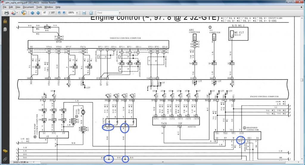
DIAGRAMS TO VERIFY PIN NUMBERING & WHERE THE WIRE GOES
*** Intake Air Temp Sensor (IAT) & Manifold Air Pressure Sensor (MAP / Turbo Pressure Sensor / Vacuum Sensor ) ***
*** Cam Sensor #1 & Cam Sensor2 ***
*** Intake Air Temp Sensor (IAT) & Manifold Air Pressure Sensor (MAP / Turbo Pressure Sensor / Vacuum Sensor ) ***

*** Cam Sensor #1 & Cam Sensor2 ***

Last edited by gerrb; 01-31-14 at 10:14 AM.
01-18-14, 06:26 PM
#2135
*** Injectors 2,3,4,5,6 ***
*** Idle Air Control Valve (IACV) ***
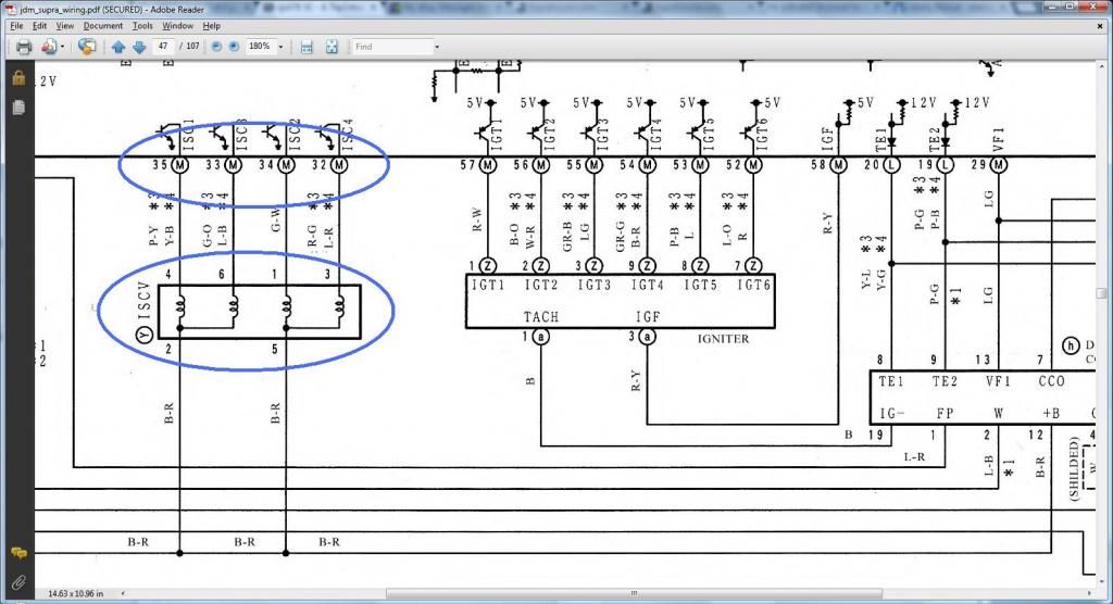
Read this diagram being on the right of the next diagram so you see continuous flow of current
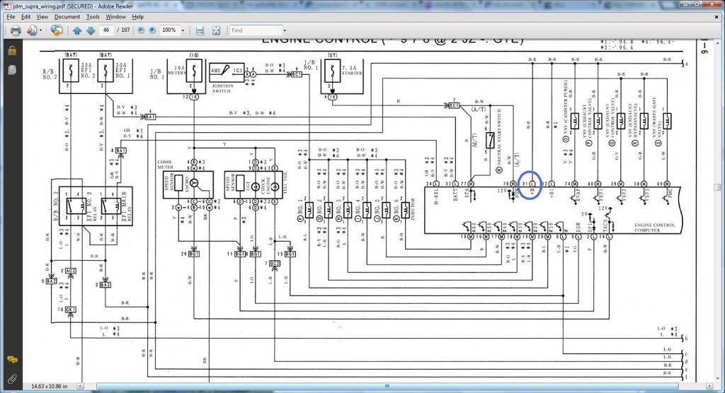

*** Idle Air Control Valve (IACV) ***

Read this diagram being on the right of the next diagram so you see continuous flow of current


Last edited by gerrb; 01-31-14 at 11:01 AM.
01-19-14, 04:16 AM
#2136
Before I go into showing where our harness should be at this point and start the merging process, please bear with me as I go back to the beginning of this 2jzgte harness build and see if I missed something or see where I can make things simpler or better. Usually at a second look , you can do things better. That I will do for now . I am not a good writer nor teacher sorry ,  , so let me review what was written so far and see if we can improve what was written so far. The number of views this thread had gotten since I started this harness build had been numerous . At times I see 40 people or more reading the thread at the same time which shows that a lot of people are interested or at least curious. Thus , I better make sure that what we have written so far is not confusing or is simple to understand.
So eventually , you guys should check back the previous pages for changes cause I know I would like to add some more details and probably pictures especially for those doing a 2jzgte swap with an auto transmission. They have more wires to worry about . Manual transmission 2jzgte swap, a lot of wires are being removed so a lot easier . Only way they are keeping the wires will be if they want to keep them as extra wires
, so let me review what was written so far and see if we can improve what was written so far. The number of views this thread had gotten since I started this harness build had been numerous . At times I see 40 people or more reading the thread at the same time which shows that a lot of people are interested or at least curious. Thus , I better make sure that what we have written so far is not confusing or is simple to understand.So eventually , you guys should check back the previous pages for changes cause I know I would like to add some more details and probably pictures especially for those doing a 2jzgte swap with an auto transmission. They have more wires to worry about . Manual transmission 2jzgte swap, a lot of wires are being removed so a lot easier . Only way they are keeping the wires will be if they want to keep them as extra wires
Last edited by gerrb; 01-19-14 at 06:42 PM.
01-19-14, 01:51 PM
#2137
Gerrb here is what I have accomplished so far on my 92 SC300 5spd Harness....I have a few questions about some of the plugs that are connected to the fuse plugs..
Here is what wires are left on the 80 pin connector that go to body plugs
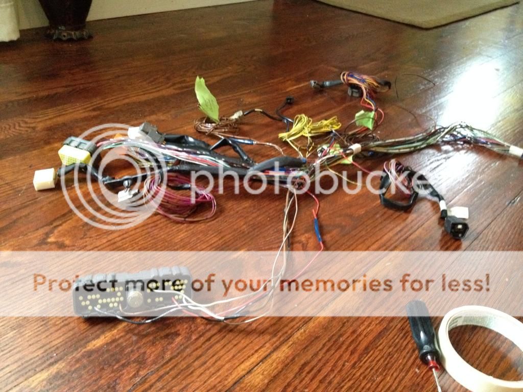
These two plugs are the ones I am referring too..The gray plug goes to the fuse plugs and the brown plug is spliced into another wire.

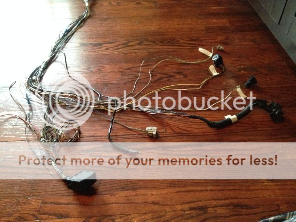


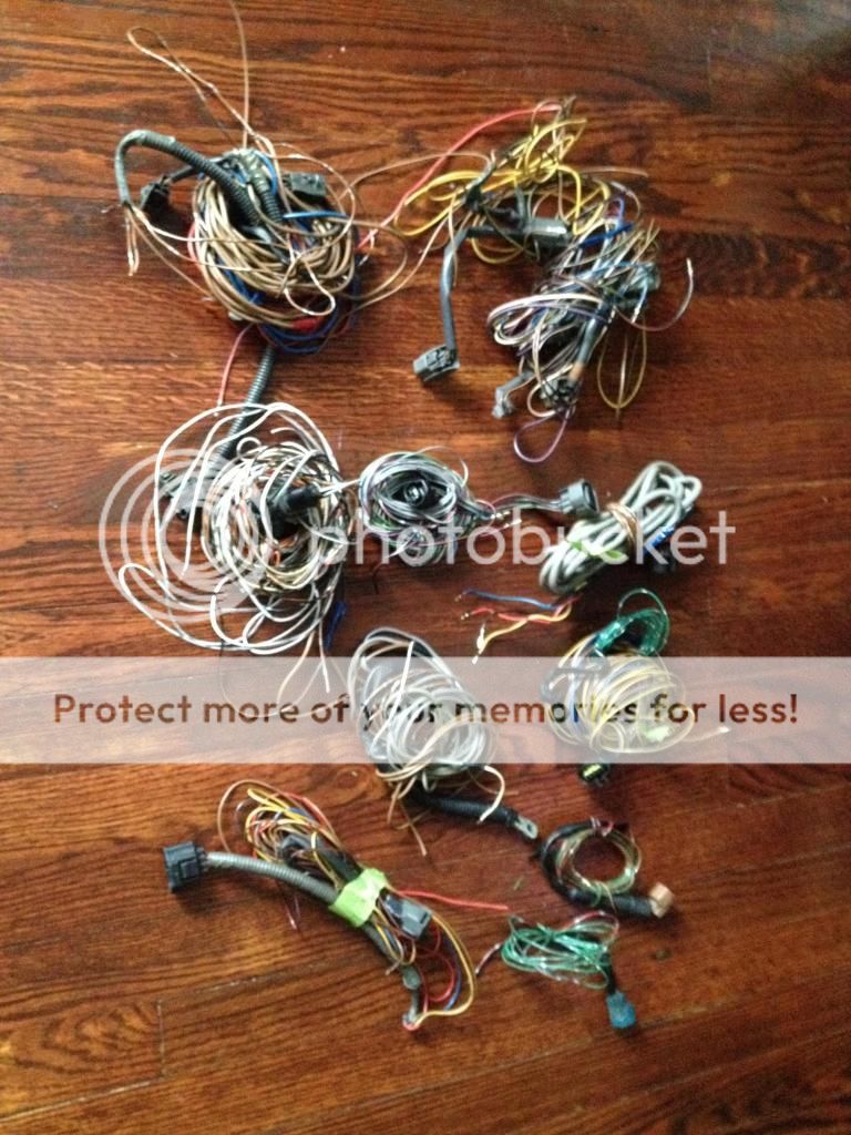
Here is my pile of wires that I was able to remove from the harness
Here is what wires are left on the 80 pin connector that go to body plugs

These two plugs are the ones I am referring too..The gray plug goes to the fuse plugs and the brown plug is spliced into another wire.


Here is my pile of wires that I was able to remove from the harness
 01-19-14, 02:12 PM
#2138
Driver School Candidate

Join Date: Jan 2014
Location: Nyc
Posts: 41
Likes: 0
Received 0 Likes
on
0 Posts
I understand the part of the whole extending certain wires and the base near the mail plug and checking then along with connectors . But my question is since I will be doing this swap in a 350z , what and how do I merge the harness/plugs in irder to retain factory functions , along with possible use of reaction control and what not ?
01-19-14, 04:54 PM
#2139
Guys . I will answer your questions later once I am done going through everything I have written so far .
Let me finish going through and editing my previous posts. I am organizing the information better, adding more details and pictures that could really help in understanding the process , proof reading so spelling and grammar can be checked too...... so please just bear with me.
I promise you , when I am done editing , you will have more details and pictures that will help you understand the process better.... like I have explained better what THE DRILL is , I am adding all the actual plugs / pins where every wire goes which include the plugs (body plugs) distinct for the SC300 , SC400 and Supra MKIV which not like before I just wrote "needs to go to a body plug" .
So I advise you to go through the pages again.... sorry about that . It is just that when you re-read what you have written , you find out that you left out some details and pictures that will help explain better the process. I told you , am not a writer nor a teacher .. lol. But I promise , it will be worth the wait !
At this point , you will know where I am or which post I am currently editing cause I will put a big caption on the post "CURRENTLY EDITING POST" . That means whatever is before that particular post , I have gone through them and added whatever I wanted to add.
Last edited by gerrb; 01-20-14 at 05:17 AM.
01-20-14, 02:10 PM
#2140
Took some time out from that 2jzgte harness build thread ... damn, I hate being a writer or a teacher. It gives me a lot of headaches. It had been consuming me so I had to stop working on it for a couple of days  . But I will get back with it ...
Today , I decided to spend some time with working on my Red Mamba 2 .
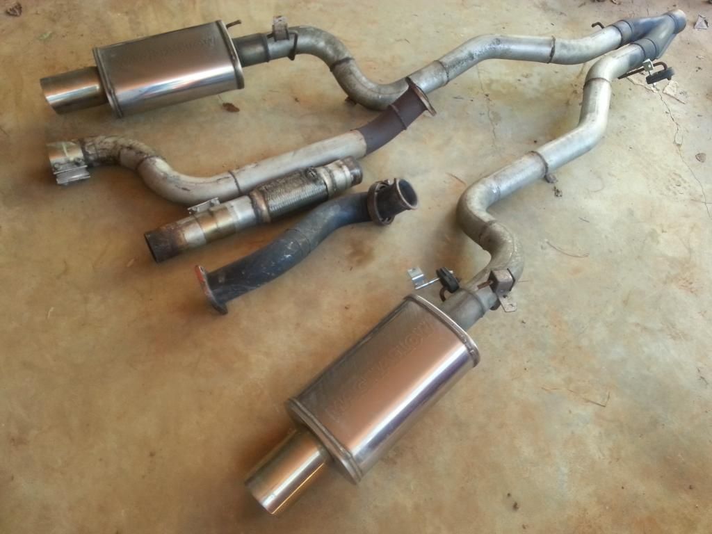
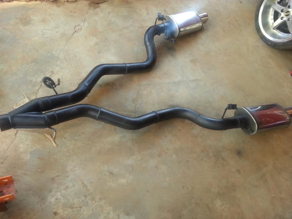
This dual 3" exhaust came from Jay then Mark then Lo and thanks to all of you my friends , it is going to the Red Mamba 2. It came with the 3" downpipe / midpipe. I believe Jay made 775 on E85 . I will instead get a 4" downpipe and midpipe to go with this dual exhaust since I am aiming for more power on the Red Mamba 2.
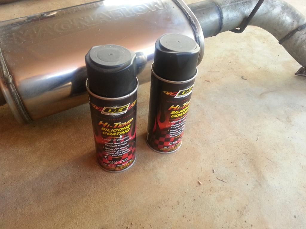
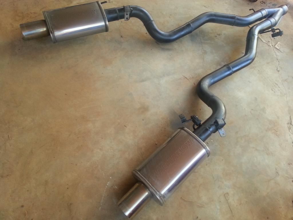
Got some more DEI high temp silicone paint so did paint the exhaust
Painted
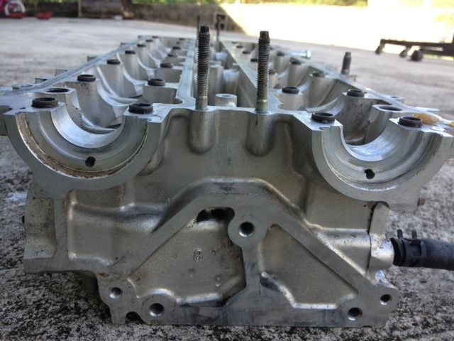
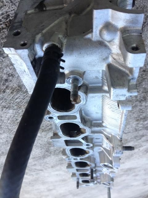
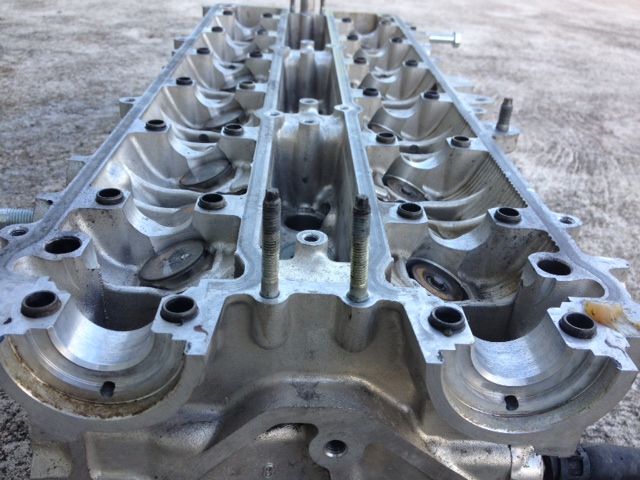
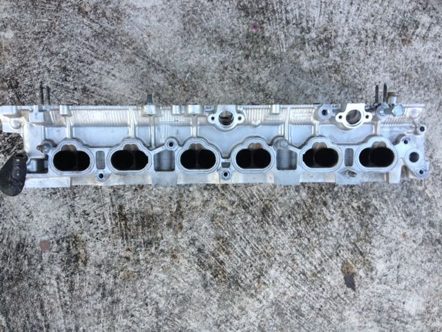
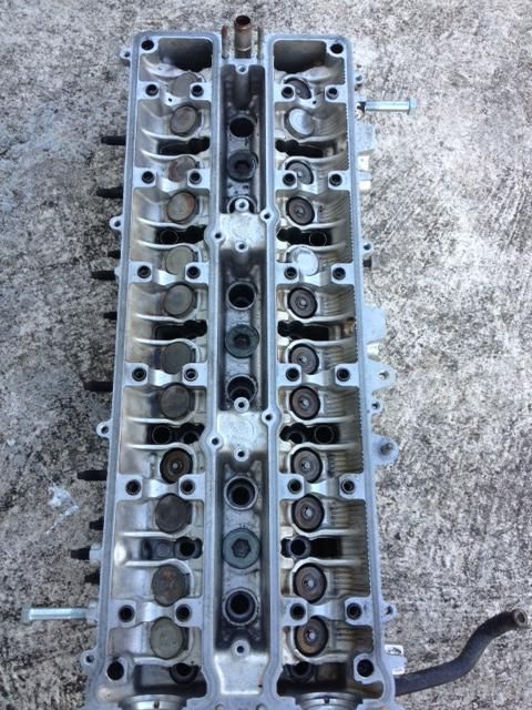
I have been slowly gathering parts for the stroker build .I found a real good deal on a 2jzgte head shipped for $250 yesterday on SF. I have never seen one that low. Although , I would toss out all its internals that's why I was waiting for a good sale for a head that was never been decked or milled. I just needed a good core. I am going all Ferrea Valvetrain for this head. Patience I guess pays off at times.
Here are some of the pictures. The cam caps are not pictured but the head comes with them.
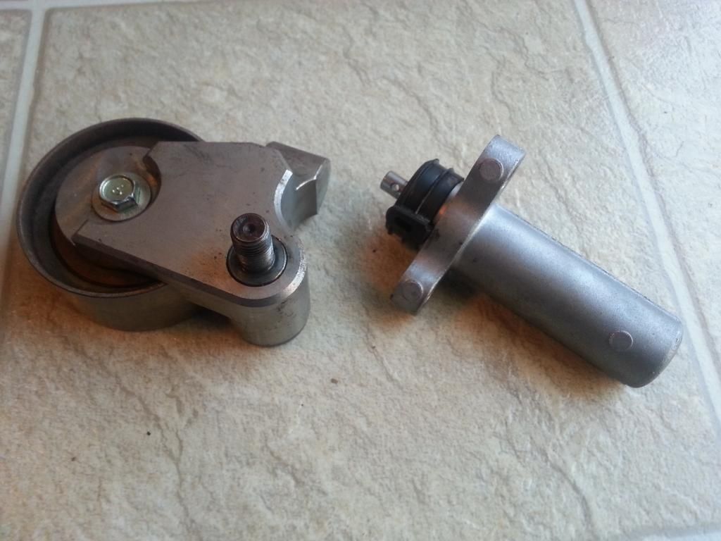
Also got a billet tensioner . At high RPMs the stock ones can break . if your engine is interference because of your aftermarket cams , desctruction inside your engine is bound to happen if that stock timing belt tensioner brakes.
. But I will get back with it ...Today , I decided to spend some time with working on my Red Mamba 2 .
This dual 3" exhaust came from Jay then Mark then Lo and thanks to all of you my friends , it is going to the Red Mamba 2. It came with the 3" downpipe / midpipe. I believe Jay made 775 on E85 . I will instead get a 4" downpipe and midpipe to go with this dual exhaust since I am aiming for more power on the Red Mamba 2.

Got some more DEI high temp silicone paint so did paint the exhaust

Painted


I have been slowly gathering parts for the stroker build .I found a real good deal on a 2jzgte head shipped for $250 yesterday on SF. I have never seen one that low. Although , I would toss out all its internals that's why I was waiting for a good sale for a head that was never been decked or milled. I just needed a good core. I am going all Ferrea Valvetrain for this head. Patience I guess pays off at times.
Here are some of the pictures. The cam caps are not pictured but the head comes with them.


Also got a billet tensioner . At high RPMs the stock ones can break . if your engine is interference because of your aftermarket cams , desctruction inside your engine is bound to happen if that stock timing belt tensioner brakes.

Last edited by gerrb; 01-21-14 at 02:38 AM.
01-20-14, 02:55 PM
#2141
Gerrb here is what I have accomplished so far on my 92 SC300 5spd Harness....I have a few questions about some of the plugs that are connected to the fuse plugs..
Here is what wires are left on the 80 pin connector that go to body plugs
These two plugs are the ones I am referring too..The gray plug goes to the fuse plugs and the brown plug is spliced into another wire.
Here is my pile of wires that I was able to remove from the harness
Here is what wires are left on the 80 pin connector that go to body plugs
These two plugs are the ones I am referring too..The gray plug goes to the fuse plugs and the brown plug is spliced into another wire.
Here is my pile of wires that I was able to remove from the harness
With the amount of wires you took out , I assume it is an SC300 manual transmission. What year is it ?
Now , you know that the starter wire on your Aristo 2jzgte harness should go to where that black plug goes which is to one of the fuse plugs.
For the AC plug , the same thing , make sure your Aristo 2jzgte harness AC plug wires goes to where the wires of that plug goes.
I have been modiffying my write-up and have now included what wire goes to what body plug .. as you can see on post 2004 on this page https://www.clublexus.com/forums/bui...mkivs-134.html . I just took time out cause it had been consuming me ... headaches ... with the details . I guess I can't be a writer or a teacher. But I will get back at it.
So once I have modified those posts where the AC and Starter plug are , you will see that the body plugs and their pins will be the same to where yours are now.
I understand the part of the whole extending certain wires and the base near the mail plug and checking then along with connectors . But my question is since I will be doing this swap in a 350z , what and how do I merge the harness/plugs in irder to retain factory functions , along with possible use of reaction control and what not ?
I know you are doing one for a 350z. It is the process that you should learn. You cannot verbatim follow what I wrote since I am doing a swap on an SC300. But if you are able to understand WHY is this being done , WHY is that being done , then you could apply it to your Aristo 2jzgte harness and 350z engine harness. You will need to extract from that 350z engine harness those plugs you will merge to your Aristo 2jzgte harness.
Last edited by gerrb; 01-20-14 at 03:11 PM.
01-20-14, 03:35 PM
#2143
 .. it was right there ..lmaol. My mind ain't right yet. I honestly was having a headache after revising post 2004 today of the 2jzgte harness build thread. I went over that post over and over just to make sure I get the message accross in a simple way that could be understood my many....lol. .
 But looking at the amount of wires you took out , no auto transmission plugs so I was positive it was 5 speed !
01-21-14, 07:56 PM
#2144
Lexus Champion
iTrader: (13)
Join Date: Feb 2008
Location: Sacramento
Posts: 2,187
Likes: 0
Received 0 Likes
on
0 Posts
Ive had the luck of building a harness from scratch excluding the sensor plugs. Its a bit time consuming but it was a really good experience. I was able to route the wires however i wanted. This is one of the best build threads ive seen.
01-22-14, 05:01 AM
#2145
I have been adding a lot of really nice informations like what Body Plug a wire should go and at what pin. I have been adding Wiring Diagrams for people to be able to verify the Informations I have been writing on the harness build thread . I have also shown on the first set of plugs we have worked on , how do you get to know where such a wire go to a SC300 , SC400 and MKIV body plug. That is, how the PROs get to deduce where to connect stuff by reading the particular diagram of a car they are installing the Aristo 2jzgte harness.
It is very time consuming with all the detailed explanations and diagrams I have to modify through PAINT to show connectivities. That is the reason why it is taking me a lot of time to do the editing. But I will assure you , people will get to understand the process better . It seems to be a daunting task to make a 2jzgte wiring harness but now that I am laying out the details and the hard work done , it should be a breeze .
Well , a title for the new thread when all these informations will be copied into a thread for the Performance Section had already been suggested by our moderator Mark (1jzpwrd) ... "2jzgte Wiring Harness Made Easy" ... maybe other cool titles can be suggested. But I just really hope it helps a lot of people after the hard work and lots of time I have put into this write-up.
Last edited by gerrb; 01-22-14 at 07:35 AM.