2jzGTE SCs - The Siblings of my Supra MKIV Toys
 12-10-15, 08:15 AM
#3391
Gerry,
Love everything about the bay but that crinkle paint on radiator, shroud and fuse box, yeah, that just doesn't go well with the black and red. If they were painted black with a sheen to them I think would look a 1000 times better. Just my 2 cents.
Shane
Love everything about the bay but that crinkle paint on radiator, shroud and fuse box, yeah, that just doesn't go well with the black and red. If they were painted black with a sheen to them I think would look a 1000 times better. Just my 2 cents.
Shane
 12-10-15, 08:43 AM
#3392

soooo real street just made a 1851hp engine using their engine dyno. roughly 1600whp.
custom pistons, tuff rods, acl bearings, arp main studs, and billet main caps. block is unfilled, stock port head, and stock oil system. squirters have been blocked off.
that's insane power for a just a 3.0.... wow
custom pistons, tuff rods, acl bearings, arp main studs, and billet main caps. block is unfilled, stock port head, and stock oil system. squirters have been blocked off.
that's insane power for a just a 3.0.... wow
 . The Black Pearl being a rare 1997 SC300 5 speed , I might as well give it a really good drive train that is why a V160 is in there and to follow is a built engine that should make +1500rwhp. . Those wrinkled parts do not look good in pictures but every one who had been to my place and seen the wrinkled parts on my engine bays all liked it. I don't know why in pictures it looks rubbish but in person it looks elegant and really nice , at least to me. But once I get tired of it , I can always change and paint it to plain shiny black .
After 3 years and 9 months from the time I started my first 2jzgte swap and this build thread , I now have 4 2jzgte SCs . Thanks a lot for those who followed the build thread. It is the most viewed build thread with over 596,900 views, 3390 posts in 227 pages. That is an average of over 434 views / clicks every day for the past 3 yrs & 9 months (1370 days) . I can't thank every one enough for making this thread the most viewed build thread on Clublexus.
I guess bad experiences had help and forced me to do my own thing when it comes to my toys. Things happen for a reason. You get to know people for who they truly are especially behind you . A lot of people are only after the money or how they will benefit from you or some are simply hypocrites . Good in front of you and behind you are pieces of sh?t . Haters will hate . Many times fueled by envy . But when done wrong you are forced to achieve or do things you have never done before. As I have said many times on this thread , I am not a mechanic and will never pretend to be one cause I am not. But these cars are a living proof that it is not rocket science tinkering with the JZ motors .... just put your heart and soul into one thing and you too can do it.
SC# 1 - Red Mamba One

SC#2 - Red Mamba Two

SC#3 - OldMan's Tan

SC#4 - Black Pearl

Last edited by gerrb; 12-18-15 at 07:25 AM.
12-12-15, 11:45 AM
#3395
The 4th (2jzgte with V160 6speed) is not yet driveable since there is no engine harness yet . As mentioned on my previous posts I have yet to do it . Reason why it is not yet on my signature .
All the first three, I can give you a ride any time !
!
.All the first three, I can give you a ride any time
!
Last edited by gerrb; 12-12-15 at 03:54 PM.
12-14-15, 03:13 AM
#3398
Wiring Harness Write - Up for a 2jzgte VVT-i Swap
For those who are doing a Non - VVTi 2jzgte swap harness, follow an older thread I made -> https://www.clublexus.com/forums/per...made-easy.html
Non VVTI and VVTI 2jzgte engines have a lot of differences on their harnesses so you cannot use one into the other .
For those who are confused in following the older thread linked above and cannot comprehend what is written there , please don't even try doing this wiring harness. It is no different. A number of people told me that they were able to do their own harness following what was written there.I don't know how I can explain things simpler than I already did on that thread. Am trying to teach you a methodology and help you understand what you are doing and not just telling you take this wire and put it on pin 1 of plug 1. Knowing how things work on your harness enables you to easily troubleshoot your car later on. So if it confuses the hell out of you , get your harness done by the professionals or those who can do it. Your engine harness is one if not the most important part of your swap. You do something wrong , you can set your car on fire or even your house if the car is inside the garage and I have seen it happen in a shop whose people work on cars for a living .
And don't ask me to do a harness for you because I am not gonna do it. I don't work on other people's car except if it is a close friend who asks for my help and is local cause I want to be there when the car is first started so to make sure everything is alright. The wiring harness for this swap is a bit more complicated due to the fact that all the 2jzgte vvti ECU plugs are different . There is more work involved. Well not really more or complicated . It is just that you need a better understanding of what is going on. Thus a disclaimer ... I won't be held responsible for any damage by anyone who tries to follow and do whatever is on my threads.
For the past two weeks, I was in a dilemma ... I wasn't decided on what kind of engine harness I will do for my 4th SC which is the rare 1 of 120 1997 SC300 original 5 speed . Currently , I have dropped a stock 2jzgte vvti with a v160 6 speed transmission on the engine bay . I know it is already rare for a 1 of 120 to have a 2jzgte 6 speed , but in the future I want it to have a built 2jzgte VVT-i engine from RealStreetPerformance (at least an RS1600 series) making at least +1500rwhp which means I will have an aftermarket intake manifold and an aftermarket ECU . That leads me to my dilemma .. what kind of harness will I build for this car now knowing that the ECU plugs of the Stock 2jzgte VVTi are different from the ECU plugs of any aftermarket ECU. Even that of the Non-VVTi 2jzgte ecu plugs are different . Wiring is totally different from NON VVTIs since they function a bit differently in stock form . VVTIs use wasted spark for ignition (only 3 coils ) and has a different igniter . It is MAF based. It has a VVTi solenoid. The intake manifold and throttle body are configured differently. Non VVTIs have an IACV on the intake plenum and the VVTIs do not cause they have incorporated Intake Air Control on the throttle body, thus wiring is different . VVTI throttle body in a way is FBW (Fly By Wire) . It has an Accelerator Pedal Position Sensor which the Non VVTIs do not have. IF you are using an auto transmission , it adds to the complexity cause there is also a difference on the transmission connector/plug controlling the solenoids.
Now , If I do a stock 2jzgte vvti wiring harness for my 4th SC then I will have to do another one or modify this one when my built VVTi engine arrives since it will be using 6 coils , a different igniter, a different intake , No MAF , other wires needed for sensors to implement failsafe procedures, and so on. Thus the Dilemma
 . And I need to get this 4th SC running soon or my wife will keep on bitc?ing about the car not running and needs to go to the junkyard. J/K ... my wife never meddled or bitc?ed about my toys to be honest
  , even if she doesn't understand why I have 8 2jzgte toys now. Neither do I understand to be honest why I have 4 SCs with 2jzgte , lmaol. It is a sickness !
Along the process as I do this write-up , pretty sure there will be comments or other people who will post on this build thread. For you to know that a post is part of the VVTi Wiring Harness Write UP , just look at the post title. I will write "2JZGTE VVTi Wiring Harness" on every post that should be a part of the write-up .
I have decided to do a stock 2jzgte VVTi harness for now which means vvti ecu with its corresponding plugs instead of the non vvti 40 / 80 pin plugs which aftermarket ECUs uses for the 2jzgte non vvti so the write up can help a lot of people doing the 2jzgte VVTI swap on an SC or MKIV (SC & MKIV differences will be on the Body Plugs) . I will just modify it later on when the time comes I am in the process of installing my built VVTi power plant. For now, I just want the Black Pearl to be running .
I have a v160 6speed on this 4th SC of mine (Black Pearl) so I might just have to describe the auto trans wiring but not actually do it.. let us see.
To start with , here is a picture of the 2jzgte vvti harness so you can familiarize yourself with it.

ECU and Igniter plugs , Diagnostic Port and plugs that go to the body loom

Auto Trans Plugs

Injectors , Cam sensor (VVTi only has one) , Map sensor and VSV plugs

Coils and VSV plugs

MAF , coolant , Crank Sensor , O2 sensor plugs

Injector #1 and other aristo connector plugs

The familiar SC300 engine harness from a 1997 SC300 with Auto Trans

2jzgte VVTi ECU plus vis-a-vis the 40/80 pin ECU plugs of the 1997 SC300 ( used also by the 2jzgte non VVTI ECUs) and SC300 body plugs

NOTE : When ordering a 2jzgte vvti swap , I would advise that you get the ECU WITHOUT THE IMMOBILIZER ... part number 89661-3A470 . You will have less problems
For those who are doing a Non - VVTi 2jzgte swap harness, follow an older thread I made -> https://www.clublexus.com/forums/per...made-easy.html
Non VVTI and VVTI 2jzgte engines have a lot of differences on their harnesses so you cannot use one into the other .
For those who are confused in following the older thread linked above and cannot comprehend what is written there , please don't even try doing this wiring harness. It is no different. A number of people told me that they were able to do their own harness following what was written there.I don't know how I can explain things simpler than I already did on that thread. Am trying to teach you a methodology and help you understand what you are doing and not just telling you take this wire and put it on pin 1 of plug 1. Knowing how things work on your harness enables you to easily troubleshoot your car later on. So if it confuses the hell out of you , get your harness done by the professionals or those who can do it. Your engine harness is one if not the most important part of your swap. You do something wrong , you can set your car on fire or even your house if the car is inside the garage and I have seen it happen in a shop whose people work on cars for a living .
And don't ask me to do a harness for you because I am not gonna do it. I don't work on other people's car except if it is a close friend who asks for my help and is local cause I want to be there when the car is first started so to make sure everything is alright. The wiring harness for this swap is a bit more complicated due to the fact that all the 2jzgte vvti ECU plugs are different . There is more work involved. Well not really more or complicated . It is just that you need a better understanding of what is going on. Thus a disclaimer ... I won't be held responsible for any damage by anyone who tries to follow and do whatever is on my threads.
For the past two weeks, I was in a dilemma ... I wasn't decided on what kind of engine harness I will do for my 4th SC which is the rare 1 of 120 1997 SC300 original 5 speed . Currently , I have dropped a stock 2jzgte vvti with a v160 6 speed transmission on the engine bay . I know it is already rare for a 1 of 120 to have a 2jzgte 6 speed , but in the future I want it to have a built 2jzgte VVT-i engine from RealStreetPerformance (at least an RS1600 series) making at least +1500rwhp which means I will have an aftermarket intake manifold and an aftermarket ECU . That leads me to my dilemma .. what kind of harness will I build for this car now knowing that the ECU plugs of the Stock 2jzgte VVTi are different from the ECU plugs of any aftermarket ECU. Even that of the Non-VVTi 2jzgte ecu plugs are different . Wiring is totally different from NON VVTIs since they function a bit differently in stock form . VVTIs use wasted spark for ignition (only 3 coils ) and has a different igniter . It is MAF based. It has a VVTi solenoid. The intake manifold and throttle body are configured differently. Non VVTIs have an IACV on the intake plenum and the VVTIs do not cause they have incorporated Intake Air Control on the throttle body, thus wiring is different . VVTI throttle body in a way is FBW (Fly By Wire) . It has an Accelerator Pedal Position Sensor which the Non VVTIs do not have. IF you are using an auto transmission , it adds to the complexity cause there is also a difference on the transmission connector/plug controlling the solenoids.
Now , If I do a stock 2jzgte vvti wiring harness for my 4th SC then I will have to do another one or modify this one when my built VVTi engine arrives since it will be using 6 coils , a different igniter, a different intake , No MAF , other wires needed for sensors to implement failsafe procedures, and so on. Thus the Dilemma
. And I need to get this 4th SC running soon or my wife will keep on bitc?ing about the car not running and needs to go to the junkyard. J/K ... my wife never meddled or bitc?ed about my toys to be honest , even if she doesn't understand why I have 8 2jzgte toys now. Neither do I understand to be honest why I have 4 SCs with 2jzgte , lmaol. It is a sickness !Along the process as I do this write-up , pretty sure there will be comments or other people who will post on this build thread. For you to know that a post is part of the VVTi Wiring Harness Write UP , just look at the post title. I will write "2JZGTE VVTi Wiring Harness" on every post that should be a part of the write-up .
I have decided to do a stock 2jzgte VVTi harness for now which means vvti ecu with its corresponding plugs instead of the non vvti 40 / 80 pin plugs which aftermarket ECUs uses for the 2jzgte non vvti so the write up can help a lot of people doing the 2jzgte VVTI swap on an SC or MKIV (SC & MKIV differences will be on the Body Plugs) . I will just modify it later on when the time comes I am in the process of installing my built VVTi power plant. For now, I just want the Black Pearl to be running .
I have a v160 6speed on this 4th SC of mine (Black Pearl) so I might just have to describe the auto trans wiring but not actually do it.. let us see.
To start with , here is a picture of the 2jzgte vvti harness so you can familiarize yourself with it.

ECU and Igniter plugs , Diagnostic Port and plugs that go to the body loom

Auto Trans Plugs

Injectors , Cam sensor (VVTi only has one) , Map sensor and VSV plugs

Coils and VSV plugs

MAF , coolant , Crank Sensor , O2 sensor plugs

Injector #1 and other aristo connector plugs

The familiar SC300 engine harness from a 1997 SC300 with Auto Trans

2jzgte VVTi ECU plus vis-a-vis the 40/80 pin ECU plugs of the 1997 SC300 ( used also by the 2jzgte non VVTI ECUs) and SC300 body plugs

NOTE : When ordering a 2jzgte vvti swap , I would advise that you get the ECU WITHOUT THE IMMOBILIZER ... part number 89661-3A470 . You will have less problems
Last edited by gerrb; 01-10-16 at 03:57 AM.
12-14-15, 07:12 AM
#3399
Again BIG THANKS to the owners of the following site where some info and pictures were copied so you have an idea what the wires / pins on the VVTi Plugs are for :
http://wilbo666.pbworks.com/w/page/4...ngine%20Wiring
Aristo 2JZ-GTE VVTi Engine ECU Pinout (remember these are the sockets on the ECU itself and not the connectors / plugs so pin numbering not same)

If you are getting a 2jzgte VVTi ECU without the immobilizer, that socket on the ECU which is in blue on the picture above will be empty, thus less wires to mess around . That is the reason I suggested getting a swap with an ECU without the immobilizer. The presence of an immobilizer can interfere with the functionality of your engine swap if your car is not properly setup with it .
For those among you familiar with the Non-VVTi 2jzgte or even the SC300 2jzge 40 and 80 pin ECU connectors , basically the different wires on those plugs have been distributed to the 5 VVTi plugs on the ecu illustrated above. A good understanding of what each wire / pin does will help you identify what wire / pins do you really need in your project . So I urge you to try to read and see what goes into each wire / pin. A good example would be for those who are doing a manual / standard 2jzgte swap , all the auto trans related wires / pins that will not affect any functionality except that trans can all be taken out .
B1 Plug - Configuration ( Pin Number , Symbol , Definition , Input or Output , Description )
Pin 1 - #30, Cyl 3 Injector Driver, Output, This pin is used to control the No.3 fuel injector. The fuel injectors are electronically controlled by the engine ECU. This pin is connected to Ground inside the ECU as required to turn the fuel injector ON. The fuel injector should be wired with one side of the solenoid connected to battery voltage (Ignition switched) and one side of the fuel injector connected to this ECU pin.
Pin 2 - #40, Cyl 4 Injector Driver, Output, This pin is used to control the No.4 fuel injector. The fuel injectors are electronically controlled by the engine ECU. This pin is connected to Ground inside the ECU as required to turn the fuel injector ON. The fuel injector should be wired with one side of the solenoid connected to battery voltage (Ignition switched) and one side of the fuel injector connected to this ECU pin.
Pin 3 - #50, Cyl 5 Injector Driver, Output, This pin is used to control the No.5 fuel injector. The fuel injectors are electronically controlled by the engine ECU. This pin is connected to Ground inside the ECU as required to turn the fuel injector ON. The fuel injector should be wired with one side of the solenoid connected to battery voltage (Ignition switched) and one side of the fuel injector connected to this ECU pin.
Pin 4 - #60, Cyl 6 Injector Driver, Output, This pin is used to control the No.6 fuel injector. The fuel injectors are electronically controlled by the engine ECU. This pin is connected to Ground inside the ECU as required to turn the fuel injector ON. The fuel injector should be wired with one side of the solenoid connected to battery voltage (Ignition switched) and one side of the fuel injector connected to this ECU pin.
Pin 5 - VSV1, Intake Air Bypass Valve Vacuum Switching Valve, Output, This pin is used to control the VSV which is used to open / close the Intake Air Bypass Valve that is a component of the sequential turbo system. The Intake Air Control Valve allows pressurised air to exit the rear turbocharger allowing it to fully come online as part of the sequential turbo system. This pin is connected to Ground inside the ECU as required to turn the Intake Air Control Valve VSV ON allowing pressurised intake air to open the Intake Air Control Valve. One side of the VSV should be wired to this pin and one side of VSV should be wired to battery voltage (Main EFI Relay switched).
Pin 6 - MOL, Main Oil Level Switch, Input, This pin is used to detect low engine oil level. This sensor is used for low oil level indication for the dash with the data being sent via the Multiplex network to the dash. It is unknown if this switch plays any part in the engine control algorithms. This pin connects to an oil level switch that is installed at the sump on the front, lower, intake side of the engine to detect low engine oil level. One side of the oil level switch should be wired to this pin and one side of oil level switch should be wired to ground (common ground located at the intake manifold).
Pin 7 - M-, ETCS-i Motor, Output, This pin is used to control the electronic throttle control motor. The throttle is controlled by an electric motor that is controlled by the engine ECU. Having the throttle controlled by the engine ECU allows idle speed control, traction control, cruise control, etc to be built directly into the engine ECU simplifying the system. This pin is used together with the M+ pin to power the electric motor to allow it to be opened and closed by the engine ECU as required. The ETCS-i clutch must be engaged for the electric motor to be able to open or close the throttle. The M+ and M- pins are triggered by the engine ECU in a PWM fashion.
Pin 8 - M+, ETCS-i Motor, Output, This pin is used to control the electronic throttle control motor. The throttle is controlled by an electric motor that is controlled by the engine ECU. Having the throttle controlled by the engine ECU allows idle speed control, traction control, cruise control, etc to be built directly into the engine ECU simplifying the system. This pin is used together with the M- pin to power the electric motor to allow it to be opened and closed by the engine ECU as required. The ETCS-i clutch must be engaged for the electric motor to be able to open or close the throttle. The M+ and M- pins are triggered by the engine ECU in a PWM fashion.
Pin 9 - ME01, ETCS-i Ground, Input, Ground Used to supply a Ground path to allow current to flow. A separate ground is used for the electronic throttle control system to reduce noise introduced between systems. This pin connects to Ground or the battery negative.
Pin 10 - G2, Intake Camshaft Position Sensor, Input, This pin is used to detect the location of the intake camshaft. The engine ECU needs to know the position of the intake camshaft for variable intake camshaft position control, the camshaft position sensor provides this information. This pin connects to the camshaft position sensor located to the rear of the intake side of the engine head which outputs 3 pulse (reluctor pulses) per camshaft revolution.
Pin 11 - IGT, Ignition Trigger Cyl 1 & Cyl 6, Output, This pin is used to control the ignition for cylinders 1 & 6. The ignition timing is electronically controlled by the engine ECU. This pin is connected to +5V inside the engine ECU as required to trigger engine ignition. Ignition is triggered on the high (+5V) to low (0V) transition.
Pin 12 - IGT2, Ignition Trigger Cyl 5 & Cyl 2, Output, This pin is used to control the ignition for cylinders 5 & 2. The ignition timing is electronically controlled by the engine ECU. This pin is connected to +5V inside the engine ECU as required to trigger engine ignition. Ignition is triggered on the high (+5V) to low (0V) transition.
Pin 13 - IGT3, Ignition Trigger Cyl 3 & Cyl 4, Output, This pin is used to control the ignition for cylinders 3 & 4. The ignition timing is electronically controlled by the engine ECU. This pin is connected to +5V inside the engine ECU as required to trigger engine ignition. Ignition is triggered on the high (+5V) to low (0V) transition.
Pin 14 / / / / / /
Pin 15 - PMC, Pressure Modulation Control (Wastegate) Vacuum Switching Valve, Output, This pin is used to control the VSV which controls the turbo wastegate on the front turbo. This VSV allows the engine ECU to attempt to control boost pressure. The Wastegate Control Valve allows exhaust gas to pre-spool the rear turbocharger prior to it coming online as part of the sequential turbo system. This pin is connected to Ground inside the ECU as required to turn the Pressure Modulation Control valve which is more commonly called the wastegate control valve ON allowing pressurised intake air to be diverted away from the mechanical wastegate actuator. When this VSV is ON the mechanical wastegate actuator will not operate and the wastegate will not open, this will result in a very large amount of boost pressure being generated by the turbochargers. One side of the VSV should be wired to this pin and one side of VSV should be wired to battery voltage (Main EFI Relay switched).
Pin 16 / / / / / /
Pin 17- OCV, VVTi Solenoid, Output, This pin is used to control the solenoid that controls position of the intake camshaft. Controlling the position of the intake camshaft can be used to improve performance and fuel economy. This pin is used together with the OCV+ pin to power a solenoid that allows engine oil pressure to be used to vary the position of the intake camshaft. The OCV+ and OCV- pins are triggered by the engine ECU in a PWM fashion.
Pin 18 - OCV+, VVTi Solenoid, Output, This pin is used to control the solenoid that controls position of the intake camshaft. Controlling the position of the intake camshaft can be used to improve performance and fuel economy. This pin is used together with the OCV- pin to power a solenoid that allows engine oil pressure to be used to vary the position of the intake camshaft. The OCV+ and OCV- pins are triggered by the engine ECU in a PWM fashion.
Pin 19 - CL-, ETCS-i Clutch, Output, This pin is used to control the electronic throttle control clutch. The throttle is controlled by an electric motor that is controlled by the engine ECU however there is a clutch that is controlled by the engine ECU that must be engaged for the electric motor to be able to move the throttle. If the engine ECU detects an issue with the ETCS-i system it will disable the clutch as a safety feature. This pin is used together with the CL+ pin to power the clutch that allows the electric motor to open and close engine throttle. The ETCS-i clutch must be engaged for the electric motor to be able to open or close the throttle.
Pin 20 - CL+ , ETCS-i Clutch, Output, This pin is used to control the electronic throttle control clutch. The throttle is controlled by an electric motor that is controlled by the engine ECU however there is a clutch that is controlled by the engine ECU that must be engaged for the electric motor to be able to move the throttle. If the engine ECU detects an issue with the ETCS-i system it will disable the clutch as a safety feature. This pin is used together with the CL- pin to power the clutch that allows the electric motor to open and close engine throttle. The ETCS-i clutch must be engaged for the electric motor to be able to open or close the throttle.
Pin 21 - EO1, ECU Ground, Input, Ground, Used to supply a Ground path to allow current to flow. This pin connects to Ground or the battery negative.
Pin 22 - NE-, Crankshaft & Intake Camshaft Position Sensor Ground, Input, This pin is used to provide a Ground to detect the speed and location of the engine crankshaft and intake camshaft. The engine ECU needs to know the position of the engine so that it can accurately provide fuel and ignition. This pin connects to the engine crankshaft position sensor and the intake camshaft position sensor.
Pin 23 - NE+, Crankshaft Position Sensor, Input, This pin is used to detect the speed and location of the engine crankshaft. The engine ECU needs to know the position of the engine so that it can accurately provide fuel and ignition. This pin connects to the engine crankshaft position sensor located to the lower front of the exhaust side of the engine near the alternator which outputs 36-2 pulses (reluctor pulses) per engine crankshaft revolution.
Pin 24 / / / / / /
Pin 25 - IGF, Igniter Verification Signal, Input, This is pin is used to detect if ignition has taken place successfully. If no ignition is occurring and fuel injection continues the spark plugs can be fouled and backfires can occur in the exhaust, the igniter sends a signal to inform the engine so that it can stop fuel injection if successful ignition is not detected. This pin is connected to Ground by the Igniter for a short period of time after a successful ignition event has been detected.
Pin 26 - RL, Alternator Charge Light Output (L), Input, This pin is used to detect the status of the alternator regulators charge light output. The alternator charge light output is used for indication of the alternator charging status for the dash with the data being sent via the Multiplex network to the dash. It is unknown if this input plays any part in the engine control algorithms. This pin connects to the alternator regulator charge status output and is grounded by the alternator regulator to indicate that the alternator is not charging. In normal operation this pin should be open circuit.
Pin 27 - KNK2, No.2 Knock Sensor (Rear), Input, This pin is used to measure engine knock. Engine knock can occur if too much ignition timing and poor fuel are present, as engine knock can damage an engine the engine ECU used a knock sensor to detect and compensate for knock if is detected. This pin connects to the signal output of the knock sensor which is mounted under the intake manifold, to the rear of the engine and screwed into the side of the engine block. The knock sensor is Grounded via the engine block. 8.1kHz is the normal mode vibration.
Pin 28 - KNK1, No.1 Knock Sensor (Front), Input, This pin is used to measure engine knock. Engine knock can occur if too much ignition timing and poor fuel are present, as engine knock can damage an engine the engine ECU used a knock sensor to detect and compensate for knock if is detected. This pin connects to the signal output of the knock sensor which is mounted under the intake manifold, to the front of the engine and screwed into the side of the engine block. The knock sensor is Grounded via the engine block. 8.1kHz is the normal mode vibration.
Pin 29 - LCKI, Airconditioning Compressor Lock Sensor, Input, This pin is used to detect the speed of the airconditioning compressor. This speed sensor can be used to detect if the airconditioning compressor seizes or becomes disconnected, in which case the engine ECU will disable the airconditioning compressor to avoid further damage. This pin connects to the airconditioning compressor speed sensor located at the bottom of the airconditioning compressor. The other side of the airconditioning compressor speed sensor should be connected to ground.
Pin 30 - GEO1, ETCS-i Motor Shielding, Output, This pin is used to shield the wires used to control the electronic throttle control electric motor. Operation of the electronic throttle control electric motor can generate a significant amount of electrical noise, shielding of the wires has been used to reduce the amount of electrical noise that is transmitted into other systems. This pin is connected to ground inside the engine ECU and connects to the shield that covers the wires (M+ and M-) that are used to control the electronic throttle control electric motor.
Pin 31 - EO2, ECU Ground, Input, Ground, Used to supply a Ground path to allow current to flow. This pin connects to Ground or the battery negative.
B2 Plug - Configuration ( Pin Number , Symbol , Definition , Input or Output , Description )
Pin 1 / / / / / /
Pin 2 - VC, Sensor Power, Output, This pin is used to supply +5V power to the throttle position and MAP sensors. The throttle position and MAP sensors require regulated and constant +5V to operate. This pin outputs regulated +5V to the throttle position sensors and the MAP sensor.
Pin 3 - VSV2, Exhaust Gas Control Valve Vacuum Switching Valve, Output, This pin is used to control the VSV which is used to open / close the Exhaust Gas Control Valve that is a component of the sequential turbo system. The Exhaust Gas Control Valve allows exhaust gas to exit the rear turbocharger allowing it to fully come online as part of the sequential turbo system. This pin is connected to Ground inside the ECU as required to turn the Exhaust Gas Control Valve VSV ON allowing pressurised intake air to open the Exhaust Gas Control Valve. One side of the VSV should be wired to this pin and one side of VSV should be wired to battery voltage (Main EFI Relay switched).
Pin 4 - HT, Oxygen Sensor Heater, Output, This pin is used to control the heater for the exhaust gas oxygen sensor. The oxygen sensor requires a certain temperature to start operating, to allow this temperature to be reached quickly and allow the oxygen sensor to start operation the sensor is heated. This pin connects to Ground inside the engine ECU as required to turn the oxygen sensor heater on. One side of the oxygen sensor heater should be wired to this pin and one side of oxygen sensor heater should be wired to battery voltage (Main EFI Relay switched).
Pin 5 - #10, Cyl 1 Injector Driver, Output, This pin is used to control the No.1 fuel injector. The fuel injectors are electronically controlled by the engine ECU. This pin is connected to Ground inside the ECU as required to turn the fuel injector ON. The fuel injector should be wired with one side of the solenoid connected to battery voltage (Ignition switched) and one side of the fuel injector connected to this ECU pin.
Pin 6 - #20, Cyl 2 Injector Driver, Output, This pin is used to control the No.2 fuel injector. The fuel injectors are electronically controlled by the engine ECU. This pin is connected to Ground inside the ECU as required to turn the fuel injector ON. The fuel injector should be wired with one side of the solenoid connected to battery voltage (Ignition switched) and one side of the fuel injector connected to this ECU pin.
Pin 7 - PRG, Evaporative Emission Control Vacuum Switching Valve, Output, This pin is used to control the VSV which is used to allow fuel vapour from the charcoal canister to enter the intake manifold and enter the engine. Fuel vapours from the fuel tank are captured in the charcoal canister to protect the environment, the PRG VSV is used to allow these captured emissions to be burnt during normal engine operation as determined by the engine ECU. This pin is connected to Ground inside the ECU as required to turn the Evaporative Emissions Control Valve VSV ON allowing fuel emissions to pass to the intake manifold into the engine. One side of the VSV should be wired to this pin and one side of VSV should be wired to battery voltage (Main EFI Relay switched).
Pin 8 - MOPS, Main Oil Pressure Switch Input, This pin is used to sense low engine oil pressure. This sensor is the low oil pressure switch for the dash with the data being sent via the Multiplex network to the dash. It is unknown if this switch plays any part in the engine control algorithms. This pin connects to a pressure switch that is installed at the oil filter assembly on the lower, intake side of the engine to measure engine oil pressure. The oil pressure switch is grounded via the engine block.
Pin 9 - PIM, Pressure Intake Manifold (MAP Sensor), Input, This pin is used to determine the manifold air pressure (MAP). Manifold air pressure is used for control of the sequential turbo system as well as boost cut. This pin connects to the signal output of the MAP sensor which contains a small sensor to measure air pressure. A small vacuum hose connects the MAP sensor to the intake after the throttle body.
Pin 10 - VG, Engine Airflow, Input, This pin is used to determine the engine airflow. Engine airflow is a primary component in the fuel injection control algorithm. If the engine airflow is known then the amount of fuel required to achieve a desired air fuel ratio can be calculated by the engine ECU. This pin connects to the signal output of the airflow sensor. The airflow sensor is located in the engine intake piping just after the airfilter.
Pin 11 / / / / / /
Pin 12 - OX, Oxygen Sensor, Inputj, This pin is used to determine the exhaust gas air fuel ratio. The engine ECU will aim for an air fuel ratio near stoichiometric (neither rich or lean) to enhance fuel economy under periods of low load. This pin connects to the signal output of the oxygen sensor that is mounted in the exhaust. The factory oxygen sensor is a 'narrow band' oxygen sensor that outputs approximately 0V when the air fuel ratio is lean and approximately 1V when the air fuel ratio is rich. The engine ECU will aim to keep the engine running at stoichiometric by alternating between very slightly rich and very slightly lean conditions, as the sensor is only a narrow band sensor this is a practical way to achieve (or very close to) the desired stoichiometric air fuel ratio.
Pin 13 - N, Automatic Transmission Neutral Gear Position Indicator, Input, This pin is used to determine if the automatic transmission shifter is in the Neutral position. This signal is also sent via the Multiplex network to the dash for display. The engine ECU needs to energise/de-energise the automatic transmission solenoids to select the correct gear. This pin is connected to battery voltage by the automatic shifter position switch when the automatic transmission shifter is in the 'N' position.
Pin 14 - THW, Water Temperature Sensor, Input, This pin is used to measure the temperature of the engine coolant exiting the engine. The engine coolant temperature has a significant effect on the engines operation, for example requiring more fuel during 'warm up' conditions. This sensor is also the water temperature sensor for the dash with the data being sent via the Multiplex network to the dash. This pin connects to a thermistor that is installed at the engine coolant water outlet to the radiator on the front, upper, exhaust side of the engine to measure engine coolant temperature. One side of the thermistor should be wired to this pin and one side of the thermistor should be wired to the engine ECU pin E2 (Ground).
Pin 15 - VPA, Throttle Position Sensor (Demand Position Sensor), Input, This pin is used to effectively detect the position of the accelerator pedal which reflects the operators desired throttle position. The operators desired throttle position is a useful parameter for engine operation, particularly in transient conditions such as acceleration. This pin measures the variable voltage from one of the outputs from the position sensor that measures how depressed the accelerator pedal is. The position sensor has two outputs (VPA and VPA2) with different responses that allow the engine ECU to perform diagnostics during normal operation.
Pin 16 - VPA2, Throttle Position Sensor (Demand Position Sensor), Input, This pin is used to effectively detect the position of the accelerator pedal which reflects the operators desired throttle position. The operators desired throttle position is a useful parameter for engine operation, particularly in transient conditions such as acceleration. This pin measures the variable voltage from one of the outputs from the position sensor that measures how depressed the accelerator pedal is. The position sensor has two outputs (VPA and VPA2) with different responses that allow the engine ECU to perform diagnostics during normal operation.
Pin 17 - E1, ECU Ground, Input, Ground, Used to supply a Ground path to allow current to flow. This pin connects to Ground or the battery negative.
Pin 18 - E2, Sensor Ground, Output , Sensor ground. The throttle position, airflow, air and water temperature and MAP sensors have a separate ground to ensure clear signals. This pin is connected to sensor Ground inside the engine ECU. Do not connect this pin to chassis Ground.
Pin 19 - EVG, Airflow Meter Ground, Input, Airflow meter signal ground. The airflow meter sensor has a separate signal ground to ensure a clear signal. This pin is connected to sensor Ground inside the engine ECU. Do not connect this pin to chassis Ground.
Pin 20 - 2, Automatic Transmission 2nd Gear Position Indicator, Input, This pin is used to determine if the automatic transmission shifter is in the 2nd position. This signal is also sent via the Multiplex network to the dash for display. The engine ECU needs to energise/de-energise the automatic transmission solenoids to select the correct gear. This pin is connected to battery voltage by the automatic shifter position switch when the automatic transmission shifter is in the '2' position.
Pin 21 - L, Automatic Transmission 1st Gear Position Indicator, Input, This pin is used to determine if the automatic transmission shifter is in the L position. This signal is also sent via the Multiplex network to the dash for display. The engine ECU needs to energise/de-energise the automatic transmission solenoids to select the correct gear. This pin is connected to battery voltage by the automatic shifter position switch when the automatic transmission shifter is in the 'L' position.
Pin 22 - THA, Air Temperature Sensor, Input , This pin is used to measure the temperature of the engine inlet manifold air. The engine air temperature has an effect on the engines operation, such as reducing ignition timing if the intake air is very hot. This pin connects to a thermistor that is installed at the middle, engine side of the engine intake manifold to the radiator on the front, upper, exhaust side of the engine to measure engine air intake temperature. One side of the thermistor should be wired to this pin and one side of the thermistor should be wired to the engine ECU pin E2 (Ground).
Pin 23 - VTA, Throttle Position Sensor (Actual Throttle Position Sensor), Input, This pin is used to detect the actual position of the throttle. The actual throttle position allows the engine ECU to set the throttle to a know position based on the desired throttle position and the engine ECUs desired programming. This pin measures the variable voltage from one of the outputs from the position sensor that measures the actual throttle position. The position sensor has two outputs (VTA and VTA2) with different responses that allow the engine ECU to perform diagnostics during normal operation.
Pin 24 - VTA2, Throttle Position Sensor (Actual Throttle Position Sensor), Input, This pin is used to detect the actual position of the throttle. The actual throttle position allows the engine ECU to set the throttle to a know position based on the desired throttle position and the engine ECUs desired programming. This pin measures the variable voltage from one of the outputs from the position sensor that measures the actual throttle position. The position sensor has two outputs (VTA and VTA2) with different responses that allow the engine ECU to perform diagnostics during normal operation.
B3 Plug - Configuration ( Pin Number , Symbol , Definition , Input or Output , Description )
Pin 1 - S1, Automatic Transmission No.1 Shift Solenoid, Output, This pin is used to control the automatic transmission No.1 shift solenoid. The automatic transmission gear selection is controlled by electronic solenoids. This pin outputs battery voltage to turn the No.1 shift solenoid ON as required. The No.1 shift solenoid is ON in gears 1 & 2. The other side of the No.1 shift solenoid is Grounded inside the automatic transmission.
Pin 2 - S2, Automatic Transmission No.2 Shift Solenoid, Output, This pin is used to control the automatic transmission No.2 shift solenoid. The automatic transmission gear selection is controlled by electronic solenoids. This pin outputs battery voltage to turn the No.2 shift solenoid ON as required . The No.2 shift solenoid is ON in gears 2 & 3. The other side of the No.2 shift solenoid is Grounded inside the automatic transmission.
Pin 3 - SD, Automatic Transmission Shift Solenoid, Output ? ? ?
Pin 4 - NCO+, Automatic Transmission Over Drive Direct Clutch Speed Sensor, Input, This pin is used to detect the speed of the automatic transmission O/D input shaft. Detection of the automatic transmission OD input shaft speed can be used to improve shift timing and ensure smooth gear shifts. This pin connects to the OD speed sensor located on the left, front side of the automatic transmission and outputs a number of pulses (reluctor pulses) per revolution of the OD direct clutch drum.
Pin 5 - SP2+, Speed Sensor, Input, This pin is used to determine vehicle speed. Vehicle speed is used in idle control, automatic transmission shift control, cruise control, speed limiting etc. Note: The speed signal for the dash is NOT received via the Multiplex / this signal. The dash speed signal comes from the ABS ECU (SP1). This pin connects to the speed sensor located on the left, rear side of the automatic transmission and outputs 12 pulses (reluctor pulses) per revolution of the automatic transmission output shaft.
Pin 6 - S4, Automatic Transmission Shift Solenoid, Output ? ? ?
Pin 7 - SLU+, Automatic Transmission Lock Up Solenoid, Output, This pin is used to control the automatic transmission lock up torque converter control solenoid which is used to enable torque converter lock up. The automatic transmission lock up torque converter is controlled by an electronic solenoid. This pin in association with the SLU- pin outputs battery voltage to turn the lock up torque converter solenoid ON.
Pin 8 - SLN+, Automatic Transmission Accumulator Back Pressure Solenoid, Output, This pin is used to control the automatic transmission accumulator back pressure control solenoid. The automatic transmission accumulator back pressure is controlled by an electronic solenoid. This pin in association with the SLN- pin outputs Pulse Width Modulated (PWM) battery voltage to turn the accumulator back pressure control solenoid ON.
Pin 9 - SLT+, Automatic Transmission Line Pressure Control Solenoid, Output, This pin is used to control the automatic transmission line pressure control solenoid. The automatic transmission line pressure is controlled by an electronic solenoid. This pin in association with the SLT- pin outputs Pulse Width Modulated (PWM) battery voltage to turn the line pressure control solenoid ON.
Pin 10 - NCO-, Automatic Transmission Over Drive Direct Clutch Speed Sensorj, Input, This pin is used to detect the speed of the automatic transmission O/D input shaft. Detection of the automatic transmission OD input shaft speed can be used to improve shift timing and ensure smooth gear shifts. This pin connects to the OD speed sensor located on the left, front side of the automatic transmission and outputs a number of pulses (reluctor pulses) per revolution of the OD direct clutch drum.
Pin 11 - SP2-, Speed Sensor, Input, This pin is used to determine vehicle speed. Vehicle speed is used in idle control, automatic transmission shift control, cruise control, speed limiting etc. Note: The speed signal for the dash is NOT received via the Multiplex / this signal. The dash speed signal comes from the ABS ECU (SP1). This pin connects to the speed sensor located on the left, rear side of the automatic transmission and outputs 12 pulses (reluctor pulses) per revolution of the automatic transmission output shaft.
Pin 12 - VSV3, Exhaust Bypass Valve Vacuum Switching Valve, Output, This pin is used to control the VSV which is used to open / close the Exhaust Bypass Valve that is a component of the sequential turbo system. The Exhaust Bypass Valve allows exhaust gas to pre-spool the rear turbocharger prior to it coming online as part of the sequential turbo system. This pin is connected to Ground inside the ECU as required to turn the Exhaust Bypass Valve VSV ON allowing pressurised intake air to open the Exhaust Bypass Valve. One side of the VSV should be wired to this pin and one side of VSV should be wired to battery voltage (Main EFI Relay switched).
Pin 13 - SLU-, Automatic Transmission Lock Up Solenoid Output This pin is used to control the automatic transmission lock up torque converter control solenoid which is used to enable torque converter lock up. The automatic transmission lock up torque converter is controlled by an electronic solenoid. This pin in association with the SLU+ pin outputs battery voltage to turn the lock up torque converter solenoid ON.
Pin 14 - SLN-, Automatic Transmission Accumulator Back Pressure Solenoid, Output, This pin is used to control the automatic transmission accumulator back pressure control solenoid. The automatic transmission accumulator back pressure is controlled by an electronic solenoid. This pin in association with the SLN+ pin outputs Pulse Width Modulated (PWM) battery voltage to turn the accumulator back pressure control solenoid ON.
Pin 15 - SLT, Automatic Transmission Line Pressure Control Solenoid, Output, This pin is used to control the automatic transmission line pressure control solenoid. The automatic transmission line pressure is controlled by an electronic solenoid. This pin in association with the SLT+ pin outputs Pulse Width Modulated (PWM) battery voltage to turn the line pressure control solenoid ON.
Pin 16 - FPU, Fuel Pressure Up Vacuum Switching Valve, Output, This pin is used to control the VSV which is used to increase fuel pressure during hot soak starting. To reduce the possibility of fuel vapour formation in the fuel rail during starting from hot soak conditions the Fuel Pressure Up VSV is used to increase the fuel rail pressure for a short period of time after hot soak starting. This pin is connected to Ground inside the ECU as required to turn the Fuel Pressure Up VSV ON which vents the fuel pressure regulator reference to atmosphere resulting in increased fuel rail pressure. One side of the VSV should be wired to this pin and one side of VSV should be wired to battery voltage (Main EFI Relay switched).
Pin 17 - OIL, Automatic Transmission Oil Temperature Sensor, Input, This pin is used to measure the automatic transmission oil temperature. The automatic transmission oil temperature has a significant effect on the automatic transmissions operation, the engine ECU can compensate if the automatic transmission oil temperature is measured. This pin connects to a thermistor that is installed inside the automatic transmission to measure the automatic transmission oil temperature. One side of the thermistor should be wired to this pin and one side of the thermistor should be wired to the engine ECU pin E2 (Ground).
Last edited by gerrb; 12-22-15 at 09:00 AM.
The following users liked this post:
4rcedfed (02-28-19)
12-14-15, 10:42 AM
#3400
B1 , B2 , B3 connectors and where they connect to the ECU


As you notice from the pictures above , the lead wires to the ECU are short . The reason is with the Aristo or GS cars , that harness connects to the ECU which is located on a box inside the engine bay. On my end , I would like that ECU to go to the passenger side floor board. Thus I will extend all those wires .
Even if you are doing a VVTI engine harness here , I would still urge you to read the "2jzgte Wiring Harness Made Easy" thread because there are things on that thread that I will not repeat here which I will mention as we go along.
.
The F59 and F60 plugs are not found anywhere in your engine harness nor in our SCs. They are on the engine loom of the Aristo / GS cars. Since we do not have them in our SCs, you would have to secure those with the corresponding pins with lead wire either from a Toyota Dealership or Driftmotion or wherever. I find it cheaper to find them in junk yards cause they will already have the pin and lead wire . Buying all those pins with lead wire can add up.
Connector F59 -> 28 pin Female Connector -> Toyota Part Number 90980-11637
Connector F60 -> 22 pin Female Connector -> Toyota Part Number 90980-11638
F59 Plug - Configuration ( Pin Number , Symbol , Definition , Input or Output , Description )
Pin 1 / / / / / /
Pin 2 - STA, Starter Signal Input, This pin is used to determine if the engine is being cranked. The engine ECU can take action to allow the engine to start easier if it is aware that the engine is trying to be started. This pin is connected to battery voltage when the ignition switch is in CRANK position.
Pin 3 - FCUT, Fuel Cut, Output, ? This pin is used to monitor the FPC fuel pump control signal? It is believed that this pin is used as a safety check to confirm that the FPC signal and the engine ECU is functioning correctly. It is believed that if abnormal pulses or voltage are detected on this pin that fuel pump and engine operation will be stopped? This pin is connected to the FPC pin. Note: 2000-07 onwards models only, earlier models do not have this pin wired.
Pin 4 - SFTU, Automatic Transmission Shift Up, Input, This pin is used to detect the drivers request to shift the automatic transmission up a gear from the steering wheel controls, when the automatic transmission shifter is in the 'M' position.
Driver control of the automatic transmission. This pin is connected to ground when the switch to shift the automatic transmission up a gear is activated, the ECU pin is open circuit when the switch is not activated.
Pin 5 - TC, Test Connector, Input, This pin is used to select the test mode during which diagnostic codes are flashed on the check engine light. Used to help in diagnosing issues. This pin is connected to Ground to enable test mode.
Pin 6 - STP, Stop Light Switch, Input, This pin is used to detect when the brake pedal is depressed. Used to disable the automatic transmission lock up torque converter, exit deceleration fuel cut, cruise control etc. This pin is connected to battery voltage when the brake pedal is depressed, the ECU pin is open circuit when the brake pedal is not depressed.
Pin 7 - 3, Automatic Transmission M (Manual) Gear Position Indicator, Input, This pin is used to determine if the automatic transmission shifter is in the 'M' (Manual) position. In the Manual position the automatic transmission gear position is controlled by the engine ECU pins SFTU and SFTD. This signal is also sent via the Multiplex network to the dash for display. The engine ECU needs to energise/de-energise the automatic transmission solenoids to select the correct gear. This pin is connected to battery voltage by the automatic shifter position switch when the automatic transmission shifter is in the 'M' position.
Pin 8 / / / / / /
Pin 9 / / / / / /
Pin 10 - TAM, Ambient Air Temperature Sensor, Input, This pin is used to measure the temperature of the ambient air. It is suspected that this sensor measures the temperature of the ambient air for the climate control, etc systems with the data being sent via the Multiplex network to the dash. It is unknown if this sensor plays any part in the engine control algorithms. This pin connects to a thermistor that is installed at the far front of the car. One side of the thermistor should be wired to this pin and one side of the thermistor should be wired to the engine ECU pin E2 (Ground).
Pin 11, ST1-, Brake Signal Switch, Input, This pin is used to detect when the brake pedal is depressed. It is suspected that this pin is primarily responsible for exiting cruise control. As the engine ECU is used for cruise control a failsafe detection method of brake pedal state via a dual contact brake switch is used. It is unknown if this switch plays any other part in the engine control algorithms. This pin is disconnected from battery voltage when brake pedal is depressed, the ECU pin is connected to battery voltage when the brake pedal is not depressed.
Pin 12, PRE2, Airconditioning Pressure Switch 2, Input, This pin is used to detect when the airconditioning system pressure is too high?/too low?/other? As final control of the airconditioning compressor is determined by the engine ECU it is logical to have the system healthy switches (airconditioning compressor speed, system pressures, etc) go to the engine ECU to ensure that the airconditioning system is controlled correctly. This pin is connected to ground when the switch is activated, the ECU pin is open circuit when the switch is not activated. It is suspected that when this switch is activated the airconditioning compressor will not be able to be engaged.
Pin 13, ACMG, Airconditioning Magnetic Clutch Relay Trigger Output This pin is used to turn the airconditioning magnetic clutch relay ON. ECU control of the airconditiong enables the airconditioning to be turned off during hard acceleration, etc. This pin is Grounded by the ECU as required to turn the airconditioning magnetic clutch relay ON. One side of the airconditioning magnetic clutch relay coil should be wired to this pin and one side of the airconditioning magnetic clutch relay coil should be connected to battery voltage (Ignition switched) and one side of the relay coil connected to this ECU pin.
Pin 14 - SFTD, Automatic Transmission Shift Down, Input, This pin is used to detect the drivers request to shift the automatic transmission down a gear from the steering wheel controls, when the automatic transmission shifter is in the 'M' position.
Driver control of the automatic transmission. This pin is connected to ground when the switch to shift the automatic transmission down a gear is activated, the ECU pin is open circuit when the switch is not activated.
Pin 15 / / / / / /
Pin 16 - R, Automatic Transmission Reverse Gear Position Indicator, Input, This pin is used to determine if the automatic transmission shifter is in the reverse position. This signal is also sent via the Multiplex network to the dash for display. The engine ECU needs to energise/de-energise the automatic transmission solenoids to select the correct gear. This pin is connected to battery voltage by the automatic shifter position switch when the automatic transmission shifter is in the 'R' position.
Pin 17 - D, Automatic Transmission Drive Gear Position Indicator, Input, This pin is used to determine if the automatic transmission shifter is in the drive position. This signal is also sent via the Multiplex network to the dash for display. The engine ECU needs to energise/de-energise the automatic transmission solenoids to select the correct gear. This pin is connected to battery voltage by the automatic shifter position switch when the automatic transmission shifter is in the 'D' position.
Pin 18 - TH+, Engine Coolant Temperature Sensor, Input, This pin is used to measure the temperature of the engine coolant in the lower tank of the radiator. The temperature of the engine coolant in the lower tank of the engine radiator is used to control the speed of the engine cooling fan. As the temperature of the coolant increases the speed of the engine cooling fan increases. This pin connects to a thermistor that is installed in the lower tank of the engine radiator. One side of the thermistor should be wired to this pin and one side of the thermistor should be wired to the engine ECU pin TH-.
Pin 19 / / / / / /
Pin 20, TACH, Tachometer, Output, This pin is used to output a PWM signal that correlates to engine RPM. Engine RPM is displayed on the dash and also available at the diagnostic connector mounted on the side of the engine. This pin outputs a 0V to battery voltage Pulse Width Modulated (PWM) signal related to engine RPM.
Pin 21, PRE, Airconditioning Pressure Switch, Input, This pin is used to detect when the airconditioning system pressure is too high or too low. As final control of the airconditioning compressor is determined by the engine ECU it is logical to have the system healthy switches (airconditioning compressor speed, system pressures, etc) go to the engine ECU to ensure that the airconditioning system is controlled correctly. This pin is connected to ground when the system pressure is healthy, the ECU pin is open circuit when the system pressure is not healthy. It is suspected that when the system pressure is not healthy the airconditioning compressor will not be able to be engaged.
Pin 22, TH-, Engine Coolant Temperature Sensor, Input, This pin is used to measure the temperature of the engine coolant in the lower tank of the radiator. The temperature of the engine coolant in the lower tank of the engine radiator is used to control the speed of the engine cooling fan. As the temperature of the coolant increases the speed of the engine cooling fan increases. This pin connects to a thermistor that is installed in the lower tank of the engine radiator. One side of the thermistor should be wired to this pin and one side of the thermistor should be wired to the engine ECU pin TH+.
Pin 23, CCS, Cruise Control Switch Input, This pin is used to detect the pressing of the cruise control switches (SET, RES, ON-OFF, CANCEL) The cruise control operation is built into the engine ECU and makes use of the electronically controlled throttle body to achieve this function. This pin is connected to battery voltage inside the engine ECU via a pull up resistor. The various cruise control switches are connected to ground via specific pull down resistors when the switches are activated to form a voltage divider. The resultant voltage generated by the voltage dividers is detected by the engine ECU to set the cruise control as required.
Pin 24 / / / / / /
Pin 25, REC,Fan Control, Output, This pin is used to control the speed of the engine cooling fan. The speed of the engine cooling fan is determined by the temperature of the engine coolant in the lower tank of the radiator. This pin is used together with the REC2 pin to control the speed of the engine cooling fan via the Fan Controller. The REC and REC2 pins are triggered by the engine ECU in a PWM fashion.
Pin 26 - P, Automatic Transmission Park Gear Position Indicator, Input, This pin is used to determine if the automatic transmission shifter is in the park position. This signal is also sent via the Multiplex network to the dash for display. The engine ECU needs to energise/de-energise the automatic transmission solenoids to select the correct gear. This pin is connected to battery voltage by the automatic shifter position switch when the automatic transmission shifter is in the 'P' position.
Pin 27 - MPX2, Multiplex Communications to Airconditioning ECU, Output, This pin is used to transmit data between different vehicle modules. Much of the data that is collected by the engine ECU and other modules can and is used in other modules throughout the vehicle. E.g. the engine ECU sends the water temperature signal to the dash, the automatic transmission shifter position signals, etc via the Multiplex network. The Multiplex network transmits data via serial.
Pin 28 - MPX1, Multiplex Communications to Multiplex Network Body Computer No.1, Input, This pin is used to transmit data between different vehicle modules. Much of the data that is collected by the engine ECU and other modules can and is used in other modules throughout the vehicle. E.g. the engine ECU sends the water temperature signal to the dash, the automatic transmission shifter position signals, etc via the Multiplex network. The Multiplex network transmits data via serial.
F60 Plug - Configuration ( Pin Number , Symbol , Definition , Input or Output , Description )
Pin 1, BATT, Battery Power, Input, This pin is used to supply constant battery power to the ECU. Constant battery power allows the engine ECU to retain error codes, fuel trims, etc. This pin is connected to battery voltage at all times via the 25A EFI fuse.
Pin 2 / / / / / /
Pin 3 / / / / / /
Pin 4 - DI, Diagnostic Indication (Fuel Pump Control), Input, This pin is used to determine if the Fuel Pump ECU is healthy. This pin lets the engine ECU know if the Fuel Pump ECU is healthy, if the Fuel Pump ECU is not healthy the engine ECU stops the output on the FPC pin. This pin is connected to battery voltage when the Fuel Pump ECU is healthy, the pin is open circuit when Fuel Pump ECU is not healthy.
Pin 5 - FPC, Fuel Pump Control, Output, This pin is used to signal the desired fuel pump speed to the Fuel Pump ECU. The fuel pump speed can be reduced at low load conditions to make the fuel quieter and improve fuel pump longevity. This pin outputs a 0V to 5V Pulse Width Modulated (PWM) signal which is connected to the Fuel Pump ECU to control fuel pump speed.
Pin 6 - W, Engine Warning Light (Check Engine Light), Output, This pin is used to turn ON / OFF the check engine light. The check engine light comes on to inform of a detected engine issue. This pin is Grounded by the ECU as required to turn the Check Engine Light ON. The check engine light should be wired with one side of the light connected to battery voltage (Ignition Switched) and one side of the light connected to this ECU pin. Light ON = Error Condition, light OFF = Normal.
Pin 7, +BM, ETCS-i Power, Input, This pin is used to supply constant battery power to the ECU for the electronic throttle control system. Used to supply power for the electronic throttle control system. This pin is connected to battery voltage at all times via the 15A ETCS fuse.
Pin 8 - +B2, EFI Main Relay Switched Power, Input, This pin is used to supply switched battery power to the ECU. Used to supply power. This pin is connected to battery voltage when the Main EFI Relay is energised to supply power to the ECU. The Main EFI Relay is triggered by the engine ECU pin M-REL pin.
Pin 9 - IGSW, Ignition Switch, Input, This pin is used to determine if the ignition is ON. The engine ECU is turned on by this signal. This pin is connected to battery voltage when the ignition switch is in RUN and CRANK positions.
Pin 10 - M-REL, EFI Main Relay Trigger, Output, This pin is used to turn ON the Main EFI Relay which feeds power to the fuel pump, engine ECU, engine VSVs and O2 sensor heater circuits, etc. ECU control of the main power relay allows the ECU to remain powered up after engine shutdown. This pin is connected to battery voltage inside the ECU as required to turn the Main EFI Relay ON when the ignition switch is ON. Note that this pin continues to output voltage for a few second after the ignition has been switched off to allow the ISCV to be fully opened by the ECU for the next engine start. One side of the Main EFI Relay coil should be connected to this pin and one side of the Main EFI Relay coil should be connected to Ground.
Pin 11 - SIL, OBDII, Output, This pin is used to provide OBDII diagnostic information. Many engine parameters can be monitored via the OBDII interface, which maybe particularly helpful in diagnosing issues that maybe present in the engine control system. The ISO 9141-2 K-Line standard is used to provide OBDII information via serial.
Pin 12 / / / / / /
F60 13 TRC+ ABS & TRC & VSC ECU Serial Data Input It is believed that this pin is used to communicate data via serial from the ABS, TRC and VSC ECU to the engine ECU. It is believed that the ABS, TRC and VSC control systems can act to modify the engine control as required by requesting the engine ECU to reduce engine torque etc via closing the throttle, modifying engine ignition or fuelling. It is believed that this data connections allows this control to take place. Differential serial data is transmitted via the TRC+ and TRC- pins.
Pin 14 - ENG+, ABS & TRC & VSC ECU Serial Data, Output, It is believed that this pin is used to communicate data via serial from the engine ECU to the ABS, TRC and VSC ECU. It is believed that the ABS, TRC and VSC control systems can act to modify the engine control as required by requesting the engine ECU to reduce engine torque etc via closing the throttle, modifying engine ignition or fuelling. It is believed that this data connections allows this control to take place. Differential serial data is transmitted via the ENG+ and ENG- pins.
Pin 15 - NEO Slave Engine Speed Sensor, Output, This pin is used to supply a copy of the engine speed (NE) signal to the ABS, TRC and VSC ECU. Engine speed is a useful parameter for ABS, TRC and VSC control. This pin connects to the ABS, TRC and VSC ECU pin NEO.
Pin 16 - +B, Switched Battery Power, Input, This pin is used to supply switched battery power to the ECU. Used to supply power. This pin is connected to battery voltage when the Main EFI Relay is energized to supply power to the ECU. The Main EFI Relay is triggered by the engine ECU pin M-REL pin.
Pin 17 / / / / / /
Pin 18 - REC2, Fan Control, Output , his pin is used to control the speed of the engine cooling fan. The speed of the engine cooling fan is determined by the temperature of the engine coolant in the lower tank of the radiator. This pin is used together with the REC2 pin to control the speed of the engine cooling fan via the Fan Controller. The REC and REC2 pins are triggered by the engine ECU in a PWM fashion.
Pin 19 / / / / / /
Pin 20 - TRC-, ABS & TRC & VSC ECU Serial Data, Output, It is believed that this pin is used to communicate data via serial from the ABS, TRC and VSC ECU to the engine ECU. It is believed that the ABS, TRC and VSC control systems can act to modify the engine control as required by requesting the engine ECU to reduce engine torque etc via closing the throttle, modifying engine ignition or fuelling. It is believed that this data connections allows this control to take place. Differential serial data is transmitted via the TRC+ and TRC- pins.
Pin 21 - ENG-, ABS & TRC & VSC ECU Serial Data, Input, It is believed that this pin is used to communicate data via serial from the engine ECU to the ABS, TRC and VSC ECU. It is believed that the ABS, TRC and VSC control systems can act to modify the engine control as required by requesting the engine ECU to reduce engine torque etc via closing the throttle, modifying engine ignition or fuelling. It is believed that this data connections allows this control to take place. Differential serial data is transmitted via the ENG+ and ENG- pins.
Pin 22 - EC, PRE and PRE2 Switches Groundj, Input, Ground. Used to supply a Ground path to allow current to flow. It is believed that a separate ground is used for the PRE and PRE2 switch inputs due to the location of the PRE and PRE2 switches.
Last edited by gerrb; 12-15-15 at 11:46 AM.
The following users liked this post:
4rcedfed (02-28-19)
12-15-15, 07:27 AM
#3401
Now that I have laid out what each wire / pin is for on the 2jzgte VVTI ecu ( Again I urge you to understand each pin/wire . It pays to know what they are for so you know exactly how your engine operates . ) , let us go through each connector on the harness , where each wire starts and end. We worry about the ECU connectors now and body plugs later on .
First , as mentioned previously , I am not gonna repeat some stuff I have written on the "2jzgte Wiring Harness Made Easy" so make sure you have gone through that thread .
Like :
a) You should know how to read pin numbers from a female connector / plug and from the male sockets of any component like the ECU.
b) You should know how to unlock pins with their wires and take them out from the connector
As reference check starting post #11 of https://www.clublexus.com/forums/per...made-easy.html
c) You have to know "THE DRILL" so you can inspect each connector / end to end wire and know what to do with them. This drill will be partly modified due to the different connectors we now have. I will discuss this further in another post.
As reference check starting post #5 of https://www.clublexus.com/forums/per...made-easy.html
d) Though not a must , learn and have your own CHART so you have a good documented reference of your work . It will be good for trouble shooting too.
As reference , chart sample is on post #20 of https://www.clublexus.com/forums/per...de-easy-2.html
e) I will also assume that you know how to use a multimeter / ohm meter so you can check continuity , how to use a soldering gun and basic electrical tools. But first you must have those tools.
I wouldn't like to add an ugly box inside the engine bay just to house the vvti ECU just like the way the Aristo / GS / IS cars have it on the engine bay. Aside from the fact that there is no space on our SCs, it wouldn't look stock on that engine bay and you would still have to do another loom that will go from the engine bay to the passenger floor board where the body plugs of the SC or MKIV are. So I would need to extend the wires for B1, B2 , B3 , F59 and F60 . Another option you have is a patch harness but you will incur more costs since you will get male and female connectors / plugs / sockets and more pins with lead wires.
First thing first , after having analyzed all the pins of the different plugs mentioned above , do you need all of them in your swap ? Time to start marking down which one you don't need. You can take those pins / wires out and save you a lot of work and re-use those pins / wires for something else like extra wiring for failsafe sensors or just re-use them for the F59 / F60 plugs. Remember you will have to secure those since you don't have them. A good example of pins / wires you won't use are those of the auto transmission if your swap will have a manual transmission .
Let's do mine . I have a V160 6 speed transmission on this swap so definitely I don't need all the Auto Transmission wires . Let us identify them.
Before that , I received a PM from a good friend here asking a question whether it will be better to start with the SC300 2jzge engine harness as your base harness and then just add the 2jzgte vvti wirings that you need ?That is really a good question. I know I said something similar in the other 2jzgte wiring thread. First regardless which base harness to start with , as long as you end up with a good working swap harness, then it doesn't really matter. It is now a matter of which one is more efficient and less time consuming. So ask yourself , am I doing a stock engine swap or a very modified engine swap like am I taking out stock turbos and stock intake manifold ? Take note that if you are taking out those stock turbos , intake manifold .. then you are taking a lot of the wirings /connectors like those of the VSVs , O2 sensors , sub-tps , trac motor , etc.
As I previously mentioned , if I am transplanting a very stock 2jzgte engine , I will prefer to start with the 2jzgte harness since all the connectors / wires I need are already there to run the engine . All you need to do is extend them then add the body plugs from the SC where you are transplanting the engine. Now , if there are a lot of components you are taking out from your 2jzgte swap since it is a modified engine , then it might be wiser to start with the 2jzge SC300 harness and just add those you need from the aristo harness. So for me it is a matter of determining which way will it entail less work and less confusing for you so you spend less time doing the harness. But again either way should work . Bottom line , it should be a good working harness and which way you are comfortable doing it. There is no right or wrong way here.
Let's get back with my harness , determining which are the Auto trans wiring I don't need ..
From B2 plug
Pin 13 - N, Automatic Transmission Neutral Gear Position Indicator
Pin 20 - 2, Automatic Transmission 2nd Gear Position Indicator
Pin 21 - L, Automatic Transmission 1st Gear Position Indicator
From B3 plug
Pin 1 - S1, Automatic Transmission No.1 Shift Solenoid
Pin 2 - S2, Automatic Transmission No.2 Shift Solenoid.
Pin 3 - SD, Automatic Transmission Shift Solenoid,
Pin 4 - NCO+, Automatic Transmission Over Drive Direct Clutch Speed Sensor
Pin 5 - SP2+, Speed Sensor
Pin 6 - S4, Automatic Transmission Shift Solenoid
Pin 7 - SLU+, Automatic Transmission Lock Up Solenoid
Pin 8 - SLN+, Automatic Transmission Accumulator Back Pressure Solenoid
Pin 9 - SLT+, Automatic Transmission Line Pressure Control Solenoid
Pin 10 - NCO-, Automatic Transmission Over Drive Direct Clutch Speed Sensorj,
Pin 11 - SP2-, Speed Sensor,
Pin 13 - SLU-, Automatic Transmission Lock Up Solenoid.
Pin 14 - SLN-, Automatic Transmission Accumulator Back Pressure Solenoid
Pin 15 - SLT, Automatic Transmission Line Pressure Control Solenoid
F59 Plug
Pin 4 - SFTU, Automatic Transmission Shift Up
Pin 6 - STP, Stop Light Switch Used to disable the automatic transmission lock up torque converter
Pin 7 - 3, Automatic Transmission M (Manual) Gear Position Indicator
Pin 14 - SFTD, Automatic Transmission Shift Down
Pin 16 - R, Automatic Transmission Reverse Gear Position Indicator
Pin 17 - D, Automatic Transmission Drive Gear Position Indicator
Pin 26 - P, Automatic Transmission Park Gear Position Indicator
For those who will use the TT Auto Transmission in their swap , you will just keep those pins / wires . The list above gives you an idea of what pins /wires associated with the Auto TT transmission and all you have to do is Extend Them .
You see, with a manual transmission , a lot of wires wont be used . I can re-use those pins and wires for the F59 and F60 connector which I have yet to get. But at least I don't need to buy a lot of pins with lead wire. Now I will go through B1,B2,B3,F59,F60 pin descriptions again and see if there are still pins / wires I will never use for my 2jzgte / V160 swap on Black Pearl before I start cleaning the harness and removing all those unwanted pins / wires.
Take note , not having an immobilizer had saved us also a lot of work. No connector or pins / wires to worry about for that F84 supposed to be socket . If at this point you are having some Information Overload, do something else. Take your time. Working on the harness is something you should not be in a hurry. It can cause you property damage if you don't do it right. I am not trying to scare you ... just warning you cause I have seen a car burnt to the ground due to a bad engine harness !
Last edited by gerrb; 12-21-15 at 06:39 PM.
The following users liked this post:
4rcedfed (02-28-19)
12-16-15, 01:38 PM
#3402
Black Pearl with the stock 2jzgte 6speed is slowly getting there. Took a timeout on that harness today . Instead , installed my IC piping with the N-tercooler spray . I was thinking , maybe finish the damn car with the wiring , get it started before the real cold season sets in then when I feel like staying in front of the computer work on the harness documentation . The only thing , I may never be able to finish that write up if I do it that way . I might get lazy since the car is already running ...
Somebody sent me a PM asking why having 8 2jzgte toys , didn't try a 1jzgte or a 2JZ NA-T setup ? Even some local friends are asking me that question. Let me make it clear . I have nothing against 1JZ or NA-T. There are just some reasons why I have chosen to stay with the 2jzgte in all my toys.
First , I like the 2jzgte because of the power it can handle even with the stock internals and just by adding bolt on parts which the 1JZ is not capable of. I love it and puts a smile on my face when I see a clean 2jzgte engine bay. You got to build what makes you happy. It's your car and your money . Do what brings you satisfaction , plain and simple ! There would always be haters but why let them dictate your course of action ? Let the haters hate . More often than not it is envy that fuel that hate in what you do just because they can't have what you have.
Second , when you get to taste driving a high HP car like a built Supra MKIV, you will never be satisfied with something much less. You would always want to go build something that has the potential to be better. A 1JZgte has a lower displacement engine. It is only 2.5 liter compared to the 3.0 liter of the 2JZ. There is no way it will get into the 2JZ power territory with all other parts equal , just because the displacement is lower. Honestly in the beginning , I never liked the Supra MKIV . I tell myself it is ugly compared to the SC , hahaha. But when I came to know more and more the potency of its drive train and had the chance to own my first MKIV , I got hooked up. In fact when I sold it , it was tough to let it go if it wasn't for the fact that I was getting a better MKIV. Now I still have four . Funny , I hear people who were on the same boat as I am , saying .. "huh... I prefer this than that " . But when they have the chance to own that something , they never would like to let go . That is why I say , ... wait till you own one and let me know if you still can say the same. It holds true in anything. Let us say funds are not an issue , don't tell me that a guy would choose something inferior. No matter how you look at it , a 1JZ is inferior to a 2JZ except that a 1JZ is a lot cheaper in price . It just doesn't make sense to me, sorry . Damn, if only I have the money which unfortunately I don't , I would take a Lamborghini over a Supra MKIV if I was asked to choose between the two. It's common sense , choose what is better if you can.
Third , there are more Performance parts or options for a 2JZGTE compared to a 1JZ or a 2JZ NA-T . Better parts are cheaper when there is competition and we all know a lot of manufacturers cater to the 2jzgte more than the 1JZ or NA-T.
Fourth, I first had a built 2JZGTE Supra MKIV . It makes more sense for me to have all my toys with the same power plant so I can do part swapping whenever needed for trouble shooting.
Intercooler & pipings bolted.


Can't wait for this Black Pearl (with stock 2jzgte VVTi / V160 Speed) and Red Mamba Two (with stock 2jzgte / ATF Built TT A340 trans) to get the APTech AC/Shine Style Body kit in Poly-Urethane then get them painted. It would have been nice if these cars came that way out of the factory
.
Last edited by gerrb; 12-18-15 at 08:52 AM.
12-18-15, 05:05 AM
#3403
Having gone through the list of what wire / pin that goes into each of the ECU plugs , there are actually still a lot of wires I can take out since I don't need them really on my 2jzgte / v160 swap. A good example would be the diagnostic port and its asscociated wires. Truly , the swap not being native to the SC , the diagnostic port doesn't have much of a use in my opinion. In fact , two of my previous swaps I kept that and haven't been useful to me afterall so I probably will take it out this time on this project to save me work and clutter. There are also other individual wires / pins I don't need which I will mention along the way which you too may not need.
Last night, I started cleaning up my 2jzgte VVTi swap harness. Removing all the wrappings


I would use quite a different approach now in extending the wires which I didn't do on the other thread. To save on the amount of soldering I need to do , I will use two vvti harnesses. Usually you will cut a wire then insert the length of wire you need and then you will have two solder points on that particular wire .
What I will do is use two VVTi harnesses since I have an extra one. That will also save me from buying pins for the F59 and F60 plugs which I would pickup from the dealership in a bit since I pre-ordered them yesterday. Using two vvti harnesses will enable me to have only one solder point on each wire . Cut one harness near the plugs , get the extension wires (with desired length) and plugs from the other harness and then merging (soldering) the two , thereby having only one solder point in every wire . It will save a lot of time and some money of course.


So how long should your extension be ? On a VVTi harness , if you measure from the end of the Intake Plenum , the wire to the ECU on the floor board would be around 58" . It is safer to have it a bit longer than being short. In the following picture , it is where those wires bend (end of rubber wrap) which is the end of the intake plenum and just right there on the firewall. .. that is where you start measuring 58"

Before I continue on the harness, since the harness will be affected , I want to remind you guys that when you install a stock 2jzgte VVTi on your SC or MKIV , there are parts you need to replace ... aside from the usual like front to rear sump and other maintenance parts , you will need to replace your PS pump and AC compressor . The VVTi versions has some wirings/plugs there you won't need . So get the Supra or SC PS pump and AC compressor .
Picked up the F59 and F60 connector from the dealership which were $20 for both . Pins / lead wires I will get from the extra VVTi harness . All Pins for those F59 & F60 plugs are same as with that of the B1 , B2 & B3 plugs.


.
Let me introduce you to the other plugs on the 2jzgte VVTi Aristo harness that we will not need but some of its wires we will need and pin them to our SC / MKIV body plugs or ECU plugs.
BF1 , BF2 and BF3 plugs found on the lower part of this picture . You already know that the ones on top are the B1, B2 and B3 ECU plugs .

Just for you to know what the wires on those plugs do , here is a summary . AGAIN WE WILL NOT USE THESE PLUGS. In fact there will be some wires / pins you don't need to re pin but just take them out cause you will not be needing depending on what you want to include on your harness or not .
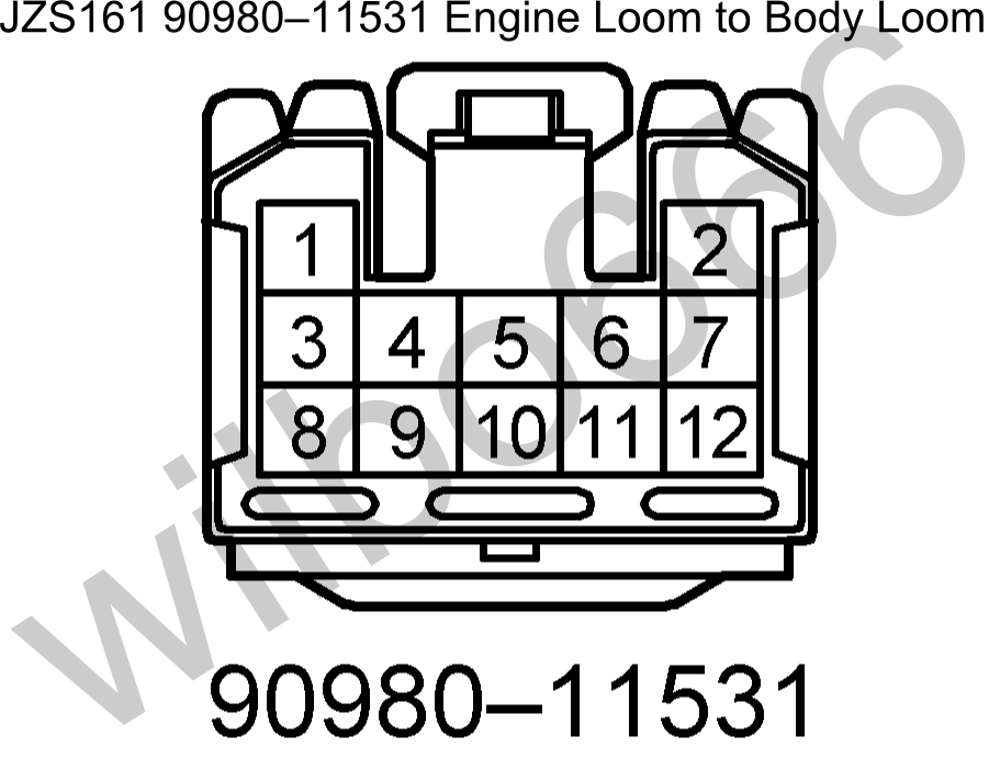
BF1 Plug - Configuration ( Pin Number , Symbol , Definition , Input or Output , Description )
Pin 1 - / / / / /
Pin 2 - Engine ECU: E2, Ambient Temperature Sensor Ground, Output, The body loom side of this pin connects to the ambient temperature sensor thermistor mounted at the far front of the car. The engine loom side of this pin connects to the engine ECU pin E2 to provide a ground for the ambient temperature sensor.
Pin 3 - Engine Mounted Diagnostic Connector: AB, SRS Airbag Power, Input, The body loom side of this pin connects to the SRS airbag control ECU AB pin. The engine loom side of this pin connects to the diagnostic connector mounted on the side of the engine. Note: Pre 2000-07 models only, later models do not have this pin wired.
Pin 4 - / / / /
Pin 5 - Engine Mounted Diagnostic Connector: TS 4WS ECU: TS, Test Enable, Input, The body loom side of this pin connects to a number of control module TS input pins. The engine loom side of this pin connects to the diagnostic connector mounted on the side of the engine.
Pin 6 - Engine ECU: R, Reverse Gear Automatic Transmission Position Switch Indicator, Output, The body loom side of this pin needs to be connected to the engine ECU R input pin and the reverse lights.
The engine loom side of this pin connects to automatic transmission shifter position switch mounted on the automatic transmission and outputs battery voltage when the automatic transmission shifter is in the R position.
Pin 7 - , Alternator Battery Voltage Sense, Input, The body loom side of this pin needs to be connected to the battery via a 5A fuse. The engine loom side of this pin connects to the alternator S pin.
Pin 8 - Proportional Power Steering ECU: SOL+, Proportional Power Steering Solenoid, Input, The body loom side of this pin connects to the proportional power steering ECU SOL+ pin. The engine loom side of this pin connects to the proportional power steering solenoid located on the power steering pump.
Pin 9 - Proportional Power Steering ECU: SOL-, Proportional Power Steering Solenoid, Input, The body loom side of this pin connects to the proportional power steering ECU SOL- pin. The engine loom side of this pin connects to the proportional power steering solenoid located on the power steering pump.
Pin 10 - Engine Mounted Diagnostic Connector: WA, ABS & VSC ECU: WA ABS, Input, The body loom side of this pin connects to the ABS control ECU WA pin and also the ABS light mounted in the dash. The engine loom side of this pin connects to the diagnostic connector mounted on the side of the engine. Note that there is a shorting link inserted between terminals WA and WB of the diagnostic connector.
Pin 11 - Engine Mounted Diagnostic Connector: WB, ABS & VSC ECU: WB ABS, Output, The body loom side of this pin connects to the ABS relay. The engine loom side of this pin connects to the diagnostic connector mounted on the side of the engine. Note that there is a shorting link inserted between terminals WA and WB of the diagnostic connector from factory.
Pin 12 - Engine Mounted Diagnostic Connector: TC / Engine ECU: TC / ABS & VSC ECU: TC / 4WS ECU: TC, Test Connector, Input, The body loom side of this pin connects to the TC pin on a number of control modules. The engine loom side of this pin connects to the diagnostic connector mounted on the side of the engine.

BF2 Plug - Configuration ( Pin Number , Symbol , Definition , Input or Output , Description )
Pin 1 - Engine ECU: ACMG, Air Conditioning Magnetic Clutch Relay Trigger Signal, Output, The body loom side of this pin needs to be connected to the AC magnetic clutch relay coil negative. The engine loom side of this pin connects to the engine ECU ACMG pin.
Pin 2 - Engine ECU: P, Park Gear Automatic Transmission Position Switch Indicator, Output, The body loom side of this pin needs to be connected to the engine ECU P input pin. The engine loom side of this pin connects to automatic transmission shifter position switch mounted on the automatic transmission and outputs battery voltage when the automatic transmission shifter is in the P position.
Pin 3 / / / /
Pin 4 / / / /
Pin 5 / / / /
Pin 6 - Power to Coils and Igniter, Input, The body loom side of this pin needs to be connected to battery voltage via the ignition switch when the ignition is in the RUN and CRANK positions to switch battery voltage to the coils and igniter. The engine loom side of this pin connects to the coil and igniter power supply pins.
Pin 7 - Power to Fuel Injectors, Input, The body loom side of this pin needs to be connected to battery voltage via the ignition switch when the ignition is in the RUN and CRANK positions to switch battery voltage to the fuel injectors. The engine loom side of this pin connects to the fuel injector power supply pins.
Pin 8 - Starter Motor Relay Switched Power, Input, The body loom side of this pin needs to be connected to the starter motor relay switched power output which switches battery voltage to the starter motor to turn it on. The engine loom side of this pin connects to the starter motor. The starter motor is grounded via the engine block. Refer to pins BF3-4 and BF3-5 for further information regarding the starter / starter relay circuit.
Pin 9 - Engine ECU: +B, +B2 Main EFI Relay Switched Power, Input, The body loom side of this pin needs to be connected to main EFI relay switched power output which switches battery voltage to the engine ECU, VSVs, etc. The main EFI relay is switched via the engine ECU M-REL output pin. The engine loom side of this pin connects to the engine ECU, VSVs, etc power supply pins.
Pin 10 / / / /

BF3 Plug - Configuration ( Pin Number , Symbol , Definition , Input or Output , Description )
Pin 1 / / / /
Pin 2 - Engine ECU: TACH, Engine Mounted Diagnostic Connector: IG-, Tachometer Output from Igniter, Output, The body loom side of this pin needs to be connected to the dash tachometer and other vehicle systems. The engine loom side of this pin connects to the engine ECU TACH pin which outputs a 0V to battery voltage signal that is related to engine RPM.
Pin 3 - Engine ECU: D, Drive Gear Automatic Transmission Position Switch Indicator, Output, The body loom side of this pin needs to be connected to the engine ECU D input pin. The engine loom side of this pin connects to automatic transmission shifter position switch mounted on the automatic transmission and outputs battery voltage when the automatic transmission shifter is in the D position.
Pin 4 - Engine ECU: STA Starter Motor Relay Trigger Signal, Output, The body loom side of this pin needs to be connected to the starter motor relay coil to turn it on when the ignition switch is in CRANK position and the automatic transmission park / neutral switch is closed - that is the automatic transmission selector is in the park / neutral position. The engine loom side of this pin is connected to the automatic transmission park / neutral position switch and also the engine ECU STA pin. Refer to pin BF3-5 for further information.
Pin 5 - Starter Signal, Input, The body loom side of this pin needs to be connected to battery voltage when the ignition switch is in CRANK position. The engine loom side of this pin connects to one side of the automatic transmission park / neutral switch to provide power to the automatic transmission shifter position switch. Refer to pin BF3-4 for further information.
Pin 6 / / / /
Pin 7 - Engine ECU: E1, Ground, Output, The body loom side of this pin connects to the ground for the cruise control switch assembly. The engine loom side of this pin connects to the engine ECU E1 pin which is Grounded at the intake manifold.
Pin 8 / / / /
Pin 9 - Ignition Switched Power, Input, The body loom side of this pin needs to be connected to ignition switched power source that supplies battery voltage when the ignition is in the RUN and CRANK Positions. The engine loom side of this pin connects switched battery voltage to the alternator, automatic transmission position switch and the reverse lights.
As I did on the other thread , I always started working on the connectors farthest to the ECU connectors . You will need to inspect connectors , pins & wires connectivity from end to end and extend what needs to be extended so the wiring harness will reach the passenger floorboard.
Here you have the farthest set of connectors

1) O2 Sensor

Pin 1 goes to Pin 4 of B2 Plug
Pin 2 goes to Pin 9 of BF2 and to the Diagnostic Port (B+ voltage supply) (should go to ( SC3 IJ1-5 , SC4 EB2-3 , MK4 ))
Pin 3 goes to Pin 12 of B2 Plug
Pin 4 goes to Pin 17 of B2 Plug and to the Ground connector on the intake manifold (E1 = ECU Ground)
2) MAF Sensor

Pin 1 goes to Pin 22 of B2 plug
Pin 2 goes to Pin 18 of B2 plug and to Pin 2 of BF1 plug (E2 = Sensor ground)
Pin 3 goes to Pin 19 of B2 plug
Pin 4 goes to Pin 9 of BF2 and to the Diagnostic Port and to Pin 2 of O2 Sensor (B+ voltage supply) (should go to ( SC3 IJ1-5 , SC4 EB2-3 , MK4 ))
Pin 5 goes to Pin 10 of B2 plug
3) Coolant Sensor

Pin 1 goes to Pin 18 of B2 plug and to Pin 2 of BF1 plug (E2 = Sensor ground)
Pin 2 goes to Pin 14 of B2 plug
Note : For our SCs and MKIVs , we will need to install another ONE Wire Coolant Gauge Sensor on the upper coolant elbow then add a wire that goes to one of the body plugs which we will do a bit later. There is already a threaded hole in that area. The Aristo / GS do not need it cause the dash gauge gets it coolant sensor value using the abovementioned Coolant Sensor through their Multiplex network.
4) Crank Position Sensor

Pin 1 goes to Pin 23 of B1 Plug
Pin 2 goes to Pin 22 of B1 Plug
5) VSVPMC ( Blue - Waste Gate Valve )

Pin 1 goes to Pin 9 of BF2 and to the Diagnostic Port (B+ voltage supply) (should go to ( SC3 IJ1-5 , SC4 EB2-3 , MK4 ))
Pin 2 goes to Pin 15 of B1 Plug
6) VSV2 ( Black - Exhaust Control Valve )

Pin 1 goes to Pin 9 of BF2 and to the Diagnostic Port (B+ voltage supply) (should go to ( SC3 IJ1-5 , SC4 EB2-3 , MK4 ))
Pin 2 goes to Pin 3 of B2 Plug
7) Water Temp Gauge Sender (as mentioned , need to add this one)
Pin 1 of the Water Temp Gauge Sender goes to a body plug (SC3 IK1-9 , SC4 IK1-9 & Short-3 , MK4 II1-19 )
8) Alternator Connector (The SC400 and some SC300 depending on year just like my Black Pearl will not have the alternator plug as part of the engine harness so you may take this out . In my case I will re-use one of the wire of this connector for the Water Temp Gauge Sender and the other two wires will be for future use like when I am going single , they can be used for the boost solenoid.)
Just so you know where the 3 wires for the alternator go to so you can label them either for future use or if you have an older model of SC300/SC400 whose alternator wires are part of the engine harness
Pin 1 goes to Pin 26 of B1
Pin 2 goes to Pin 9 of BF3
Pin 3 goes to Pin 7 of BF1 (on my harness , this wire goes to Pin 9 of IK1 for the Coolant Temp Sender for the Dash Board Gauge)

Diagram (can be zoomed through the + at Photobucket) to verify wiring for O2 sensor , MAF , VSV2 , VSVPMC, Crank Position Sensor, Coolant Sensor

Now you have seen the different plugs on that area of the harness and know where each pin should go , time to do The Drill (remember ??? .. from the other thread I told you to make sure you know ) .
For those who do not remember what is THE DRILL , let me remind you
A) Decide if you need the plug and wires depending on your particular setup .
..A1) IF YES ( that means you are keeping the plug ) , then
......A1a) Inspect the connector (plug) if it is physically damaged
......A1b) Replace that plug if its casing or lock is broken
......A1c) Go through all the wires of that plug
.........A1c1) Trace the wire by finding the pin from the plug where it goes to
............A1c11) If the wire ends at an ECU connector OR Other Plug (except BF1, BF2 & BF3 Plugs) then leave it where it is. That is where it should be anyway.
............A1c12) If the wire ends at any of the BF1,BF2 & BF3 Plugs then pull it out from there and label it..
.........A1c2) If the wire ends at an ECU connector OR BF1, BF2 & BF3 Plugs then EXTEND IT otherwise you are not extending the wire.
.........A1c3) Heat Shrink Wrap those solder points ( make sure no strand of wire is out of that heat shrink )
.........A1c4) Check connectivity between the two end points for that particular wire which you have just extended.
......A1d) Cover the wires of the plug with electrical tape and corrugated flexible hose once you are done with every single wire on that plug.
...A2) IF NO ( that means you are NOT keeping the plug ) and YOU ARE NOT KEEPING THE WIRES for future needs then start pulling the plug and its wires out
...A3) IF NO ( that means you are NOT keeping the plug ) BUT YOU ARE KEEPING THOSE WIRES for other components
......A3a) Remove the stock connector
......A3b) Extend the wires you are keeping and pull out the wires you do not need.
......A3c) Heat Shrink Wrap those solder points ( make sure no strand of wire is out of that heat shrink )
......A3d) Check connectivity between the two end points for that particular wire which you have just extended.
......A3e) Label the wire on both ends so you know it is an extra wire and which end point goes to the other end point
B) As mentioned .. you can do the CHART for reference, troubleshooting and re-checking purposes .
Last night, I started cleaning up my 2jzgte VVTi swap harness. Removing all the wrappings


I would use quite a different approach now in extending the wires which I didn't do on the other thread. To save on the amount of soldering I need to do , I will use two vvti harnesses. Usually you will cut a wire then insert the length of wire you need and then you will have two solder points on that particular wire .
What I will do is use two VVTi harnesses since I have an extra one. That will also save me from buying pins for the F59 and F60 plugs which I would pickup from the dealership in a bit since I pre-ordered them yesterday. Using two vvti harnesses will enable me to have only one solder point on each wire . Cut one harness near the plugs , get the extension wires (with desired length) and plugs from the other harness and then merging (soldering) the two , thereby having only one solder point in every wire
. It will save a lot of time and some money of course.

So how long should your extension be ? On a VVTi harness , if you measure from the end of the Intake Plenum , the wire to the ECU on the floor board would be around 58" . It is safer to have it a bit longer than being short. In the following picture , it is where those wires bend (end of rubber wrap) which is the end of the intake plenum and just right there on the firewall. .. that is where you start measuring 58"

Before I continue on the harness, since the harness will be affected , I want to remind you guys that when you install a stock 2jzgte VVTi on your SC or MKIV , there are parts you need to replace ... aside from the usual like front to rear sump and other maintenance parts , you will need to replace your PS pump and AC compressor . The VVTi versions has some wirings/plugs there you won't need . So get the Supra or SC PS pump and AC compressor .
Picked up the F59 and F60 connector from the dealership which were $20 for both . Pins / lead wires I will get from the extra VVTi harness . All Pins for those F59 & F60 plugs are same as with that of the B1 , B2 & B3 plugs.


.
Let me introduce you to the other plugs on the 2jzgte VVTi Aristo harness that we will not need but some of its wires we will need and pin them to our SC / MKIV body plugs or ECU plugs.
BF1 , BF2 and BF3 plugs found on the lower part of this picture . You already know that the ones on top are the B1, B2 and B3 ECU plugs .

Just for you to know what the wires on those plugs do , here is a summary . AGAIN WE WILL NOT USE THESE PLUGS. In fact there will be some wires / pins you don't need to re pin but just take them out cause you will not be needing depending on what you want to include on your harness or not .

BF1 Plug - Configuration ( Pin Number , Symbol , Definition , Input or Output , Description )
Pin 1 - / / / / /
Pin 2 - Engine ECU: E2, Ambient Temperature Sensor Ground, Output, The body loom side of this pin connects to the ambient temperature sensor thermistor mounted at the far front of the car. The engine loom side of this pin connects to the engine ECU pin E2 to provide a ground for the ambient temperature sensor.
Pin 3 - Engine Mounted Diagnostic Connector: AB, SRS Airbag Power, Input, The body loom side of this pin connects to the SRS airbag control ECU AB pin. The engine loom side of this pin connects to the diagnostic connector mounted on the side of the engine. Note: Pre 2000-07 models only, later models do not have this pin wired.
Pin 4 - / / / /
Pin 5 - Engine Mounted Diagnostic Connector: TS 4WS ECU: TS, Test Enable, Input, The body loom side of this pin connects to a number of control module TS input pins. The engine loom side of this pin connects to the diagnostic connector mounted on the side of the engine.
Pin 6 - Engine ECU: R, Reverse Gear Automatic Transmission Position Switch Indicator, Output, The body loom side of this pin needs to be connected to the engine ECU R input pin and the reverse lights.
The engine loom side of this pin connects to automatic transmission shifter position switch mounted on the automatic transmission and outputs battery voltage when the automatic transmission shifter is in the R position.
Pin 7 - , Alternator Battery Voltage Sense, Input, The body loom side of this pin needs to be connected to the battery via a 5A fuse. The engine loom side of this pin connects to the alternator S pin.
Pin 8 - Proportional Power Steering ECU: SOL+, Proportional Power Steering Solenoid, Input, The body loom side of this pin connects to the proportional power steering ECU SOL+ pin. The engine loom side of this pin connects to the proportional power steering solenoid located on the power steering pump.
Pin 9 - Proportional Power Steering ECU: SOL-, Proportional Power Steering Solenoid, Input, The body loom side of this pin connects to the proportional power steering ECU SOL- pin. The engine loom side of this pin connects to the proportional power steering solenoid located on the power steering pump.
Pin 10 - Engine Mounted Diagnostic Connector: WA, ABS & VSC ECU: WA ABS, Input, The body loom side of this pin connects to the ABS control ECU WA pin and also the ABS light mounted in the dash. The engine loom side of this pin connects to the diagnostic connector mounted on the side of the engine. Note that there is a shorting link inserted between terminals WA and WB of the diagnostic connector.
Pin 11 - Engine Mounted Diagnostic Connector: WB, ABS & VSC ECU: WB ABS, Output, The body loom side of this pin connects to the ABS relay. The engine loom side of this pin connects to the diagnostic connector mounted on the side of the engine. Note that there is a shorting link inserted between terminals WA and WB of the diagnostic connector from factory.
Pin 12 - Engine Mounted Diagnostic Connector: TC / Engine ECU: TC / ABS & VSC ECU: TC / 4WS ECU: TC, Test Connector, Input, The body loom side of this pin connects to the TC pin on a number of control modules. The engine loom side of this pin connects to the diagnostic connector mounted on the side of the engine.

BF2 Plug - Configuration ( Pin Number , Symbol , Definition , Input or Output , Description )
Pin 1 - Engine ECU: ACMG, Air Conditioning Magnetic Clutch Relay Trigger Signal, Output, The body loom side of this pin needs to be connected to the AC magnetic clutch relay coil negative. The engine loom side of this pin connects to the engine ECU ACMG pin.
Pin 2 - Engine ECU: P, Park Gear Automatic Transmission Position Switch Indicator, Output, The body loom side of this pin needs to be connected to the engine ECU P input pin. The engine loom side of this pin connects to automatic transmission shifter position switch mounted on the automatic transmission and outputs battery voltage when the automatic transmission shifter is in the P position.
Pin 3 / / / /
Pin 4 / / / /
Pin 5 / / / /
Pin 6 - Power to Coils and Igniter, Input, The body loom side of this pin needs to be connected to battery voltage via the ignition switch when the ignition is in the RUN and CRANK positions to switch battery voltage to the coils and igniter. The engine loom side of this pin connects to the coil and igniter power supply pins.
Pin 7 - Power to Fuel Injectors, Input, The body loom side of this pin needs to be connected to battery voltage via the ignition switch when the ignition is in the RUN and CRANK positions to switch battery voltage to the fuel injectors. The engine loom side of this pin connects to the fuel injector power supply pins.
Pin 8 - Starter Motor Relay Switched Power, Input, The body loom side of this pin needs to be connected to the starter motor relay switched power output which switches battery voltage to the starter motor to turn it on. The engine loom side of this pin connects to the starter motor. The starter motor is grounded via the engine block. Refer to pins BF3-4 and BF3-5 for further information regarding the starter / starter relay circuit.
Pin 9 - Engine ECU: +B, +B2 Main EFI Relay Switched Power, Input, The body loom side of this pin needs to be connected to main EFI relay switched power output which switches battery voltage to the engine ECU, VSVs, etc. The main EFI relay is switched via the engine ECU M-REL output pin. The engine loom side of this pin connects to the engine ECU, VSVs, etc power supply pins.
Pin 10 / / / /

BF3 Plug - Configuration ( Pin Number , Symbol , Definition , Input or Output , Description )
Pin 1 / / / /
Pin 2 - Engine ECU: TACH, Engine Mounted Diagnostic Connector: IG-, Tachometer Output from Igniter, Output, The body loom side of this pin needs to be connected to the dash tachometer and other vehicle systems. The engine loom side of this pin connects to the engine ECU TACH pin which outputs a 0V to battery voltage signal that is related to engine RPM.
Pin 3 - Engine ECU: D, Drive Gear Automatic Transmission Position Switch Indicator, Output, The body loom side of this pin needs to be connected to the engine ECU D input pin. The engine loom side of this pin connects to automatic transmission shifter position switch mounted on the automatic transmission and outputs battery voltage when the automatic transmission shifter is in the D position.
Pin 4 - Engine ECU: STA Starter Motor Relay Trigger Signal, Output, The body loom side of this pin needs to be connected to the starter motor relay coil to turn it on when the ignition switch is in CRANK position and the automatic transmission park / neutral switch is closed - that is the automatic transmission selector is in the park / neutral position. The engine loom side of this pin is connected to the automatic transmission park / neutral position switch and also the engine ECU STA pin. Refer to pin BF3-5 for further information.
Pin 5 - Starter Signal, Input, The body loom side of this pin needs to be connected to battery voltage when the ignition switch is in CRANK position. The engine loom side of this pin connects to one side of the automatic transmission park / neutral switch to provide power to the automatic transmission shifter position switch. Refer to pin BF3-4 for further information.
Pin 6 / / / /
Pin 7 - Engine ECU: E1, Ground, Output, The body loom side of this pin connects to the ground for the cruise control switch assembly. The engine loom side of this pin connects to the engine ECU E1 pin which is Grounded at the intake manifold.
Pin 8 / / / /
Pin 9 - Ignition Switched Power, Input, The body loom side of this pin needs to be connected to ignition switched power source that supplies battery voltage when the ignition is in the RUN and CRANK Positions. The engine loom side of this pin connects switched battery voltage to the alternator, automatic transmission position switch and the reverse lights.
As I did on the other thread , I always started working on the connectors farthest to the ECU connectors . You will need to inspect connectors , pins & wires connectivity from end to end and extend what needs to be extended so the wiring harness will reach the passenger floorboard.
Here you have the farthest set of connectors

1) O2 Sensor

Pin 1 goes to Pin 4 of B2 Plug
Pin 2 goes to Pin 9 of BF2 and to the Diagnostic Port (B+ voltage supply) (should go to ( SC3 IJ1-5 , SC4 EB2-3 , MK4 ))
Pin 3 goes to Pin 12 of B2 Plug
Pin 4 goes to Pin 17 of B2 Plug and to the Ground connector on the intake manifold (E1 = ECU Ground)
2) MAF Sensor

Pin 1 goes to Pin 22 of B2 plug
Pin 2 goes to Pin 18 of B2 plug and to Pin 2 of BF1 plug (E2 = Sensor ground)
Pin 3 goes to Pin 19 of B2 plug
Pin 4 goes to Pin 9 of BF2 and to the Diagnostic Port and to Pin 2 of O2 Sensor (B+ voltage supply) (should go to ( SC3 IJ1-5 , SC4 EB2-3 , MK4 ))
Pin 5 goes to Pin 10 of B2 plug
3) Coolant Sensor

Pin 1 goes to Pin 18 of B2 plug and to Pin 2 of BF1 plug (E2 = Sensor ground)
Pin 2 goes to Pin 14 of B2 plug
Note : For our SCs and MKIVs , we will need to install another ONE Wire Coolant Gauge Sensor on the upper coolant elbow then add a wire that goes to one of the body plugs which we will do a bit later. There is already a threaded hole in that area. The Aristo / GS do not need it cause the dash gauge gets it coolant sensor value using the abovementioned Coolant Sensor through their Multiplex network.
4) Crank Position Sensor

Pin 1 goes to Pin 23 of B1 Plug
Pin 2 goes to Pin 22 of B1 Plug
5) VSVPMC ( Blue - Waste Gate Valve )

Pin 1 goes to Pin 9 of BF2 and to the Diagnostic Port (B+ voltage supply) (should go to ( SC3 IJ1-5 , SC4 EB2-3 , MK4 ))
Pin 2 goes to Pin 15 of B1 Plug
6) VSV2 ( Black - Exhaust Control Valve )

Pin 1 goes to Pin 9 of BF2 and to the Diagnostic Port (B+ voltage supply) (should go to ( SC3 IJ1-5 , SC4 EB2-3 , MK4 ))
Pin 2 goes to Pin 3 of B2 Plug
7) Water Temp Gauge Sender (as mentioned , need to add this one)
Pin 1 of the Water Temp Gauge Sender goes to a body plug (SC3 IK1-9 , SC4 IK1-9 & Short-3 , MK4 II1-19 )
8) Alternator Connector (The SC400 and some SC300 depending on year just like my Black Pearl will not have the alternator plug as part of the engine harness so you may take this out . In my case I will re-use one of the wire of this connector for the Water Temp Gauge Sender and the other two wires will be for future use like when I am going single , they can be used for the boost solenoid.)
Just so you know where the 3 wires for the alternator go to so you can label them either for future use or if you have an older model of SC300/SC400 whose alternator wires are part of the engine harness
Pin 1 goes to Pin 26 of B1
Pin 2 goes to Pin 9 of BF3
Pin 3 goes to Pin 7 of BF1 (on my harness , this wire goes to Pin 9 of IK1 for the Coolant Temp Sender for the Dash Board Gauge)

Diagram (can be zoomed through the + at Photobucket) to verify wiring for O2 sensor , MAF , VSV2 , VSVPMC, Crank Position Sensor, Coolant Sensor

Now you have seen the different plugs on that area of the harness and know where each pin should go , time to do The Drill (remember ??? .. from the other thread I told you to make sure you know ) .
For those who do not remember what is THE DRILL , let me remind you
A) Decide if you need the plug and wires depending on your particular setup .
..A1) IF YES ( that means you are keeping the plug ) , then
......A1a) Inspect the connector (plug) if it is physically damaged
......A1b) Replace that plug if its casing or lock is broken
......A1c) Go through all the wires of that plug
.........A1c1) Trace the wire by finding the pin from the plug where it goes to
............A1c11) If the wire ends at an ECU connector OR Other Plug (except BF1, BF2 & BF3 Plugs) then leave it where it is. That is where it should be anyway.
............A1c12) If the wire ends at any of the BF1,BF2 & BF3 Plugs then pull it out from there and label it..
.........A1c2) If the wire ends at an ECU connector OR BF1, BF2 & BF3 Plugs then EXTEND IT otherwise you are not extending the wire.
.........A1c3) Heat Shrink Wrap those solder points ( make sure no strand of wire is out of that heat shrink )
.........A1c4) Check connectivity between the two end points for that particular wire which you have just extended.
......A1d) Cover the wires of the plug with electrical tape and corrugated flexible hose once you are done with every single wire on that plug.
...A2) IF NO ( that means you are NOT keeping the plug ) and YOU ARE NOT KEEPING THE WIRES for future needs then start pulling the plug and its wires out
...A3) IF NO ( that means you are NOT keeping the plug ) BUT YOU ARE KEEPING THOSE WIRES for other components
......A3a) Remove the stock connector
......A3b) Extend the wires you are keeping and pull out the wires you do not need.
......A3c) Heat Shrink Wrap those solder points ( make sure no strand of wire is out of that heat shrink )
......A3d) Check connectivity between the two end points for that particular wire which you have just extended.
......A3e) Label the wire on both ends so you know it is an extra wire and which end point goes to the other end point
B) As mentioned .. you can do the CHART for reference, troubleshooting and re-checking purposes .
Last edited by gerrb; 01-10-16 at 02:41 PM.
12-21-15, 03:48 PM
#3404
By now you should be working on the connectors we have just discussed above .... inspecting the physical condition of the connectors , extending their wires and checking connectivity from end to end .
To make it more clear how you can end up with lesser solder points by using 2 x 2jzgte vvti wiring harness . Let me show you some pictures ..
Let us take the example of Pin 1 of the Oxygen sensor ...
You cut the wire on the harness you are working on

Take note that as I mentioned , the length you need from the end of the intake manifold near the firewall to the ECU would be around 58" . (that will be near that corner where the rubber wrap is)

Cut the wire you need near the O2 sensor from the other harness , measure a length to complete the 58" you need then solder that to the one you just cut on the harness you are working on . Thus you are actually using the extended wire and plugs of the other harness. On the bottom of the picture , eventually those ecu plugs will all not be used since you are cutting their wires one by one. They will be replaced by the ecu plugs on top of the picture.

So instead of cutting the wire , then inserting the length of wire you need , then having to solder two points on the wire, now you are only soldering a single point on the wire . A bit tricky but less solder points better. There will be less solder points that can go bad. Of course if you just want to insert the length of wire and solder two points , that is fine. I am just giving you an alternative here if you have 2 vvti 2jzgte harness
Here you can see 3 wires from the O2 sensor had been extended .. out from the old ECU connectors on the left into the new ECU connectors on the right. One solder point per wire.

Just to give you an idea of how my harness looks like after I was done with the first set of connectors mentioned on the previous posts .. inspected, checked and wrapped . Black Pearl is a 1997 whose alternator connector is incorporated with the chassis wiring so it is not part of the engine harness. So what I did , I just cut the wires of the alternator connector which you see right on the picture . One of them I will use for the dash temperature gauge sensor and the rest will be extra for future needs. For those who have an SC or MKIV whose alternator wirings are part of the engine harness , you can check out my other harness thread where that connector is incorporated and follow the wirings there.

the wires of the connectors above extended too. As you know I took quite an unconventional way here to save on the number of solder points...

Last edited by gerrb; 01-10-16 at 02:28 PM.
