
2jzGTE SCs - The Siblings of my Supra MKIV Toys


 12-23-15, 03:08 PM
#3407
Coils 1, 2 & 3 and VSVs 1 & 2 (watch the coil numbering and where they go on the igniter... labeling is quite confusing so I described their locations too)
<a>href="http://s1010.photobucket.com/user/gerrb/media/4thSCBlackMamba/20151230_193444_zpsvn3rljc0.jpg.html" target="_blank"><img>src="http://i1010.photobucket.com/albums/af227/gerrb/4thSCBlackMamba/20151230_193444_zpsvn3rljc0.jpg" border="0" alt=" photo 20151230_193444_zpsvn3rljc0.jpg"/></a>
Coil 3 (Back of Engine)
Pin 1 goes to Pin 6 of BF2 (should go to ( SC3 IJ1-3 , SC4 IJ1-3 , MK4 ))
Pin 2 goes to Pin 10 of Igniter (C1-)
Coil 2 (Middle)
Pin 1 goes to Pin 6 of BF2 (should go to ( SC3 IJ1-3 , SC4 IJ1-3 , MK4 ))
Pin 2 goes to Pin 2 of Igniter (C3-)
Coil 1 (front of Engine)
Pin 1 goes to Pin 6 of BF2 (should go to ( SC3 IJ1-3 , SC4 IJ1-3 , MK4 ))
Pin 2 goes to Pin 1 of Igniter (C2-)
VSV1 (Black Connector)
Pin 1 goes to Pin 9 of BF2 and to the Diagnostic Port (B+ voltage supply) (B+ voltage supply) (should go to ( SC3 IJ1-5 , SC4 EB2-3 , MK4 ))
Pin 2 goes to Pin 5 of B1
VSV3 (Blue Connector)
Pin 1 goes to Pin 9 of BF2 and to the Diagnostic Port (B+ voltage supply) (B+ voltage supply) (should go to ( SC3 IJ1-5 , SC4 EB2-3 , MK4 ))
Pin 2 goes to Pin 12 of B3
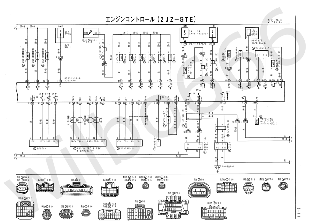
Diagram (can be zoomed through the + at Photobucket) to verify Wiring for Coils 1 , 2 & 3

Diagram (can be zoomed through the + at Photobucket) to verify wiring for VSV 1 & 2

<a>href="http://s1010.photobucket.com/user/gerrb/media/4thSCBlackMamba/20151230_193444_zpsvn3rljc0.jpg.html" target="_blank"><img>src="http://i1010.photobucket.com/albums/af227/gerrb/4thSCBlackMamba/20151230_193444_zpsvn3rljc0.jpg" border="0" alt=" photo 20151230_193444_zpsvn3rljc0.jpg"/></a>
Coil 3 (Back of Engine)
Pin 1 goes to Pin 6 of BF2 (should go to ( SC3 IJ1-3 , SC4 IJ1-3 , MK4 ))
Pin 2 goes to Pin 10 of Igniter (C1-)
Coil 2 (Middle)
Pin 1 goes to Pin 6 of BF2 (should go to ( SC3 IJ1-3 , SC4 IJ1-3 , MK4 ))
Pin 2 goes to Pin 2 of Igniter (C3-)
Coil 1 (front of Engine)
Pin 1 goes to Pin 6 of BF2 (should go to ( SC3 IJ1-3 , SC4 IJ1-3 , MK4 ))
Pin 2 goes to Pin 1 of Igniter (C2-)
VSV1 (Black Connector)
Pin 1 goes to Pin 9 of BF2 and to the Diagnostic Port (B+ voltage supply) (B+ voltage supply) (should go to ( SC3 IJ1-5 , SC4 EB2-3 , MK4 ))
Pin 2 goes to Pin 5 of B1
VSV3 (Blue Connector)
Pin 1 goes to Pin 9 of BF2 and to the Diagnostic Port (B+ voltage supply) (B+ voltage supply) (should go to ( SC3 IJ1-5 , SC4 EB2-3 , MK4 ))
Pin 2 goes to Pin 12 of B3
Diagram (can be zoomed through the + at Photobucket) to verify Wiring for Coils 1 , 2 & 3

Diagram (can be zoomed through the + at Photobucket) to verify wiring for VSV 1 & 2

Last edited by gerrb; 08-11-17 at 04:08 AM.
12-26-15, 03:23 PM
#3408
Before I went for the holidays to our place in the South , I did take out the PT-6870 from the Old Man's Tan , my new daily driver at 1050rwhp. I wanted to see how the Borg Warner 72mm FMW (Billet) SFWD Class limit turbo will do with an SP Quick Spool Valve so I did install them and be back to the dyno soon. Just curious what the power band would be since the 72mm has a bigger A/R. The VE of this engine is much more than what the 6870 can handle since it has a ported head with +1 Ferrea Valves. I believe power would be same for both turbos at the same boost level but the 72mm will hold power up top stronger. Looks like I had been reaching the compressor wheel flow limit already of the PT-6870 that is why I am trying this 72mm with a bigger A/R. But the transient response of the PT-6870 as always had been great. Spool was quick which was almost of no difference with the 67mm I had on the other SC.


Last edited by gerrb; 12-27-15 at 09:10 AM.
12-27-15, 08:54 AM
#3409
Someone asked me if the SP Quick Spool Valve is plug & play and its benefit. More often than not , it is not plug & play. You will need to do some grinding just to make sure there are no binding when that flap of the QSV moves to closed or open position. At lower RPMs, it actually diverts all the exhaust energy to half part of the turbine. Thus effectively lowering your A/R size like to 50% of turbine size so you get better spool. Then at past a certain boost like 11psi , you can fully open the qsv so you can get the power at the top end utilizing the full size of your turbine housing. That is the thing , higher hp turbos will always have bigger turbine housing thus can be laggy. That is where the QSV can help.
On my end I had to grind a part of the Turbine Exhaust Housing

Got to remove the pin and its lock ( top most part of picture ) .. just to test the flap's movement .. there should be no binding at all


On my end I had to grind a part of the Turbine Exhaust Housing

Got to remove the pin and its lock ( top most part of picture ) .. just to test the flap's movement .. there should be no binding at all


Last edited by gerrb; 12-28-15 at 06:07 AM.
01-04-16, 09:04 AM
#3410
Need to move my *** today. Holidays are over and the Black Pearl is long overdue to have been running as I have planned. I got to finish cleaning up and extending the 2jzgte VVTi Aristo harness then by next two days I can move wires from the BF1, BF2,BF3 to their corresponding wires into the SC300 body plugs, merge all the wires / plugs I need from the SC300 and wire up the F59 and F60 plugs of the ECU. Then install the harness into the engine bay and wrap up the small things on the car so I can get it started and running.
Next farthest plug is #1 injector plug , so I might as well work on all the injector plugs and plugs on that area .


Injector #1
Pin 1 goes to Pin 5 of B2
Pin 2 goes to Pin 7 of BF2 (should go to ( SC3 IJ1-7 , SC4 IJ1-7 , MK4 ))
Injector #2
Pin 1 goes to Pin 6 of B2
Pin 2 goes to Pin 7 of BF2 (should go to ( SC3 IJ1-7 , SC4 IJ1-7 , MK4 ))
Injector #3
Pin 1 goes to Pin 1 of B1
Pin 2 goes to Pin 7 of BF2 (should go to ( SC3 IJ1-7 , SC4 IJ1-7 , MK4 ))
Injector #4
Pin 1 goes to Pin 2 of B1
Pin 2 goes to Pin 7 of BF2 (should go to ( SC3 IJ1-7 , SC4 IJ1-7 , MK4 ))
Injector #5
Pin 1 goes to Pin 3 of B1
Pin 2 goes to Pin 7 of BF2 (should go to ( SC3 IJ1-7 , SC4 IJ1-7 , MK4 ))
Injector #6
Pin 1 goes to Pin 4 of B1
Pin 2 goes to Pin 7 of BF2 (should go to ( SC3 IJ1-7 , SC4 IJ1-7 , MK4 ))
Accelerator Pedal Position Sensor
Pin 1 goes to Pin 16 of B2
Pin 2 goes to Pin 15 of B2
Pin 3 goes to Pin 2 of BF1 and Pin 18 of B2 (sensor ground)
Pin 4 goes to Pin 2 of B2 (sensor B+ voltage)
Map Sensor
Pin 1 goes to Pin 2 of BF1 and Pin 18 of B2 (sensor ground)
Pin 2 goes to Pin 9 of B2 (Map Input)
Pin 3 goes to Pin 2 of B2 (sensor B+ voltage)
VSVPRG (Black)
Pin 1 goes to Pin 9 of BF2 and to the Diagnostic Port (B+ voltage supply) (should go to ( SC3 IJ1-5 , SC4 EB2-3 , MK4 ))
Pin 2 goes to Pin 7 of B2
VSVFPU (Blue)
Pin 1 goes to Pin 9 of BF2 and to the Diagnostic Port (B+ voltage supply) (should go to ( SC3 IJ1-5 , SC4 EB2-3 , MK4 ))
Pin 2 goes to Pin 16 of B3
Camshaft Sensor
Pin 1 goes to Pin 10 of B1
Pin 2 goes to Pin 22 of B1
Diagram (can be zoomed through the + at Photobucket) to verify wiring for all the injectors

Diagram (can be zoomed through the + at Photobucket) to verify wiring for the Accelerator Pedal Position Sensor, Map Sensor, VSVPRG , VSVFPU, Camshaft Sensor

Next set of connectors are the Throttle Position Sensor, VVTi Solenoid Sensor


Throttle Position Sensor
Pin 1 goes Pin 2 of B2 (sensor B+ voltage)
Pin 2 goes to Pin 23 of B2
Pin 3 goes to Pin 24 of B2
Pin 4 goes to Pin 2 of BF1 and Pin 18 of B2 (sensor ground)
VVTi Solenoid
Pin 1 goes to Pin 18 of B1 OCV+
Pin 2 goes to Pin 17 of B1 OCV-
Electronic Throttle Control Clutch (ETCS-i)
Pin 1 goes to Pin 7 of B1
Pin 2 goes to Pin 8 of B1
Pin 3 goes to Pin 20 of B1
Pin 4 goes to Pin 19 of B1
Diagram (can be zoomed through the + at Photobucket) to verify wiring for the Throttle Position Sensor
Diagram (can be zoomed through the + at Photobucket) to verify wiring for the VVTi Solenoid, ETCS-i Cluth
Next set of connectors are the knock sensors, AC connector, intake grounds , starter, Oil Pressure , Oil Level, Power Steering and Igniter (Igniter is not anymore in the picture since I am moving it inside the car)

Knock Sensor 1
Pin 1 goes to Pin 28 of B1
Knock Sensor 2
Pin 1 goes to Pin 27 of B1
Igniter
Pin 1 goes to Pin 2 of Coil 1 (front of engine)
Pin 2 goes to Pin 2 of Coil 2 (middle coil)
Pin 3 goes to Front Intake Ground
Pin 4 goes to Pin 25 of B1
Pin 5 goes to Pin 13 of B1
Pin 6 goes to Pin 12 of B1
Pin 7 goes to Pin 11 of B1
Pin 8 goes to (This was empty in my 2jzgte VVTi Harness but should go to Pin 2 of BF3 . I filled it with a pin / wire and now goes to Pin 8 of IK1)
Pin 9 goes to Pin 6 of BF2 (should go to ( SC3 IJ1-3 , SC4 IJ1-3 , MK4 ))
Pin 10 goes to Pin 2 of Coil 3 (back of engine)
Starter Solenoid Connector
Pin 1 goes to Pin 8 of BF2 (should go to ( SC3 EB2-1 , SC4 EB2-1 , MK4 ))
Main Oil Level Switch (You will need to replace this connector with that of the SC or MKIV , the aristo vvti has a different connector)
Pin 1 goes to Pin 6 of B1 (should go to ( SC3 Ik1-23 , SC4 IK1-23 , MK4 ))
Pin 2 goes to Front Intake Ground
Main Oil Pressure Switch
Pin 1 goes to Pin 8 of B2 (should go to ( SC3 Ik1-20 , SC4 IK1-20 , MK4 ))
Proportional Power Steering ECU (PPS)
Pin 1 goes to Pin 8 of BF1 (should go to ( SC3 IJ2-6 , SC4 IJ2-6 , MK4 ))
Pin 2 goes to Pin 9 of BF1 (should go to ( SC3 IJ2-16 , SC4 IJ2-16 , MK4 ))
AC Compressor (You will need to replace the Aristo 3 pin connector with that of the 4 pin SC or MKIV , the aristo vvti has a different connector)
Pin 1 goes to Pin 29 of B1 (should go to ( SC3 II1-1 & EB1-7 , SC4 II1-1 & EB1-7 , MK4 ))
Pin 2 goes to Ground Intake Manifold (should go to ( SC3 II1-4 , SC4 II1-4 , MK4 ))
Pin 3 goes to Pin 1 of BF2 (should be ( SC3 empty , SC4 empty , MK4 ))
Pin 4 doesn't exist on the 3 pin Aristo vvti connector (on the SC / MKIV 4 pin connector this pin should go to ( SC3 EB1-1 , SC4 EB1-1 , MK4 ))
Diagram (can be zoomed through the + at Photobucket) to verify wiring for the Knock Sensors, Oil Level and Oil Pressure Switch
Diagram (can be zoomed through the + at Photobucket) to verify Wiring for Igniter

Next farthest plug is #1 injector plug , so I might as well work on all the injector plugs and plugs on that area .


Injector #1
Pin 1 goes to Pin 5 of B2
Pin 2 goes to Pin 7 of BF2 (should go to ( SC3 IJ1-7 , SC4 IJ1-7 , MK4 ))
Injector #2
Pin 1 goes to Pin 6 of B2
Pin 2 goes to Pin 7 of BF2 (should go to ( SC3 IJ1-7 , SC4 IJ1-7 , MK4 ))
Injector #3
Pin 1 goes to Pin 1 of B1
Pin 2 goes to Pin 7 of BF2 (should go to ( SC3 IJ1-7 , SC4 IJ1-7 , MK4 ))
Injector #4
Pin 1 goes to Pin 2 of B1
Pin 2 goes to Pin 7 of BF2 (should go to ( SC3 IJ1-7 , SC4 IJ1-7 , MK4 ))
Injector #5
Pin 1 goes to Pin 3 of B1
Pin 2 goes to Pin 7 of BF2 (should go to ( SC3 IJ1-7 , SC4 IJ1-7 , MK4 ))
Injector #6
Pin 1 goes to Pin 4 of B1
Pin 2 goes to Pin 7 of BF2 (should go to ( SC3 IJ1-7 , SC4 IJ1-7 , MK4 ))
Accelerator Pedal Position Sensor
Pin 1 goes to Pin 16 of B2
Pin 2 goes to Pin 15 of B2
Pin 3 goes to Pin 2 of BF1 and Pin 18 of B2 (sensor ground)
Pin 4 goes to Pin 2 of B2 (sensor B+ voltage)
Map Sensor
Pin 1 goes to Pin 2 of BF1 and Pin 18 of B2 (sensor ground)
Pin 2 goes to Pin 9 of B2 (Map Input)
Pin 3 goes to Pin 2 of B2 (sensor B+ voltage)
VSVPRG (Black)
Pin 1 goes to Pin 9 of BF2 and to the Diagnostic Port (B+ voltage supply) (should go to ( SC3 IJ1-5 , SC4 EB2-3 , MK4 ))
Pin 2 goes to Pin 7 of B2
VSVFPU (Blue)
Pin 1 goes to Pin 9 of BF2 and to the Diagnostic Port (B+ voltage supply) (should go to ( SC3 IJ1-5 , SC4 EB2-3 , MK4 ))
Pin 2 goes to Pin 16 of B3
Camshaft Sensor
Pin 1 goes to Pin 10 of B1
Pin 2 goes to Pin 22 of B1
Diagram (can be zoomed through the + at Photobucket) to verify wiring for all the injectors
Diagram (can be zoomed through the + at Photobucket) to verify wiring for the Accelerator Pedal Position Sensor, Map Sensor, VSVPRG , VSVFPU, Camshaft Sensor

Next set of connectors are the Throttle Position Sensor, VVTi Solenoid Sensor


Throttle Position Sensor
Pin 1 goes Pin 2 of B2 (sensor B+ voltage)
Pin 2 goes to Pin 23 of B2
Pin 3 goes to Pin 24 of B2
Pin 4 goes to Pin 2 of BF1 and Pin 18 of B2 (sensor ground)
VVTi Solenoid
Pin 1 goes to Pin 18 of B1 OCV+
Pin 2 goes to Pin 17 of B1 OCV-
Electronic Throttle Control Clutch (ETCS-i)
Pin 1 goes to Pin 7 of B1
Pin 2 goes to Pin 8 of B1
Pin 3 goes to Pin 20 of B1
Pin 4 goes to Pin 19 of B1
Diagram (can be zoomed through the + at Photobucket) to verify wiring for the Throttle Position Sensor
Diagram (can be zoomed through the + at Photobucket) to verify wiring for the VVTi Solenoid, ETCS-i Cluth

Next set of connectors are the knock sensors, AC connector, intake grounds , starter, Oil Pressure , Oil Level, Power Steering and Igniter (Igniter is not anymore in the picture since I am moving it inside the car)

Knock Sensor 1
Pin 1 goes to Pin 28 of B1
Knock Sensor 2
Pin 1 goes to Pin 27 of B1
Igniter
Pin 1 goes to Pin 2 of Coil 1 (front of engine)
Pin 2 goes to Pin 2 of Coil 2 (middle coil)
Pin 3 goes to Front Intake Ground
Pin 4 goes to Pin 25 of B1
Pin 5 goes to Pin 13 of B1
Pin 6 goes to Pin 12 of B1
Pin 7 goes to Pin 11 of B1
Pin 8 goes to (This was empty in my 2jzgte VVTi Harness but should go to Pin 2 of BF3 . I filled it with a pin / wire and now goes to Pin 8 of IK1)
Pin 9 goes to Pin 6 of BF2 (should go to ( SC3 IJ1-3 , SC4 IJ1-3 , MK4 ))
Pin 10 goes to Pin 2 of Coil 3 (back of engine)
Starter Solenoid Connector
Pin 1 goes to Pin 8 of BF2 (should go to ( SC3 EB2-1 , SC4 EB2-1 , MK4 ))
Main Oil Level Switch (You will need to replace this connector with that of the SC or MKIV , the aristo vvti has a different connector)
Pin 1 goes to Pin 6 of B1 (should go to ( SC3 Ik1-23 , SC4 IK1-23 , MK4 ))
Pin 2 goes to Front Intake Ground
Main Oil Pressure Switch
Pin 1 goes to Pin 8 of B2 (should go to ( SC3 Ik1-20 , SC4 IK1-20 , MK4 ))
Proportional Power Steering ECU (PPS)
Pin 1 goes to Pin 8 of BF1 (should go to ( SC3 IJ2-6 , SC4 IJ2-6 , MK4 ))
Pin 2 goes to Pin 9 of BF1 (should go to ( SC3 IJ2-16 , SC4 IJ2-16 , MK4 ))
AC Compressor (You will need to replace the Aristo 3 pin connector with that of the 4 pin SC or MKIV , the aristo vvti has a different connector)
Pin 1 goes to Pin 29 of B1 (should go to ( SC3 II1-1 & EB1-7 , SC4 II1-1 & EB1-7 , MK4 ))
Pin 2 goes to Ground Intake Manifold (should go to ( SC3 II1-4 , SC4 II1-4 , MK4 ))
Pin 3 goes to Pin 1 of BF2 (should be ( SC3 empty , SC4 empty , MK4 ))
Pin 4 doesn't exist on the 3 pin Aristo vvti connector (on the SC / MKIV 4 pin connector this pin should go to ( SC3 EB1-1 , SC4 EB1-1 , MK4 ))
Diagram (can be zoomed through the + at Photobucket) to verify wiring for the Knock Sensors, Oil Level and Oil Pressure Switch
Diagram (can be zoomed through the + at Photobucket) to verify Wiring for Igniter
Last edited by gerrb; 01-12-16 at 06:42 AM.
01-05-16, 07:16 AM
#3411
After a full day working on the harness which I hated since there was a lot of soldering, 2jzgte VVTi harness had been cleaned up and extended. I just need to decide whether I really want to take out the wiring for the auto transmission. I was thinking if I extend those wires and keep them, this harness can eventually be used on a swap with a VVTI Auto . This harness I wouldn't eventually need and is coming out once I get a built 3.4L and aftermarket ECU for Black Pearl. Keeping the auto trans wiring will make the harness useful to plenty of people who are doing a swap with auto trans.
I really hate soldering since I did a lot in my younger years working with PCBs when I was still practicing my Electronics Engineering profession. Exactly the reason why if it is not a close friend, I wouldn't even do a harness for anybody even if they pay me. It is boring to me but hey , doing the harness saves me $1k which I can use in go fast goodies.
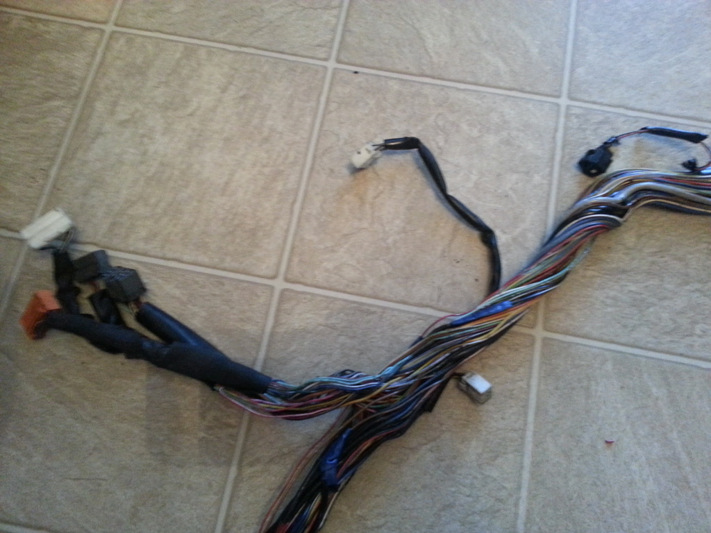
Current status of harness ... I can start merging the SC300 body plugs / wires and connectors I need. I actually found this VVTi harness easier to work with since I had less solder points having used 2 vvti harnesses. I will have to source out wiring wraps as Steve (1A1) have suggested and use them on this harness since I don't have corrugated wraps anymore.


auto trans wiring .. need to decide will I remove or keep them

I really hate soldering since I did a lot in my younger years working with PCBs when I was still practicing my Electronics Engineering profession. Exactly the reason why if it is not a close friend, I wouldn't even do a harness for anybody even if they pay me. It is boring to me but hey , doing the harness saves me $1k which I can use in go fast goodies.
Current status of harness ... I can start merging the SC300 body plugs / wires and connectors I need. I actually found this VVTi harness easier to work with since I had less solder points having used 2 vvti harnesses. I will have to source out wiring wraps as Steve (1A1) have suggested and use them on this harness since I don't have corrugated wraps anymore.


auto trans wiring .. need to decide will I remove or keep them

Last edited by gerrb; 01-05-16 at 10:19 AM.
01-05-16, 08:56 AM
#3412
gerb,
I was in the same dilemma converting my 97 auto to a 6-speed and decided to keep the auto tranny functions in the harness. However, I peeled back the wire covers to the shifter and solenoid connectors and augmented the harness with the 6-speed reverse switch by piggy-backing on the auto reverse wires. Then I re-dressed the speed sensor and reverse cables with Summit flex braiding and tucked the auto tranny wires and connectors under the intake.
Just a thought...
-scott
01-05-16, 10:09 AM
#3413
gerb,
I was in the same dilemma converting my 97 auto to a 6-speed and decided to keep the auto tranny functions in the harness. However, I peeled back the wire covers to the shifter and solenoid connectors and augmented the harness with the 6-speed reverse switch by piggy-backing on the auto reverse wires. Then I re-dressed the speed sensor and reverse cables with Summit flex braiding and tucked the auto tranny wires and connectors under the intake.
Just a thought...
-scott
I was in the same dilemma converting my 97 auto to a 6-speed and decided to keep the auto tranny functions in the harness. However, I peeled back the wire covers to the shifter and solenoid connectors and augmented the harness with the 6-speed reverse switch by piggy-backing on the auto reverse wires. Then I re-dressed the speed sensor and reverse cables with Summit flex braiding and tucked the auto tranny wires and connectors under the intake.
Just a thought...
-scott
On second thoughts , I thought of just adding wires / connectors for the 6 speed trans requirements since they go on different locations on the ECU side. There are only 2 connectors and 5 wires for the 6 speed trans any way. I will look into the Summit Flex braiding... thanks !
Last edited by gerrb; 01-05-16 at 12:27 PM.
01-05-16, 10:18 AM
#3414
As mentioned , I have decided to keep the auto transmission wiring so this harness will be useful for a 2jzgte vvti swap with auto transmission on an SC300 / SC400 later on. With an aftermarket ECU , I will have to take this harness out anyway so I might as well get it ready for another car.
VVTi TT Auto Transmission Connectors (Park / Neutral Switch , Overdrive Speed Sensor, Speed Sensor 2. Solenoid Connector)

need to replace that Park / Neutral Switch Connector Housing which is broken

Park / Neutral Switch
Pin 1 goes to Pin 2 of BF2 (should go to ( SC3 F59-26 , SC4 F59-26 , MK4 ), ( SC3 , SC4 , MK4 ) )
Pin 2 goes to Pin 6 of BF1 (should go to ( SC3 F59-16 , SC4 F59-16 , MK4 ), ( SC3 , SC4 , MK4 ) )
Pin 3 goes to Pin 9 of BF3 (should go to ( SC3 IJ1-10 , SC4 IJ1-10 , MK4 ))
Pin 4 goes to Pin 20 of B2
Pin 5 goes to Pin 13 of B2
Pin 6 goes to Pin 4 of BF3
Pin 7 goes to Pin 3 of BF3 (should go to ( SC3 F59-17 , SC4 F59-17 , MK4 ), ( SC3 , SC4 , MK4 ) )
Pin 8 goes to Pin 21 of B2
OverDrive Speed Sensor
Pin 1 goes to Pin 10 of B3
Pin 2 goes to Pin 4 of B3
Speed Sensor 2
Pin 1 goes to Pin 5 of B3
Pin 2 goes to Pin 11 of B3
Solenoid Connector
Pin 1 goes to Pin 17 of B3
Pin 2 goes to Pin 9 of B3
Pin 3 goes to Pin 8 of B3
Pin 4 goes to Pin 7 of B3
Pin 5 goes to Pin 3 of B3
Pin 6 goes to Pin 1 of B3
Pin 7 goes to Pin 18 of B2 (Ground - E2)
Pin 8 goes to Pin 15 of B3
Pin 9 goes to Pin 14 of B3
Pin 10 goes to Pin 13 of B3
Pin 11 goes to Pin 6 of B3
Pin 12 goes to Pin 2 of B3
Diagram (can be zoomed through the + at Photobucket) to verify Wiring for Park / Neutral Switch
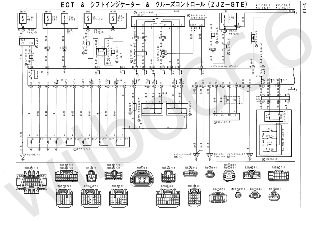
Diagram (can be zoomed through the + at Photobucket) to verify Wiring for Overdrive Speed Sensor and Speed Sensor 2

Diagram (can be zoomed through the + at Photobucket) to verify wiring for Solenoid Connector

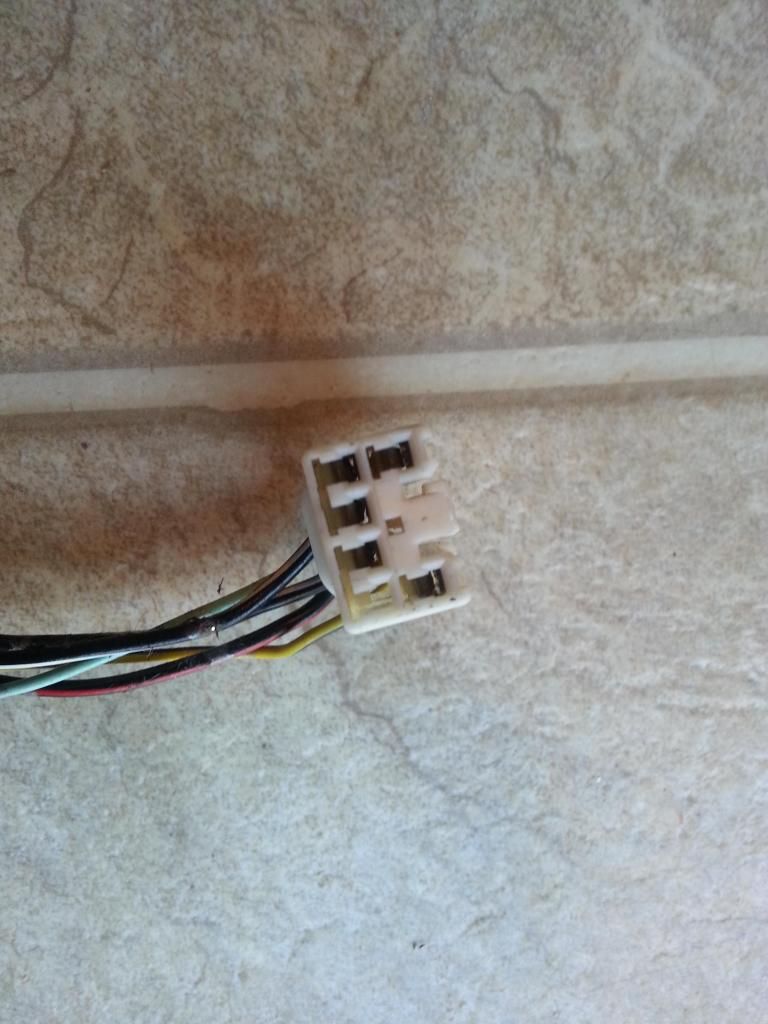
Done with the auto transmission wiring . Had replaced the broken Park/Neutral Switch Connector Housing. This harness is ready to be merged with the SC300 body plugs. Move the wires from the BF1 , BF2, BF3 plugs and populate the F59 and F60 plugs . And before I forget add 2 connectors (5 wires) for the V160 6 speed transmission.

Park / Neutral Switch Connector Housing Replaced. You have to be careful on the pin locks of this housing. They are so easy to break.

The wires from the BF1, BF2, BF3 plugs which are at the center of the picture will be moved to other plugs. The Diagnostic port and its wires will be taken out . The Igniter has already been relocated also near the ECU.

VVTi TT Auto Transmission Connectors (Park / Neutral Switch , Overdrive Speed Sensor, Speed Sensor 2. Solenoid Connector)

need to replace that Park / Neutral Switch Connector Housing which is broken

Park / Neutral Switch
Pin 1 goes to Pin 2 of BF2 (should go to ( SC3 F59-26 , SC4 F59-26 , MK4 ), ( SC3 , SC4 , MK4 ) )
Pin 2 goes to Pin 6 of BF1 (should go to ( SC3 F59-16 , SC4 F59-16 , MK4 ), ( SC3 , SC4 , MK4 ) )
Pin 3 goes to Pin 9 of BF3 (should go to ( SC3 IJ1-10 , SC4 IJ1-10 , MK4 ))
Pin 4 goes to Pin 20 of B2
Pin 5 goes to Pin 13 of B2
Pin 6 goes to Pin 4 of BF3
Pin 7 goes to Pin 3 of BF3 (should go to ( SC3 F59-17 , SC4 F59-17 , MK4 ), ( SC3 , SC4 , MK4 ) )
Pin 8 goes to Pin 21 of B2
OverDrive Speed Sensor
Pin 1 goes to Pin 10 of B3
Pin 2 goes to Pin 4 of B3
Speed Sensor 2
Pin 1 goes to Pin 5 of B3
Pin 2 goes to Pin 11 of B3
Solenoid Connector
Pin 1 goes to Pin 17 of B3
Pin 2 goes to Pin 9 of B3
Pin 3 goes to Pin 8 of B3
Pin 4 goes to Pin 7 of B3
Pin 5 goes to Pin 3 of B3
Pin 6 goes to Pin 1 of B3
Pin 7 goes to Pin 18 of B2 (Ground - E2)
Pin 8 goes to Pin 15 of B3
Pin 9 goes to Pin 14 of B3
Pin 10 goes to Pin 13 of B3
Pin 11 goes to Pin 6 of B3
Pin 12 goes to Pin 2 of B3
Diagram (can be zoomed through the + at Photobucket) to verify Wiring for Park / Neutral Switch

Diagram (can be zoomed through the + at Photobucket) to verify Wiring for Overdrive Speed Sensor and Speed Sensor 2

Diagram (can be zoomed through the + at Photobucket) to verify wiring for Solenoid Connector

Done with the auto transmission wiring . Had replaced the broken Park/Neutral Switch Connector Housing. This harness is ready to be merged with the SC300 body plugs. Move the wires from the BF1 , BF2, BF3 plugs and populate the F59 and F60 plugs . And before I forget add 2 connectors (5 wires) for the V160 6 speed transmission.

Park / Neutral Switch Connector Housing Replaced. You have to be careful on the pin locks of this housing. They are so easy to break.

The wires from the BF1, BF2, BF3 plugs which are at the center of the picture will be moved to other plugs. The Diagnostic port and its wires will be taken out . The Igniter has already been relocated also near the ECU.

Last edited by gerrb; 01-11-16 at 04:56 PM.


 01-06-16, 06:05 AM
#3416
Time to get the plugs(connectors) / wires I need from the 1997 SC300 wiring harness so I can merge them into my 2jzgte VVTi harness

The only ones I need are pictured below. Being only a handful , it does makes sense to start with the VVTi harness as my base and then merge what you need from the SC300 harness.
Body Plugs and heater valve plug
fuse box connectors, AC compressor connector , coolant gauge sensor (vvti has none), power steering assist plug , oil level sensor (aristo vvti has a different plug)

I am doing a different way of merging the SC300 plugs / wires into the 2jzgte VVTi Harness.... not like the way I did it on the 2jzgte Wiring Harness Made Easy thread. I am placing both harness side by side

then evaluate which wires / pin of each Body Plug do I need and transfer them one by one .. like on the following picture , I knew that Pin 1 & 2 of the PPS solenoid which currently goes to Pin 8 & 9 of BF1 on the VVTi harness (white connector) have to be moved into the Pin 6 & 16 of IJ2 (gray connector) , so I cut the wire on both and solder one into the other. Hope you get what I mean ... lol.

Another sample so you better understand how I moved wires / pins of the SC Body Plugs into the VVTi Harness
You remember me saying the VVTi engine do not have a coolant temperature sender for the gauge cluster ? That is with the Aristo , they have a multiplexer to get dash gauge temp from the ECU. With our SCs , it is done differently . So we need to install a coolant temperature sender for our dash gauge
Pictured below is the sender I got from one of my JZ engines and the connector which I took out from the SC300 harness

I soldered the connector to one of the alternator wires (Pin 3) I previously talked about as extra on my harness since on my SC300 , the alternator wires are on the engine bay harness .

That Pin 3 wire as I mentioned before goes to Pin 7 of BF1 .. and I know that on the SC , the water temp sender for the gauge goes to Pin 9 of IK1 so I moved it from the white connector BF1 to the orange SC plug IK1 ... So I hope by now you understand or have a better idea on how I slowly transferred wires / SC body plugs into the VVTi harness.


The only ones I need are pictured below. Being only a handful , it does makes sense to start with the VVTi harness as my base and then merge what you need from the SC300 harness.
Body Plugs and heater valve plug

fuse box connectors, AC compressor connector , coolant gauge sensor (vvti has none), power steering assist plug , oil level sensor (aristo vvti has a different plug)

I am doing a different way of merging the SC300 plugs / wires into the 2jzgte VVTi Harness.... not like the way I did it on the 2jzgte Wiring Harness Made Easy thread. I am placing both harness side by side

then evaluate which wires / pin of each Body Plug do I need and transfer them one by one .. like on the following picture , I knew that Pin 1 & 2 of the PPS solenoid which currently goes to Pin 8 & 9 of BF1 on the VVTi harness (white connector) have to be moved into the Pin 6 & 16 of IJ2 (gray connector) , so I cut the wire on both and solder one into the other. Hope you get what I mean ... lol.

Another sample so you better understand how I moved wires / pins of the SC Body Plugs into the VVTi Harness
You remember me saying the VVTi engine do not have a coolant temperature sender for the gauge cluster ? That is with the Aristo , they have a multiplexer to get dash gauge temp from the ECU. With our SCs , it is done differently . So we need to install a coolant temperature sender for our dash gauge
Pictured below is the sender I got from one of my JZ engines and the connector which I took out from the SC300 harness

I soldered the connector to one of the alternator wires (Pin 3) I previously talked about as extra on my harness since on my SC300 , the alternator wires are on the engine bay harness .

That Pin 3 wire as I mentioned before goes to Pin 7 of BF1 .. and I know that on the SC , the water temp sender for the gauge goes to Pin 9 of IK1 so I moved it from the white connector BF1 to the orange SC plug IK1 ... So I hope by now you understand or have a better idea on how I slowly transferred wires / SC body plugs into the VVTi harness.

Last edited by gerrb; 01-07-16 at 01:20 PM.
01-06-16, 11:55 AM
#3417
Going through all the diagrams one by one , I knew it will take a lot of time. I initially didn't think of going this detailed with the SC300 body plugs but decided I might as well so people will understand better (instead of me just saying this pin of plug A goes to this pin of plug B) how I figured out where each wire / pin from the body plugs connect to the 2jzgte VVTi harness. I have a 1997 SC300 so I need to use the 1997 diagrams. There are some differences between them and the diagrams I posted on the 2jzgte Wiring Harness Made Easy thread which were for 1992-1994. I will go through each wiring diagram of the 1997 SC300 / SC400 . If anyone needs the 95-96 I have them too. I actually have all info you can think of about all years of the SC300 / SC400 coming from the TIS (Toyota Technical Information System) . Anything you want to know about every model of Toyota / Lexus vehicles . Get a membership on that website and you will have a resource of whatever you want to know about our cars.
[SIZE="4"]GERRB's 1997 2jzgte VVTi V160 6speed SC BODY PLUGS PIN SUMMARY [/SIZE]
EB1 Connector

EB1
1 --> Pin 4 of the AC Connector (AC Clutch)
2 --> Pin 13 of F59 (ACMG - pin 23 of 40pin connector for non vvti 2jzgte)
3 --> Pin 2 of F59 (STA) , Pin 17 of IJ2 (M/T only) , Pin 23 of IK2 , Pin 6 of Park Neutral Switch (A/T Only)
4 --> Pin 1 of F60
5 --> EMPTY
6 --> EMPTY since I took out the Data Link Connector
7 --> Pin 1 of II1 , Pin 1 of the AC Connector
8 --> Pin 10 of F60
EB2 Connector

1 --> Starter Solenoid connector (On our VVTi Harness, starter solenoid connector goes to Pin 8 of BF2 so you need to move that wire to this pin)
2 --> EMPTY
3 --> Pin 16 of F60 , Pin 12 of IJ1 , Pin 2 of O2 Sensor (only for SC400)
IJ1 Connector

1 --> Pin 1 of Injector 1 , Pin 5 of B2 ECU Connector
2 --> Pin 2 of II1 , Pin 2 of the VSV Heater Valve
3 --> Pin 3 of Short Connector (only for SC300), Pin 1 of Coil 1 2 3 (Note that IJ1-3 and IJ1-7 merge or becomes one internally , so can be interchanged)
4 --> Pin 2 of Theft Deterrent Horn
5 --> Pin 4 of Short Connector (only for SC300), Pin 2 of O2 Sensor (only SC300) (This pin 5 of IJ2 is used differently on the SC400 since they didn't have manual transmission from factory)
6 --> Pin 9 of Park Neutral Switch (and should go to the NSW pin of the ECU) (this pin not needed for cars with Manual Transmission)
7 --> Pin 5 of Short Connector (only for SC300), Pin 2 of Injector 1 2 3 4 5 6 (Note that IJ1-3 and IJ1-7 merge or becomes one internally , so can be interchanged)
8 --> Pin 4 of F60 (DI)
9 --> Pin 1 of Theft Deterrent Horn
10 --> Pin 1 of the Speed Sensor 1, Pin 3 of the Park / Neutral Switch , Pin 2 of the Reverse Light Switch Connector (M/T Only)
11 --> EMPTY
12 --> Pin 3 of EB2, Pin 16 of F60
13 --> EMPTY (Pin 12 of Traction ECU but I have no Traction Control on my car)
14 --> Pin 5 of F60 (FPC)
IJ2 Connector

1 --> EMPTY (Radiator Cooling Fan is now mechanical clutch fan and Cruise Control Out)
2 --> EMPTY (Cruise Control Out)
3 --> EMPTY
4 --> EMPTY
5 --> EMPTY (Radiator Cooling Fan is now mechanical clutch fan )
6 --> Pin 1 of PPS Solenoid (On our VVTi Harness, Pin 1 of PPS solenoid goes to Pin 8 of BF1 so you need to move that wire to this pin)
7 --> Pin 6 of F59
8 --> EMPTY
9 --> EMPTY (Cruise Control Out)
10 --> EMPTY
11 --> Pin 9 of F60
12 --> EMPTY (I have no Traction Control)
13 --> EMPTY
14 --> EMPTY (I took out Data Link Connector)
15 --> EMPTY (Radiator Cooling Fan is now mechanical clutch fan )
16 --> Pin 2 of PPS Solenoid (On our VVTi Harness, Pin 2 of PPS solenoid goes to Pin 9 of BF1 so you need to move that wire to this pin)
17 --> Pin 3 of EB1, Pin 2 of F59 (STA) , Pin 23 of IK2 (This pin 17 of IJ2 is used differently on the SC400 since they didn't have manual transmission from factory)
IK1 Connector

1 --> Ground Intake Manifold
2 --> EMPTY
3 --> EMPTY (I have no Traction Control)
4 --> EMPTY (I have no Traction Control)
5 --> EMPTY (I have no Traction Control)
6 --> Pin 2 of the Speed Sensor 1
7 --> Pin 3 of the Speed Sensor 1
8 --> Pin 8 of Igniter , Pin 1 of Short Connector ( The pin 8 of the Igniter Connector was empty so I added a pin and wire and connected it to this Pin)
9 --> Coolant Temp Sender for the SC Dash Board Gauges (The wire used to be from Pin 3 of the Alternator Plug that was removed and went to Pin 7 of BF1)
10 --> EMPTY (I took out Diagnostic Link Connector)
11 --> Pin 2 of the Park / Neutral Switch , ( SC3 F59-16 , SC4 F59-16 , MK4 ), ( SC3 , SC4 , MK4 ) , Pin 2 of the Reverse Light Switch Connector (M/T Only)
12 --> Pin 1 of the Park / Neutral Switch , ( SC3 F59-26 , SC4 F59-26 , MK4 ), ( SC3 , SC4 , MK4 )
13 --> Pin 5 of the Park / Neutral Switch , Pin 13 of B2
14 --> Pin 7 of the Park / Neutral Switch , ( SC3 F59-17 , SC4 F59-17 , MK4 ), ( SC3 , SC4 , MK4 )
15 --> Ground Intake Manifold
16 --> Pin 4 of the Park / Neutral Switch , Pin 20 of B2
17 --> Pin 8 of the Park / Neutral Switch , Pin 21 of B2
18 --> EMPTY
19 --> Ground Intake Manifold
20 --> Pin 1 of Oil Pressure Switch (MOPS) , Pin 2 of Short Connector ( Note : On our VVTi Harness, Pin 1 of MOPS goes to Pin 8 of B2 so you need to move that wire to this pin)
21 --> EMPTY
22 --> EMPTY
23 --> Pin 1 of Oil Level Switch (MOL) ( Note : On our VVTi Harness, Pin 1 of MOL goes to Pin 6 of B1 so you need to move that wire to this pin)
IK2 Connector

1 --> EMPTY
2 --> EMPTY ( I took out the Data Link Connector)
3 --> EMPTY
4 --> EMPTY
5 --> EMPTY ( I took out the Data Link Connector)
6 --> EMPTY ( I have no Traction Control )
7 --> EMPTY ( I have no Traction Control )
8 --> EMPTY
9 --> Pin 6 of F60
10 --> EMPTY ( I took out the Data Link Connector)
11 --> EMPTY ( I have no Traction Control )
12 --> EMPTY
13 --> EMPTY ( I have no Traction Control )
14 --> EMPTY
15 --> EMPTY
16 --> EMPTY ( I have no Traction Control )
17 --> EMPTY ( I have no Traction Control )
18 --> EMPTY ( I have no Traction Control )
19 --> EMPTY
20 --> EMPTY
21 --> EMPTY ( I have no Traction Control )
22 --> EMPTY
23 --> Pin 3 of EB1 , Pin 2 of F59 (STA) , Pin 17 of IJ2 (M/T only) , Pin 6 of Park Neutral Switch (A/T Only)
24 --> Front Ground of Intake Manifold
25 --> EMPTY ( I took out the Data Link Connector)
II1 Connector

1 --> Pin 1 of the AC Connector, Pin 7 of EB1
2 --> Pin 2 of the VSV Heater Valve, Pin 2 of IJ1
3 --> EMPTY
4 --> Pin 2 of the AC Connector
5 --> Should go to the AC request Pin of the ECU but the Aristo 2jzgtte VVTi has none. Use this going to a relay to turn the AC Compressor
6 --> EMPTY
7 --> Pin 1 of the VSV Heater Valve
8 --> EMPTY
9 --> EMPTY
10 --> EMPTY
11 --> EMPTY
12 --> EMPTY
Short Connector
1 --> Pin 8 of IK1 , Pin 8 of Igniter
2 --> Pin 20 of IK1 , Pin 1 of Main OIL Pressure Switch (MOPS)
3 --> Pin 3 of IJ1 (only for SC300)
4 --> Pin 5 of IJ1 (only for SC300)
5 --> Pin 7 of IJ1 (only for SC300)
6 --> EMPTY
Before I forget this, I might as well include here the CHART. I have recommended that you start working on a CHART in the previous pages and especially on my 2JZGTE Wiring Harness Made Easy thread . I will make one on this post which is the Master Chart or the Final Chart. Remember that on the other thread I had been populating the Chart as I went through the connectors ? It helped me remember which connector I am done with and have yet to do. Here I will do the final one. It was my checklist while I was doing my final verifications on my 2jzgte VVTi Wiring Harness. I always re-check every plug / wire at least twice before I install my harness cause it will save me a lot of headaches later.
You will see where the F59 and F60 ECU plugs wires will be coming from within the chart. The chart does help you have a glance of all the connectors with their pins and will be very useful during verification / testing process of your harness once it is all said and done.
GERRB's 1997 2jzgte VVTi V160 6speed Connectors' CHART
B1 ECU CONNECTOR
1 --> Pin 1 of Injector #3
2 --> Pin 1 of Injector #4
3 --> Pin 1 of Injector #5
4 --> Pin 1 of Injector #6
5 --> Pin 2 of VSV1
6 --> EMPTY (The Main Oil Level Switch PIN 1 (should go to ( SC3 Ik1-23 , SC4 IK1-23 , MK4 )) (Note : This goes in another plug of our SC)
7 --> Pin 1 of Electronic Throttle Control ( ETCS-i Motor M-)
8 --> Pin 2 of Electronic Throttle Control ( ETCS-i Motor M+)
9 --> Ground
10 --> Pin 1 of Camshaft Sensor
11 --> Pin 7 of Igniter
12 --> Pin 6 of Igniter
13 --> Pin 5 of Igniter
14 --> EMPTY
15 --> Pin 2 of VSVPMC
16 --> EMPTY
17 --> Pin 2 of VVTi Solenoid OCV-
18 --> Pin 1 of VVTi Solenoid OCV+
19 --> Pin 4 of Electronic Throttle Control (ETCS-i Clutch CL-)
20 --> Pin 3 of Electronic Throttle Control (ETCS-i Clutch CL+)
21 --> Ground
22 --> Pin 2 of Crank Position Sensor , Pin 2 of Cam Position Sensor
23 --> Pin 1 of Crank Position Sensor
24 --> EMPTY
25 --> Pin 4 of Igniter
26 --> EMPTY (alternator charge circuit .. extra wire infront .. remember ? )
27 --> Pin 1 of Knock Sensor 2
28 --> Pin 1 of Knock Sensor 1
29 --> EMPTY (Am bringing the AC Lock Sensor signal to the SC300 AC Control Assembly)
30 --> ETCS-i Motor Shielding (grounding inside the ECU)
31--> Ground
B2 ECU CONNECTOR
1 --> EMPTY
2 --> Pin 4 of Accelerator Pedal Position Sensor , Pin 3 of Map Sensor, Pin 1 of Throttle Position Sensor
3 --> Pin 2 of VSV2
4 --> Pin 1 of O2 Sensor
5 --> Pin 1 of Injector #1
6 --> Pin 1 of Injector #2
7 --> Pin 2 of VSVPRG
8 --> EMPTY (The Main Oil Pressure Switch PIN 1 (should go to ( SC3 Ik1-20 , SC4 IK1-20 , MK4 )) (Note : This goes in another plug of our SC)
9 --> Pin 2 of Map Sensor
10 --> Pin 5 of MAF Sensor
11 --> EMPTY
12 --> Pin 3 of O2 Sensor
13 --> Pin 5 of Park / Neutral Switch
14 --> Pin 2 of Coolant Sensor
15 --> Pin 2 of Accelerator Pedal Position Sensor
16 --> Pin 1 of Accelerator Pedal Position Sensor
17 --> Pin 4 of O2 Sensor , Ground Rear Intake Manifold -> SAME
18 --> Pin 2 of MAF Sensor , Pin 1 of Coolant Sensor, Pin 3 of Accelerator Pedal Position Sensor, Pin 1 of MAP Sensor, Pin 4 of Throttle Position Sensor, Pin 7 of Solenoid Connector
19 --> Pin 3 of MAF Sensor
20 --> Pin 4 of Park / Neutral Switch
21 --> Pin 8 of Park / Neutral Switch
22 --> Pin 1 of MAF Sensor
23 --> Pin 2 of Throttle Position Sensor
24 --> Pin 3 of Throttle Position Sensor
B3 ECU CONNECTOR
1 --> Pin 6 of Solenoid Connector
2 --> Pin 12 of Solenoid Connector
3 --> Pin 5 of Solenoid Connector
4 --> Pin 2 of Overdrive Speed Sensor
5 --> Pin 1 of Speed Sensor 2
6 --> Pin 11 of Solenoid Connector
7 --> Pin 4 of Solenoid Connector
8 --> Pin 3 of Solenoid Connector
9 --> Pin 2 of Solenoid Connector
10 --> Pin 1 of Overdrive Speed Sensor
11 --> Pin 2 of Speed Sensor 2
12 --> Pin 2 of VSV3
13 --> Pin 10 of Solenoid Connector
14 --> Pin 9 of Solenoid Connector
15 --> Pin 8 of Solenoid Connector
16 --> Pin 2 of VSVFPU
17 --> Pin 1 of OIL, Automatic Transmission Oil Temperature Sensor,
F59 ECU CONNECTOR
1 --> EMPTY
2 --> Pin 3 of EB1 , Pin 23 of IK2 , Pin 17 if IJ2 (M/T Only) , Pin 6 of Park / Neutral Switch (A/T only)
3 --> Pin 5 of F60
4 --> EMPTY ( though this pin can be used with paddle shifters if you are on auto trans)
5 --> EMPTY ( removed diagnostic connector)
6 --> Pin 7 of IJ2
7 --> EMPTY (Automatic Transmission Switch Manual )
8 --> EMPTY
9 --> EMPTY
10 --> EMPTY (not using this since my AC is controlled by the SC300 AC Control Assembly ) (Ambient Air Temp Sensor - TAM)
11 --> EMPTY (ST1 - Brake Signal Switch Normally Closed)
12 --> EMPTY (PRE2 - AC Pressure Switch 2 )
13 --> ACMG (need to transfer this to a relay switch for my application so my AC will work)
14 --> EMPTY ( though this pin can be used with paddle shifters if you are on auto trans)
15 --> EMPTY
16 --> Pin 2 of the Park / Neutral Switch
17 --> Pin 7 of the Park / Neutral Switch
18 --> EMPTY (Engine Coolant Radiator TH +)
19 --> EMPTY
20 --> EMPTY (outputs a TACH signal )
21 --> EMPTY (PRE - AC Pressure Switch )
22 --> EMPTY (Engine Coolant Radiator TH -)
23 --> EMPTY
24 --> EMPTY
25 --> EMPTY
26 --> Pin 1 of the Park / Neutral Switch
27 --> EMPTY
28 --> EMPTY
F60 ECU CONNECTOR
1 --> Pin 4 of EB1 , Pin 7 of F60
2 --> EMPTY
3 --> EMPTY
4 --> Pin 8 of IJ1
5 --> Pin 14 of IJ1
6 --> Pin 9 of IK2
7 --> Pin 1 of F60 , Pin 4 of EB1
8 --> Pin 16 of F60, Pin 3 of EB2 , Pin 12 of IJ1
9 --> Pin 11 of IJ2
10 --> Pin 8 of EB1
11 --> EMPTY
12 --> EMPTY
13 --> EMPTY
14 --> EMPTY
15 --> EMPTY (NEO - Slave Engine Speed Sensor)
16 --> Pin 3 of EB2 , Pin 12 of IJ1, Pin 8 of F60
17 --> EMPTY
18 --> EMPTY
19 --> EMPTY
20 --> EMPTY
21 --> EMPTY
22 --> Ground Intake Manifold
AC COMPRESSOR (You will need to replace the Aristo 3 pin connector with that of the 4 pin SC or MKIV , the aristo vvti has a different connector)
1 --> Pin 29 of B1 (should go to ( SC3 II1-1 & EB1-7 , SC4 II1-1 & EB1-7 , MK4 ))
2 --> Ground Intake Manifold (should go to ( SC3 II1-4 , SC4 II1-4 , MK4 ))
3 --> Pin 1 of BF2 (should be ( SC3 empty , SC4 empty , MK4 ))
4 --> doesn't exist on the 3 pin Aristo vvti connector (on the SC / MKIV 4 pin connector this pin should go to ( SC3 EB1-1 , SC4 EB1-1 , MK4 ))
ACCELERATOR PEDAL POSITION SENSOR
1 --> Pin 16 of B2 ECU Connector
2 --> Pin 15 of B2 ECU Connector
3 --> Pin 2 of BF1 and Pin 18 of B2 ECU Connector (sensor ground)
4 --> Pin 2 of B2 ECU Connector (sensor B+ voltage)
CAMSHAFT SENSOR
1 --> Pin 10 of B1 ECU Connector
2 --> Pin 22 of B1 ECU Connector
COOLANT SENSOR
1 --> Pin 18 of B2 ECU Connector , Pin 2 of BF1 (E2 = Sensor ground)
2 --> Pin 14 of B2 ECU Connector
CRANK POSITION SENSOR
1 --> Pin 23 of B1 ECU Connector
2 --> Pin 22 of B1 ECU Connector
ELECTRONIC THROTTLE CONTROL CLUTCH(ETCS-i)
1 --> Pin 7 of B1 ECU Connector
2 --> Pin 8 of B1 ECU Connector
3 --> Pin 20 of B1 ECU Connector
4 --> Pin 19 of B1 ECU Connector
HEATER VALVE
1 --> Pin 7 of II1
2 --> Pin 2 of II1 , Pin 2 of IJ1
IGNITION COIL #3 (Back of Engine)
1 --> Pin 6 of BF2 (should go to ( SC3 IJ1-3 , SC4 IJ1-3 , MK4 ))
2 --> Pin 10 of Igniter (C1-)
IGNITION COIL #2 (Middle)
1 --> Pin 6 of BF2 (should go to ( SC3 IJ1-3 , SC4 IJ1-3 , MK4 ))
2 --> Pin 2 of Igniter (C3-)
IGNITION COIL #1 (Front of Engine)
1 --> Pin 6 of BF2 (should go to ( SC3 IJ1-3 , SC4 IJ1-3 , MK4 ))
2 --> Pin 1 of Igniter (C2-)
INJECTOR #1
1 --> Pin 5 of B2 ECU Connector
2 --> Pin 7 of BF2 (should go to ( SC3 IJ1-7 , SC4 IJ1-7 , MK4 ))
INJECTOR #2
1 --> Pin 6 of B2 ECU Connector
2 --> Pin 7 of BF2 (should go to ( SC3 IJ1-7 , SC4 IJ1-7 , MK4 ))
INJECTOR #3
1 --> Pin 1 of B1 ECU Connector
2 --> Pin 7 of BF2 (should go to ( SC3 IJ1-7 , SC4 IJ1-7, MK4 ))
INJECTOR #4
1 --> Pin 2 of B1 ECU Connector
2 --> Pin 7 of BF2 (should go to ( SC3 IJ1-7 , SC4 IJ1-7 , MK4 ))
INJECTOR #5
1 --> Pin 3 of B1 ECU Connector
2 --> Pin 7 of BF2 (should go to ( SC3 IJ1-7 , SC4 IJ1-7 , MK4 ))
INJECTOR #6
1 --> Pin 4 of B1 ECU Connector
2 --> Pin 7 of BF2 (should go to ( SC3 IJ1-7 , SC4 IJ1-7 , MK4 ))
IGNITER CONNECTOR
1 --> Pin 2 of Ignition Coil 1 (Front of Engine)
2 --> Pin 2 of Ignition Coil 2 (Middle of Engine)
3 --> Ground Front Intake Manifold
4 --> Pin 25 of B1
5 --> Pin 13 of B1
6 --> Pin 12 of B1
7 --> Pin 11 of B1
8 --> Pin 8 of IK1, Pin 1 of Short Connector (This was empty in my 2jzgte VVTi Harness but filled it up. Aristo 2jzgte vvti diagrams say should go to Pin 2 of BF3 . )
9 --> Pin 6 of BF2 (should go to ( SC3 IJ1-3 , SC4 IJ1-3 , MK4 ))
10 --> Pin 2 of Ignition Coil 3 (Back of Engine)
KNOCK SENSOR 1
1 --> Pin 28 of B1 ECU Connector
KNOCK SENSOR 2
1 --> Pin 27 of B1 ECU Connector
MAF SENSOR
1 --> Pin 22 of B2 ECU Connector
2 --> Pin 18 of B2 ECU Connector , Pin 2 of BF1 (E2 = Sensor ground)
3 --> Pin 19 of B2 ECU Connector
4 --> Pin 9 of BF2 and to the Diagnostic Port and to Pin 2 of O2 Sensor (B+ voltage supply) (should go to ( SC3 IJ1-5 , SC4 EB2-3 , MK4 ))
5 --> Pin 10 of B2 ECU Connector
MAP SENSOR
1 --> Pin 2 of BF1 and Pin 18 of B2 ECU Connector (sensor ground)
2 --> Pin 9 of B2 (Map Input)
3 --> Pin 2 of B2 (sensor B+ voltage)
MAIN OIL LEVEL SWITCH
1 --> Pin 6 of B1 (should go to ( SC3 Ik1-23 , SC4 IK1-23 , MK4 ))
2 --> Ground Front Intake Manifold
MAIN OIL PRESSURE SWITCH
1 --> Pin 8 of B2 (should go to ( SC3 Ik1-20 , SC4 IK1-20 , MK4 ), Pin 2 of Short Connector)
OVERDRIVE SPEED SENSOR
1 --> Pin 10 of B3 ECU Connector
2 --> Pin 4 of B3 ECU Connector
OXYGEN SENSOR
1 --> Pin 4 of B2
2 --> Pin 9 of BF2 and to the Diagnostic Port (B+ voltage supply) (should go to ( SC3 IJ1-5 , SC4 EB2-3 , MK4 ))
3 --> Pin 12 of B2
4 --> Pin 17 of B2 Plug and to the Ground connector on the intake manifold (E1 = ECU Ground)
PARK / NEUTRAL SWITCH
1 --> Pin 2 of BF2 (should go to Pin 12 of IK1 , ( SC3 F59-26 , SC4 F59-26 , MK4 ), ( SC3 , SC4 , MK4 ) )
2 --> Pin 6 of BF1 (should go to Pin 11 of IK1 , ( SC3 F59-16 , SC4 F59-16 , MK4 ), ( SC3 , SC4 , MK4 ), Pin 2 of the Reverse Light Switch Connector (M/T Only))
3 --> Pin 9 of BF3 (should go to ( SC3 IJ1-10 , SC4 IJ1-10 , MK4 ))
4 --> Pin 20 of B2 ECU Connector, Pin 16 of IK1
5 --> Pin 13 of B2 ECU Connector, Pin 13 of IK1
6 --> Pin 4 of BF3 (should go to Pin 23 of IK2 , ( SC3 EB1-3 , SC4 EB1-3 , MK4 ))
7 --> Pin 3 of BF3 (should go to Pin 14 of IK2 , ( SC3 F59-17 , SC4 F59-17 , MK4 ), ( SC3 , SC4 , MK4 ) )
8 --> Pin 21 of B2 ECU Connector, Pin 17 of IK1
9 --> Pin 5 of BF3 (should go to ( SC3 IJ1-6 , SC4 IJ1-6 , MK4 ))
PROPORTIONS POWER STEERING (PPS)
1 --> Pin 8 of BF1 (should go to ( SC3 IJ2-6 , SC4 IJ2-6 , MK4 ))
2 --> Pin 9 of BF1 (should go to ( SC3 IJ2-16 , SC4 IJ2-16 , MK4 ))
SOLENOID CONNECTOR
1 --> Pin 17 of B3 ECU Connector
2 --> Pin 9 of B3 ECU Connector
3 --> Pin 8 of B3 ECU Connector
4 --> Pin 7 of B3 ECU Connector
5 --> Pin 3 of B3 ECU Connector
6 --> Pin 1 of B3 ECU Connector
7 --> Pin 18 of B2 ECU Connector (Ground - E2)
8 --> Pin 15 of B3 ECU Connector
9 --> Pin 14 of B3 ECU Connector
10 --> Pin 13 of B3 ECU Connector
11 --> Pin 6 of B3 ECU Connector
12 --> Pin 2 of B3 ECU Connector
SPEED SENSOR 2
1 --> Pin 5 of B3 ECU Connector
2 --> Pin 11 of B3 ECU Connector
STARTER SOLENOID
1 --> Pin 8 of BF2 (should go to ( SC3 EB2-1 , SC4 EB2-1 , MK4 ))
THROTTLE POSITION SENSOR
1 --> Pin 2 of B2 (sensor B+ voltage)
2 --> Pin 23 of B2 ECU Connector
3 --> Pin 24 of B2 ECU Connector
4 --> Pin 2 of BF1 and Pin 18 of B2 (sensor ground)
VSV1
1 -->
2 --> Pin 5 of B1 ECU Connector
VSV2
1 -->
2 --> Pin 3 of B2 ECU Connector
VSV3
1 -->
2 --> Pin 12 of B3 ECU Connector
VSVFPU
1 -->
2 --> Pin 16 of B3 ECU Connector
VSVPMC
1 -->
2 --> Pin 15 of B1 ECU Connector
VSVPRG
1 -->
2 --> Pin 7 of B2 ECU Connector
VVTi SOLENOID
1 --> Pin 18 of B1 ECU Connector
2 --> Pin 17 of B1 ECU Connector
[SIZE="4"]GERRB's 1997 2jzgte VVTi V160 6speed SC BODY PLUGS PIN SUMMARY [/SIZE]
EB1 Connector

EB1
1 --> Pin 4 of the AC Connector (AC Clutch)
2 --> Pin 13 of F59 (ACMG - pin 23 of 40pin connector for non vvti 2jzgte)
3 --> Pin 2 of F59 (STA) , Pin 17 of IJ2 (M/T only) , Pin 23 of IK2 , Pin 6 of Park Neutral Switch (A/T Only)
4 --> Pin 1 of F60
5 --> EMPTY
6 --> EMPTY since I took out the Data Link Connector
7 --> Pin 1 of II1 , Pin 1 of the AC Connector
8 --> Pin 10 of F60
EB2 Connector

1 --> Starter Solenoid connector (On our VVTi Harness, starter solenoid connector goes to Pin 8 of BF2 so you need to move that wire to this pin)
2 --> EMPTY
3 --> Pin 16 of F60 , Pin 12 of IJ1 , Pin 2 of O2 Sensor (only for SC400)
IJ1 Connector

1 --> Pin 1 of Injector 1 , Pin 5 of B2 ECU Connector
2 --> Pin 2 of II1 , Pin 2 of the VSV Heater Valve
3 --> Pin 3 of Short Connector (only for SC300), Pin 1 of Coil 1 2 3 (Note that IJ1-3 and IJ1-7 merge or becomes one internally , so can be interchanged)
4 --> Pin 2 of Theft Deterrent Horn
5 --> Pin 4 of Short Connector (only for SC300), Pin 2 of O2 Sensor (only SC300) (This pin 5 of IJ2 is used differently on the SC400 since they didn't have manual transmission from factory)
6 --> Pin 9 of Park Neutral Switch (and should go to the NSW pin of the ECU) (this pin not needed for cars with Manual Transmission)
7 --> Pin 5 of Short Connector (only for SC300), Pin 2 of Injector 1 2 3 4 5 6 (Note that IJ1-3 and IJ1-7 merge or becomes one internally , so can be interchanged)
8 --> Pin 4 of F60 (DI)
9 --> Pin 1 of Theft Deterrent Horn
10 --> Pin 1 of the Speed Sensor 1, Pin 3 of the Park / Neutral Switch , Pin 2 of the Reverse Light Switch Connector (M/T Only)
11 --> EMPTY
12 --> Pin 3 of EB2, Pin 16 of F60
13 --> EMPTY (Pin 12 of Traction ECU but I have no Traction Control on my car)
14 --> Pin 5 of F60 (FPC)
IJ2 Connector

1 --> EMPTY (Radiator Cooling Fan is now mechanical clutch fan and Cruise Control Out)
2 --> EMPTY (Cruise Control Out)
3 --> EMPTY
4 --> EMPTY
5 --> EMPTY (Radiator Cooling Fan is now mechanical clutch fan )
6 --> Pin 1 of PPS Solenoid (On our VVTi Harness, Pin 1 of PPS solenoid goes to Pin 8 of BF1 so you need to move that wire to this pin)
7 --> Pin 6 of F59
8 --> EMPTY
9 --> EMPTY (Cruise Control Out)
10 --> EMPTY
11 --> Pin 9 of F60
12 --> EMPTY (I have no Traction Control)
13 --> EMPTY
14 --> EMPTY (I took out Data Link Connector)
15 --> EMPTY (Radiator Cooling Fan is now mechanical clutch fan )
16 --> Pin 2 of PPS Solenoid (On our VVTi Harness, Pin 2 of PPS solenoid goes to Pin 9 of BF1 so you need to move that wire to this pin)
17 --> Pin 3 of EB1, Pin 2 of F59 (STA) , Pin 23 of IK2 (This pin 17 of IJ2 is used differently on the SC400 since they didn't have manual transmission from factory)
IK1 Connector

1 --> Ground Intake Manifold
2 --> EMPTY
3 --> EMPTY (I have no Traction Control)
4 --> EMPTY (I have no Traction Control)
5 --> EMPTY (I have no Traction Control)
6 --> Pin 2 of the Speed Sensor 1
7 --> Pin 3 of the Speed Sensor 1
8 --> Pin 8 of Igniter , Pin 1 of Short Connector ( The pin 8 of the Igniter Connector was empty so I added a pin and wire and connected it to this Pin)
9 --> Coolant Temp Sender for the SC Dash Board Gauges (The wire used to be from Pin 3 of the Alternator Plug that was removed and went to Pin 7 of BF1)
10 --> EMPTY (I took out Diagnostic Link Connector)
11 --> Pin 2 of the Park / Neutral Switch , ( SC3 F59-16 , SC4 F59-16 , MK4 ), ( SC3 , SC4 , MK4 ) , Pin 2 of the Reverse Light Switch Connector (M/T Only)
12 --> Pin 1 of the Park / Neutral Switch , ( SC3 F59-26 , SC4 F59-26 , MK4 ), ( SC3 , SC4 , MK4 )
13 --> Pin 5 of the Park / Neutral Switch , Pin 13 of B2
14 --> Pin 7 of the Park / Neutral Switch , ( SC3 F59-17 , SC4 F59-17 , MK4 ), ( SC3 , SC4 , MK4 )
15 --> Ground Intake Manifold
16 --> Pin 4 of the Park / Neutral Switch , Pin 20 of B2
17 --> Pin 8 of the Park / Neutral Switch , Pin 21 of B2
18 --> EMPTY
19 --> Ground Intake Manifold
20 --> Pin 1 of Oil Pressure Switch (MOPS) , Pin 2 of Short Connector ( Note : On our VVTi Harness, Pin 1 of MOPS goes to Pin 8 of B2 so you need to move that wire to this pin)
21 --> EMPTY
22 --> EMPTY
23 --> Pin 1 of Oil Level Switch (MOL) ( Note : On our VVTi Harness, Pin 1 of MOL goes to Pin 6 of B1 so you need to move that wire to this pin)
IK2 Connector

1 --> EMPTY
2 --> EMPTY ( I took out the Data Link Connector)
3 --> EMPTY
4 --> EMPTY
5 --> EMPTY ( I took out the Data Link Connector)
6 --> EMPTY ( I have no Traction Control )
7 --> EMPTY ( I have no Traction Control )
8 --> EMPTY
9 --> Pin 6 of F60
10 --> EMPTY ( I took out the Data Link Connector)
11 --> EMPTY ( I have no Traction Control )
12 --> EMPTY
13 --> EMPTY ( I have no Traction Control )
14 --> EMPTY
15 --> EMPTY
16 --> EMPTY ( I have no Traction Control )
17 --> EMPTY ( I have no Traction Control )
18 --> EMPTY ( I have no Traction Control )
19 --> EMPTY
20 --> EMPTY
21 --> EMPTY ( I have no Traction Control )
22 --> EMPTY
23 --> Pin 3 of EB1 , Pin 2 of F59 (STA) , Pin 17 of IJ2 (M/T only) , Pin 6 of Park Neutral Switch (A/T Only)
24 --> Front Ground of Intake Manifold
25 --> EMPTY ( I took out the Data Link Connector)
II1 Connector

1 --> Pin 1 of the AC Connector, Pin 7 of EB1
2 --> Pin 2 of the VSV Heater Valve, Pin 2 of IJ1
3 --> EMPTY
4 --> Pin 2 of the AC Connector
5 --> Should go to the AC request Pin of the ECU but the Aristo 2jzgtte VVTi has none. Use this going to a relay to turn the AC Compressor
6 --> EMPTY
7 --> Pin 1 of the VSV Heater Valve
8 --> EMPTY
9 --> EMPTY
10 --> EMPTY
11 --> EMPTY
12 --> EMPTY
Short Connector

1 --> Pin 8 of IK1 , Pin 8 of Igniter
2 --> Pin 20 of IK1 , Pin 1 of Main OIL Pressure Switch (MOPS)
3 --> Pin 3 of IJ1 (only for SC300)
4 --> Pin 5 of IJ1 (only for SC300)
5 --> Pin 7 of IJ1 (only for SC300)
6 --> EMPTY
Before I forget this, I might as well include here the CHART. I have recommended that you start working on a CHART in the previous pages and especially on my 2JZGTE Wiring Harness Made Easy thread . I will make one on this post which is the Master Chart or the Final Chart. Remember that on the other thread I had been populating the Chart as I went through the connectors ? It helped me remember which connector I am done with and have yet to do. Here I will do the final one. It was my checklist while I was doing my final verifications on my 2jzgte VVTi Wiring Harness. I always re-check every plug / wire at least twice before I install my harness cause it will save me a lot of headaches later.
You will see where the F59 and F60 ECU plugs wires will be coming from within the chart. The chart does help you have a glance of all the connectors with their pins and will be very useful during verification / testing process of your harness once it is all said and done.
GERRB's 1997 2jzgte VVTi V160 6speed Connectors' CHART
B1 ECU CONNECTOR
1 --> Pin 1 of Injector #3
2 --> Pin 1 of Injector #4
3 --> Pin 1 of Injector #5
4 --> Pin 1 of Injector #6
5 --> Pin 2 of VSV1
6 --> EMPTY (The Main Oil Level Switch PIN 1 (should go to ( SC3 Ik1-23 , SC4 IK1-23 , MK4 )) (Note : This goes in another plug of our SC)
7 --> Pin 1 of Electronic Throttle Control ( ETCS-i Motor M-)
8 --> Pin 2 of Electronic Throttle Control ( ETCS-i Motor M+)
9 --> Ground
10 --> Pin 1 of Camshaft Sensor
11 --> Pin 7 of Igniter
12 --> Pin 6 of Igniter
13 --> Pin 5 of Igniter
14 --> EMPTY
15 --> Pin 2 of VSVPMC
16 --> EMPTY
17 --> Pin 2 of VVTi Solenoid OCV-
18 --> Pin 1 of VVTi Solenoid OCV+
19 --> Pin 4 of Electronic Throttle Control (ETCS-i Clutch CL-)
20 --> Pin 3 of Electronic Throttle Control (ETCS-i Clutch CL+)
21 --> Ground
22 --> Pin 2 of Crank Position Sensor , Pin 2 of Cam Position Sensor
23 --> Pin 1 of Crank Position Sensor
24 --> EMPTY
25 --> Pin 4 of Igniter
26 --> EMPTY (alternator charge circuit .. extra wire infront .. remember ? )
27 --> Pin 1 of Knock Sensor 2
28 --> Pin 1 of Knock Sensor 1
29 --> EMPTY (Am bringing the AC Lock Sensor signal to the SC300 AC Control Assembly)
30 --> ETCS-i Motor Shielding (grounding inside the ECU)
31--> Ground
B2 ECU CONNECTOR
1 --> EMPTY
2 --> Pin 4 of Accelerator Pedal Position Sensor , Pin 3 of Map Sensor, Pin 1 of Throttle Position Sensor
3 --> Pin 2 of VSV2
4 --> Pin 1 of O2 Sensor
5 --> Pin 1 of Injector #1
6 --> Pin 1 of Injector #2
7 --> Pin 2 of VSVPRG
8 --> EMPTY (The Main Oil Pressure Switch PIN 1 (should go to ( SC3 Ik1-20 , SC4 IK1-20 , MK4 )) (Note : This goes in another plug of our SC)
9 --> Pin 2 of Map Sensor
10 --> Pin 5 of MAF Sensor
11 --> EMPTY
12 --> Pin 3 of O2 Sensor
13 --> Pin 5 of Park / Neutral Switch
14 --> Pin 2 of Coolant Sensor
15 --> Pin 2 of Accelerator Pedal Position Sensor
16 --> Pin 1 of Accelerator Pedal Position Sensor
17 --> Pin 4 of O2 Sensor , Ground Rear Intake Manifold -> SAME
18 --> Pin 2 of MAF Sensor , Pin 1 of Coolant Sensor, Pin 3 of Accelerator Pedal Position Sensor, Pin 1 of MAP Sensor, Pin 4 of Throttle Position Sensor, Pin 7 of Solenoid Connector
19 --> Pin 3 of MAF Sensor
20 --> Pin 4 of Park / Neutral Switch
21 --> Pin 8 of Park / Neutral Switch
22 --> Pin 1 of MAF Sensor
23 --> Pin 2 of Throttle Position Sensor
24 --> Pin 3 of Throttle Position Sensor
B3 ECU CONNECTOR
1 --> Pin 6 of Solenoid Connector
2 --> Pin 12 of Solenoid Connector
3 --> Pin 5 of Solenoid Connector
4 --> Pin 2 of Overdrive Speed Sensor
5 --> Pin 1 of Speed Sensor 2
6 --> Pin 11 of Solenoid Connector
7 --> Pin 4 of Solenoid Connector
8 --> Pin 3 of Solenoid Connector
9 --> Pin 2 of Solenoid Connector
10 --> Pin 1 of Overdrive Speed Sensor
11 --> Pin 2 of Speed Sensor 2
12 --> Pin 2 of VSV3
13 --> Pin 10 of Solenoid Connector
14 --> Pin 9 of Solenoid Connector
15 --> Pin 8 of Solenoid Connector
16 --> Pin 2 of VSVFPU
17 --> Pin 1 of OIL, Automatic Transmission Oil Temperature Sensor,
F59 ECU CONNECTOR
1 --> EMPTY
2 --> Pin 3 of EB1 , Pin 23 of IK2 , Pin 17 if IJ2 (M/T Only) , Pin 6 of Park / Neutral Switch (A/T only)
3 --> Pin 5 of F60
4 --> EMPTY ( though this pin can be used with paddle shifters if you are on auto trans)
5 --> EMPTY ( removed diagnostic connector)
6 --> Pin 7 of IJ2
7 --> EMPTY (Automatic Transmission Switch Manual )
8 --> EMPTY
9 --> EMPTY
10 --> EMPTY (not using this since my AC is controlled by the SC300 AC Control Assembly ) (Ambient Air Temp Sensor - TAM)
11 --> EMPTY (ST1 - Brake Signal Switch Normally Closed)
12 --> EMPTY (PRE2 - AC Pressure Switch 2 )
13 --> ACMG (need to transfer this to a relay switch for my application so my AC will work)
14 --> EMPTY ( though this pin can be used with paddle shifters if you are on auto trans)
15 --> EMPTY
16 --> Pin 2 of the Park / Neutral Switch
17 --> Pin 7 of the Park / Neutral Switch
18 --> EMPTY (Engine Coolant Radiator TH +)
19 --> EMPTY
20 --> EMPTY (outputs a TACH signal )
21 --> EMPTY (PRE - AC Pressure Switch )
22 --> EMPTY (Engine Coolant Radiator TH -)
23 --> EMPTY
24 --> EMPTY
25 --> EMPTY
26 --> Pin 1 of the Park / Neutral Switch
27 --> EMPTY
28 --> EMPTY
F60 ECU CONNECTOR
1 --> Pin 4 of EB1 , Pin 7 of F60
2 --> EMPTY
3 --> EMPTY
4 --> Pin 8 of IJ1
5 --> Pin 14 of IJ1
6 --> Pin 9 of IK2
7 --> Pin 1 of F60 , Pin 4 of EB1
8 --> Pin 16 of F60, Pin 3 of EB2 , Pin 12 of IJ1
9 --> Pin 11 of IJ2
10 --> Pin 8 of EB1
11 --> EMPTY
12 --> EMPTY
13 --> EMPTY
14 --> EMPTY
15 --> EMPTY (NEO - Slave Engine Speed Sensor)
16 --> Pin 3 of EB2 , Pin 12 of IJ1, Pin 8 of F60
17 --> EMPTY
18 --> EMPTY
19 --> EMPTY
20 --> EMPTY
21 --> EMPTY
22 --> Ground Intake Manifold
AC COMPRESSOR (You will need to replace the Aristo 3 pin connector with that of the 4 pin SC or MKIV , the aristo vvti has a different connector)
1 --> Pin 29 of B1 (should go to ( SC3 II1-1 & EB1-7 , SC4 II1-1 & EB1-7 , MK4 ))
2 --> Ground Intake Manifold (should go to ( SC3 II1-4 , SC4 II1-4 , MK4 ))
3 --> Pin 1 of BF2 (should be ( SC3 empty , SC4 empty , MK4 ))
4 --> doesn't exist on the 3 pin Aristo vvti connector (on the SC / MKIV 4 pin connector this pin should go to ( SC3 EB1-1 , SC4 EB1-1 , MK4 ))
ACCELERATOR PEDAL POSITION SENSOR
1 --> Pin 16 of B2 ECU Connector
2 --> Pin 15 of B2 ECU Connector
3 --> Pin 2 of BF1 and Pin 18 of B2 ECU Connector (sensor ground)
4 --> Pin 2 of B2 ECU Connector (sensor B+ voltage)
CAMSHAFT SENSOR
1 --> Pin 10 of B1 ECU Connector
2 --> Pin 22 of B1 ECU Connector
COOLANT SENSOR
1 --> Pin 18 of B2 ECU Connector , Pin 2 of BF1 (E2 = Sensor ground)
2 --> Pin 14 of B2 ECU Connector
CRANK POSITION SENSOR
1 --> Pin 23 of B1 ECU Connector
2 --> Pin 22 of B1 ECU Connector
ELECTRONIC THROTTLE CONTROL CLUTCH(ETCS-i)
1 --> Pin 7 of B1 ECU Connector
2 --> Pin 8 of B1 ECU Connector
3 --> Pin 20 of B1 ECU Connector
4 --> Pin 19 of B1 ECU Connector
HEATER VALVE
1 --> Pin 7 of II1
2 --> Pin 2 of II1 , Pin 2 of IJ1
IGNITION COIL #3 (Back of Engine)
1 --> Pin 6 of BF2 (should go to ( SC3 IJ1-3 , SC4 IJ1-3 , MK4 ))
2 --> Pin 10 of Igniter (C1-)
IGNITION COIL #2 (Middle)
1 --> Pin 6 of BF2 (should go to ( SC3 IJ1-3 , SC4 IJ1-3 , MK4 ))
2 --> Pin 2 of Igniter (C3-)
IGNITION COIL #1 (Front of Engine)
1 --> Pin 6 of BF2 (should go to ( SC3 IJ1-3 , SC4 IJ1-3 , MK4 ))
2 --> Pin 1 of Igniter (C2-)
INJECTOR #1
1 --> Pin 5 of B2 ECU Connector
2 --> Pin 7 of BF2 (should go to ( SC3 IJ1-7 , SC4 IJ1-7 , MK4 ))
INJECTOR #2
1 --> Pin 6 of B2 ECU Connector
2 --> Pin 7 of BF2 (should go to ( SC3 IJ1-7 , SC4 IJ1-7 , MK4 ))
INJECTOR #3
1 --> Pin 1 of B1 ECU Connector
2 --> Pin 7 of BF2 (should go to ( SC3 IJ1-7 , SC4 IJ1-7, MK4 ))
INJECTOR #4
1 --> Pin 2 of B1 ECU Connector
2 --> Pin 7 of BF2 (should go to ( SC3 IJ1-7 , SC4 IJ1-7 , MK4 ))
INJECTOR #5
1 --> Pin 3 of B1 ECU Connector
2 --> Pin 7 of BF2 (should go to ( SC3 IJ1-7 , SC4 IJ1-7 , MK4 ))
INJECTOR #6
1 --> Pin 4 of B1 ECU Connector
2 --> Pin 7 of BF2 (should go to ( SC3 IJ1-7 , SC4 IJ1-7 , MK4 ))
IGNITER CONNECTOR
1 --> Pin 2 of Ignition Coil 1 (Front of Engine)
2 --> Pin 2 of Ignition Coil 2 (Middle of Engine)
3 --> Ground Front Intake Manifold
4 --> Pin 25 of B1
5 --> Pin 13 of B1
6 --> Pin 12 of B1
7 --> Pin 11 of B1
8 --> Pin 8 of IK1, Pin 1 of Short Connector (This was empty in my 2jzgte VVTi Harness but filled it up. Aristo 2jzgte vvti diagrams say should go to Pin 2 of BF3 . )
9 --> Pin 6 of BF2 (should go to ( SC3 IJ1-3 , SC4 IJ1-3 , MK4 ))
10 --> Pin 2 of Ignition Coil 3 (Back of Engine)
KNOCK SENSOR 1
1 --> Pin 28 of B1 ECU Connector
KNOCK SENSOR 2
1 --> Pin 27 of B1 ECU Connector
MAF SENSOR
1 --> Pin 22 of B2 ECU Connector
2 --> Pin 18 of B2 ECU Connector , Pin 2 of BF1 (E2 = Sensor ground)
3 --> Pin 19 of B2 ECU Connector
4 --> Pin 9 of BF2 and to the Diagnostic Port and to Pin 2 of O2 Sensor (B+ voltage supply) (should go to ( SC3 IJ1-5 , SC4 EB2-3 , MK4 ))
5 --> Pin 10 of B2 ECU Connector
MAP SENSOR
1 --> Pin 2 of BF1 and Pin 18 of B2 ECU Connector (sensor ground)
2 --> Pin 9 of B2 (Map Input)
3 --> Pin 2 of B2 (sensor B+ voltage)
MAIN OIL LEVEL SWITCH
1 --> Pin 6 of B1 (should go to ( SC3 Ik1-23 , SC4 IK1-23 , MK4 ))
2 --> Ground Front Intake Manifold
MAIN OIL PRESSURE SWITCH
1 --> Pin 8 of B2 (should go to ( SC3 Ik1-20 , SC4 IK1-20 , MK4 ), Pin 2 of Short Connector)
OVERDRIVE SPEED SENSOR
1 --> Pin 10 of B3 ECU Connector
2 --> Pin 4 of B3 ECU Connector
OXYGEN SENSOR
1 --> Pin 4 of B2
2 --> Pin 9 of BF2 and to the Diagnostic Port (B+ voltage supply) (should go to ( SC3 IJ1-5 , SC4 EB2-3 , MK4 ))
3 --> Pin 12 of B2
4 --> Pin 17 of B2 Plug and to the Ground connector on the intake manifold (E1 = ECU Ground)
PARK / NEUTRAL SWITCH
1 --> Pin 2 of BF2 (should go to Pin 12 of IK1 , ( SC3 F59-26 , SC4 F59-26 , MK4 ), ( SC3 , SC4 , MK4 ) )
2 --> Pin 6 of BF1 (should go to Pin 11 of IK1 , ( SC3 F59-16 , SC4 F59-16 , MK4 ), ( SC3 , SC4 , MK4 ), Pin 2 of the Reverse Light Switch Connector (M/T Only))
3 --> Pin 9 of BF3 (should go to ( SC3 IJ1-10 , SC4 IJ1-10 , MK4 ))
4 --> Pin 20 of B2 ECU Connector, Pin 16 of IK1
5 --> Pin 13 of B2 ECU Connector, Pin 13 of IK1
6 --> Pin 4 of BF3 (should go to Pin 23 of IK2 , ( SC3 EB1-3 , SC4 EB1-3 , MK4 ))
7 --> Pin 3 of BF3 (should go to Pin 14 of IK2 , ( SC3 F59-17 , SC4 F59-17 , MK4 ), ( SC3 , SC4 , MK4 ) )
8 --> Pin 21 of B2 ECU Connector, Pin 17 of IK1
9 --> Pin 5 of BF3 (should go to ( SC3 IJ1-6 , SC4 IJ1-6 , MK4 ))
PROPORTIONS POWER STEERING (PPS)
1 --> Pin 8 of BF1 (should go to ( SC3 IJ2-6 , SC4 IJ2-6 , MK4 ))
2 --> Pin 9 of BF1 (should go to ( SC3 IJ2-16 , SC4 IJ2-16 , MK4 ))
SOLENOID CONNECTOR
1 --> Pin 17 of B3 ECU Connector
2 --> Pin 9 of B3 ECU Connector
3 --> Pin 8 of B3 ECU Connector
4 --> Pin 7 of B3 ECU Connector
5 --> Pin 3 of B3 ECU Connector
6 --> Pin 1 of B3 ECU Connector
7 --> Pin 18 of B2 ECU Connector (Ground - E2)
8 --> Pin 15 of B3 ECU Connector
9 --> Pin 14 of B3 ECU Connector
10 --> Pin 13 of B3 ECU Connector
11 --> Pin 6 of B3 ECU Connector
12 --> Pin 2 of B3 ECU Connector
SPEED SENSOR 2
1 --> Pin 5 of B3 ECU Connector
2 --> Pin 11 of B3 ECU Connector
STARTER SOLENOID
1 --> Pin 8 of BF2 (should go to ( SC3 EB2-1 , SC4 EB2-1 , MK4 ))
THROTTLE POSITION SENSOR
1 --> Pin 2 of B2 (sensor B+ voltage)
2 --> Pin 23 of B2 ECU Connector
3 --> Pin 24 of B2 ECU Connector
4 --> Pin 2 of BF1 and Pin 18 of B2 (sensor ground)
VSV1
1 -->
2 --> Pin 5 of B1 ECU Connector
VSV2
1 -->
2 --> Pin 3 of B2 ECU Connector
VSV3
1 -->
2 --> Pin 12 of B3 ECU Connector
VSVFPU
1 -->
2 --> Pin 16 of B3 ECU Connector
VSVPMC
1 -->
2 --> Pin 15 of B1 ECU Connector
VSVPRG
1 -->
2 --> Pin 7 of B2 ECU Connector
VVTi SOLENOID
1 --> Pin 18 of B1 ECU Connector
2 --> Pin 17 of B1 ECU Connector
Last edited by gerrb; 10-24-16 at 02:33 PM.
01-07-16, 03:51 AM
#3419
I know it had been cold up there in Atlanta ....been here in my place in the South since before Christmas which is usually 10 degrees lower than up there. Trying to finish up the harness so when I am back up there this week hoping I can do some work on the car . I remember finishing Red Mamba Two last winter too... it was freezing when I dropped that engine in. The Black Pearl do not need much work.. just small stuff here and there then it can be fired up.
01-07-16, 12:04 PM
#3420
Driver School Candidate

Join Date: Jul 2015
Location: California
Posts: 20
Likes: 0
Received 0 Likes
on
0 Posts
Gerrb,
WOW
I spent the entire last week reading this thread, and I learned ALOT. I recently completed a 1jz swap in my sc (you probably have seen my requests for help in the perfornance section haha) and I thought that was hard, but what you have been working on is amazing. I applaud you for documenting every step for the rest of the forum readers and jz enthusiasts. I'm in charge of the electronics of my schools fsae race car and its really cool seeing how a vvti harness is modified.
Great job!
JP