When you click on links to various merchants on this site and make a purchase, this can result in this site earning a commission. Affiliate programs and affiliations include, but are not limited to, the eBay Partner Network.
^^^ Thanks guys ... yeah , am using the pre 97 lower runner .
Aside from the fact that I already have a few 2jzGTE cars , why I wanted a runaround / beater 400rwhp NA-T this time was I have six good 2jzGE long blocks in my place up North Atlanta. So if one goes kaput , I can just throw in another one. Though , I have plans to build a 2jzGE vvti engine with aftermarket parts eventually that I can push just like my cars with the 2jzGTE.
2jzGTE VVTi / 2jzGE VVTi NA-T Wiring Harness Made Easy
If you just want a very responsive daily driver SC without spending a lot of money , I would suggest go with a 2jzGE VVTi NA-T.
a) Get a healthy stock non VVTi short block (they have stronger internals than their vvti counterpart) and mate it with a healthy stock 2jzGE VVTi head using a TT head gasket. A leak down and compression tests on a long block can help you make a decision that it is a healthy long block whose parts you can use and boost.
b) Do some minor modifications on a 1998-2000 SC300 engine harness (not much to do really, most of it will be on the wiring of transmission if you are using the vvti TT transmission just like what I will use on this daily beater ) .
c) Get an exhaust manifold and a small turbo that will support 400-500rwhp so it won't be laggy, intercooler , bov, wastegate, aristo 2jzgte vvti transmission (for cheap since there are lots of them in the market), aristo 2jzgte vvti ECU without immobilizer , 440cc high impedance injectors and upgrade your fuel pump with a TT pump or something similar with the same output and some other small things like boost controller.
I promise you , if done right , you will have a very responsive daily driver without spending tons of dollars . Remember not a lot of car out there will have 400rwhp , so in a way you can fool around with almost every car on the street .
VVti gives you more torque and power down low where we spend most of our time driving specially around town. The stock NA intake manifold , having a longer runner plus plenum would help a lot on torque down low. After all , it has been proven to support 800rwhp . VVti is better on fuel consumption especially if you are going with a properly tuned aftermarket ECU and E85. . You can push a healthy stock non VVTi short block up to 600-700rwhp all day ! The secret is a good tune since torque will bend or break those stock rods and could create a window on your block .
But again, you don't have to go aftermarket ECU and E85. It you want to stay low on costs .... stay with the stock aristo vvti ecu and be at around 400-420rwhp (without going 100% on injector duty) . That power is more than enough for the majority since you will have almost equal torque number which is a fun daily driver.
I have decided to use an Aristo 2jzGTE VVTi auto transmission with a couple of coolers since I have two of them laying around . It can easily handle the 400rwhp I wanted and I don't have to spend anything acquiring a transmission. As I have mentioned on the VVTi wiring harness made easy posts from pages 227-230 (look through those pages if you haven't to better understand the wiring I am about to lay out next ) , using a 98-2000 SC300 engine harness will be the best to start with for anyone doing a 2jzGTE vvti swap or even a 2jzGE vvti NA-T.
Let me document here what I did on my harness for this beater car to help those who want to save at least $1000 on a harness . There is really nothing much to do, so save that money for go fast goodies . Like on this project , it is basically just repining / rewiring the transmission connectors and map sensor. The 1998-2000 SC300 transmission has different connectors for the solenoid and Park Neutral Switch as compared with the Aristo 2jzgte VVTi auto transmission. It wasn't really a big deal. It is even better if you are using a manual transmission . Then fewer things to do on the stock SC300 harness. You don't have to do anything on the transmission wiring except for the reverse light.
Starting with 1998-2000 SC300 stock engine harness , here is what you need to do to use it for 2jzGTE vvti swap or 2jzGE vvti NA-T assuming you are using an Aristo 2jzGTE vvti ECU. As mentioned before , get an ECU without an immobilizer . For a 2jzgte VVTi swap ,some connector locations will be different whereas for a 2jzGE vvti NA-T all connectors remain in their stock locations if you are using the stock 2jzGE intake manifold.
Any pin that you pull out, make sure you heat shrink so they don't create shortage if you are not fully taking out that wire .
Disclaimer : As I have always said many times on this thread, I won't be responsible for anything if you decide to follow whatever I write on my build thread . What I write is a guide and you have to make sure you counter check and verify since I document things after I have done things so there might be typo errors or things that I missed. But I try my best to counter check / verify what I write .
2jzGTE VVTi / 2jzGE VVTi NA-T Wiring Harness Made Easy
B1 ECU CONNECTOR (ECU-A Connector on your 1998-2000 SC300 Wiring Diagrams)
1 --> Pin 1 of Injector #3 (**As Is**)
2 --> Pin 1 of Injector #4 (**As Is**)
3 --> Pin 1 of Injector #5 (**As Is**)
4 --> Pin 1 of Injector #6 (**As Is**)
5 --> Pin 2 of VSV1 (**As Is**)
6 --> EMPTY (**As Is**)
7 --> Pin 1 of Electronic Throttle Control ( ETCS-i Motor M-) (**As Is**)
8 --> Pin 2 of Electronic Throttle Control ( ETCS-i Motor M+) (**As Is**)
9 --> Ground Front Intake Manifold (**As Is**)
10--> Pin 1 of Camshaft Sensor (**As Is**)
11 --> Pin 7 of Igniter (**As Is**)
12 --> Pin 6 of Igniter (**As Is**)
13 --> Pin 5 of Igniter (**As Is**)
14 --> EMPTY (**As Is**)
15 --> EMPTY (**As Is**)
16 --> Pin 2 of PS Oil Pressure Switch (**Pull this pin out and leave it EMPTY**)
17 --> Pin 2 of VVTi Solenoid OCV- (**As Is**)
18 --> Pin 1 of VVTi Solenoid OCV+ (**As Is**)
19 --> Pin 4 of Electronic Throttle Control (ETCS-i Clutch CL-) (**As Is**)
20 --> Pin 3 of Electronic Throttle Control (ETCS-i Clutch CL+) (**As Is**)
21 --> Ground Rear Intake Manifold (**As Is**)
22 --> Pin 2 of Camshaft Position Sensor , Pin 2 of Crankshaft Sensor (**As Is**)
23 --> Pin 1 of Crankshaft Position Sensor (**As Is**)
24 --> Pin 6 of IJ1 (**Pull this pin out and leave it EMPTY**)
25 --> Pin 4 of Igniter (**As Is**)
26 --> EMPTY (**As Is**)
27 --> Pin 1 of Knock Sensor 2 (**As Is**)
28 --> Pin 1 of Knock Sensor 1 (**As Is**)
29 --> EMPTY (**As Is**)
30 --> ETCS-i Motor Shielding (grounding inside the ECU) (**As Is**)
31--> Ground Rear Intake Manifold (**As Is**)
B2 ECU CONNECTOR
1 --> Ground Rear Side of Cylinder Head ( **leave this empty**)
2 --> Pin 4 of Accelerator Pedal Position Sensor , Pin 1 of Throttle Position Sensor, Pin 8 of IJ2 (**As Is for the first 2 then remove the connection Pin 8 of IJ2 and make a connection to Pin 3 of MAP**)
3 --> Pin 1 of O2 Sensor 2 (**leave this empty**)
4 --> Pin 1 of O2 Sensor (**As Is**)
5 --> Pin 1 of Injector #1 , Pin 1 of IJ1 (**As Is**)
6 --> Pin 1 of Injector #2 (**As Is**)
7 --> Pin 2 of VSVPRG (**As Is**)
8 --> EMPTY (**As Is**)
9 --> EMPTY (**should go to Pin 2 of Map Sensor**)
10 --> Pin 5 of MAF Sensor (**As Is**)
11 --> Pin 3 of O2 Sensor 2 (**leave this empty**)
12 --> Pin 3 of O2 Sensor (**As Is**)
13 --> Pin 14 of IJ2 (**should go to Pin 5 of PNSW**)
14 --> Pin 2 of Coolant Sensor (**As Is**)
15 --> Pin 2 of Accelerator Pedal Position Sensor (**As Is**)
16 --> Pin 1 of Accelerator Pedal Position Sensor (**As Is**)
17 --> Pin 4 of O2 Sensor , Ground Rear Intake Manifold , (**As Is)
18 --> Pin 2 of MAF Sensor , Pin 1 of Coolant Sensor, Pin 3 of Accelerator Pedal Position Sensor, Pin 4 of Throttle Position Sensor, Pin 7 of Solenoid-ATF Temp Sensor , Pin 10 of IJ2(**As Is for the first 5 then remove the connection Pin 10 of IJ2 and make a connection to Pin 1 of MAP**)
19 --> Pin 3 of MAF Sensor (**As Is**)
20 --> Pin 2 of PNSW (**should go to Pin 4 of PNSW**)
21 --> Pin 3 of PNSW (**should go to Pin 8 of PNSW**)
22 --> Pin 1 of MAF Sensor (**As Is**)
23 --> Pin 2 of Throttle Position Sensor (**As Is**)
24 --> Pin 3 of Throttle Position Sensor (**As Is**)
B3 ECU CONNECTOR
1 --> Pin 5 of Solenoid Connector (**should go to Pin 6 of Solenoid Connector **)
2 --> Pin 10 of Solenoid Connector (**should go to Pin 12 of Solenoid Connector **)
3 --> Pin 5 of Solenoid Connector (** Non Existent on SC300 **) (keep my wiring)
4 --> Pin 2 of Overdrive Speed Sensor (**As Is**)
5 --> Pin 1 of Speed Sensor 2 (**As Is**)
6 --> Pin 11 of Solenoid Connector (** Non Existent on SC300 **) (keep my wiring)
7 --> Pin 4 of Solenoid Connector (**As Is**)
8 --> Pin 3 of Solenoid Connector (**As Is**)
9 --> Pin 2 of Solenoid Connector (**As Is**)
10 --> Pin 1 of Overdrive Speed Sensor (**As Is**)
11 --> Pin 2 of Speed Sensor 2 (**As Is**)
12 --> Pin 9 of IJ2 (**leave this empty**)
13 --> Pin 9 of Solenoid Connector (**should go to Pin 10 of Solenoid Connector **)
14 --> Pin 8 of Solenoid Connector (**should go to Pin 9 of Solenoid Connector **)
15 --> Pin 7 of Solenoid Connector (**should go to Pin 8 of Solenoid Connector **)
16 --> Pin 3 of IK2 (**leave this empty**)
17 --> Pin 1 of ATF Temperature Sensor (**As Is**)
F59 ECU CONNECTOR
1 --> AC Air Condition Control Assembly (*leave this empty)
2 --> Pin 5 of PNSW, Pin 3 of EB1 , Pin 23 of IK2 , Pin 17 if IJ2 (M/T Only) (**should go to Pin 6 of PNSW, Pin 3 of EB1 , Pin 23 of IK2 , Pin 17 if IJ2 (M/T Only)**)
3 --> EMPTY (**should go to Pin 5 of F60, Pin 14 of IJ1**)
4 --> EMPTY (** I used this as my Right Shift Paddle -keep my wiring or leave this empty if you won’t use shift paddles**)
5 --> Pin 11 TC of Data Link Connector D1(**You can keep this empty or keep the wiring for the Diagnostic Port**)
6 --> Pin 7 of IJ2 (**As Is**)
7 --> Pin 6 of IK2 (**As Is**)
8 --> SC300 has this to an O2 sensor (**leave this empty**)
9 --> EMPTY (**As Is**)
10 --> EMPTY (**As Is**)
11 --> Pin 1 of IJ2 (**As Is**)
12 --> Pin 21 of IK1 trans PWR switch (*leave this empty*)
13 --> Pin 2 of EB-1 (**As Is**)
14 --> EMPTY (** I used this as my Left Shift Paddle - keep my wiring or leave this empty if you won’t use shift paddles**)
15 --> EMPTY (**As Is**)
16 --> Pin 8 of PNSW (**should go to Pin 2 of PNSW**)
17 --> Pin 9 of PNSW (**should go to Pin 7 of PNSW**)
18 --> EMPTY (**As Is**)
19 --> EMPTY (**As Is**)
20 --> outputs a TACH signal (**leave this empty**)
21 --> Pin 18 of IK2 shift lock ecu (**leave this empty**)
22 --> EMPTY (**As Is**)
23 --> Pin 2 of IJ2 (**As Is**)
24 --> EMPTY (** As Is**)
25 --> EMPTY (** As Is**)
26 --> Pin 11 of IJ1 (**should go to Pin 1 of the PNSW**)
27 --> Pin 18 of IK2 RSPD (**leave this empty**)
28 --> Pin 6 of IK1 (**leave this empty**)
F60 ECU CONNECTOR
1 --> Pin 4 of EB1 (**As Is**)
2 --> Pin 7 of IK1 (** leave this empty**)
3 --> Pin 17 of IK2 (** leave this empty**)
4 --> Pin 8 of IJ1 (**As Is**)
5 --> Pin 14 of IJ1 , Pin 3 of F59 (keep my wiring)
6 --> Pin 9 of IK2 (**As Is**)
7 --> Pin 13 of IJ1 (**As Is**)
8 --> Pin 16 of F60, Pin 3 of EB2 , Pin 12 of IJ1 (**As Is**)
9 --> Pin 11 of IJ2 (**As Is**)
10 --> Pin 8 of EB1 (**As Is**)
11 --> Pin 18 of IK1 (**As Is**)
12 --> EMPTY (**As Is**)
13 --> TRC+ (**leave this empty for those without traction control**)
14 --> ENG+ (**leave this empty for those without traction control**)
15 --> NEO+ (**leave this empty for those without traction control**)
16 --> Pin 3 of EB2 , Pin 12 of IJ1, Pin 8 of F60 (**As Is**)
17 --> EMPTY (**As Is**)
18 --> EMPTY (**As Is**)
19 --> EMPTY (**As Is**)
20 --> TRC- (**leave this empty for those without traction control**)
21 --> ENG- (**leave this empty for those without traction control**)
22 --> Pin 3 of IJ2 (**As Is**)
EB1 Connector
1 --> Pin 4 of AC Compressor(**As Is**)
2 --> Pin 13 of F59 (**As Is**)
3 --> Pin 5 of PNSW , Pin 2 of F59 (STA) , Pin 23 of IK2 , Pin 17 of IJ2 (M/T only) (** should go to Pin 6 of PNSW , Pin 2 of F59 (STA) , Pin 23 of IK2 , Pin 17 of IJ2 (M/T only)**)
4 --> Pin 1 of F60 (**As Is**)
5 --> Empty (**As Is**)
6 --> Pin 23 of Data Link Connector 1 D1 (**You can keep this empty or keep the wiring for the Diagnostic Port**)
7 --> Pin 1 of II1 , Pin 1 of AC Compressor (**As Is**)
8 --> Pin 10 of F60 (**As Is**)
EB2 Connector
1 --> Starter Solenoid (**As Is**)
2 --> Empty
3 --> Pin 12 of IJ1 , Pin 8 of F60 , Pin 16 of F60 (**As Is**)
IK1 Connector
1 --> Ground Intake Manifold Front Side ((**As Is**)plus Pin 1 of Power Steering Oil Pressure Switch))
2 --> EMPTY (**As Is**)
3 --> EMPTY (**As Is**)
4 --> EMPTY (**As Is**)
5 --> EMPTY (**As Is**)
6 --> Pin 28 PWRL (**should go to Pin 2 of the Speed Sensor 1**)
7 --> Pin 2 SND (** should go to Pin 3 of the Speed Sensor 1 **)
8 --> Pin 8 of Igniter , Pin 1 of Short Connector
9 --> Pin 1 of Water Temp Sender Gauge , Pin 7 of Short Connector (**As Is**)
10 --> Pin 11 of Data Link Connector 1 D1 (**You can keep this empty or keep the wiring for the Diagnostic Port**)
11 --> Pin 8 of PNSW (**should go to Pin 2 of PNSW , Pin 16 of F59**)
12 --> Pin 7 of PNSW (**should go to Pin 1 of PNSW , Pin 26 of F59
13 --> Pin 10 of PNSW (**should go to Pin 5 of PNSW , Pin 13 of B2 ECU Connector**)
14 --> Pin 9 of PNSW (**should go to Pin 7 of PNSW , Pin 17 of F59**)
15 --> Ground Intake Manifold Rear Side (**As Is**)
16 -->Pin 2 of PNSW (**should go to Pin 4 of PNSW , Pin 20 of B2 ECU Connector**)
17 -->Pin 3 of PNSW(**should go to Pin 8 of PNSW , Pin 21 of B2 ECU Connector**)
18 --> Pin 11 of F60 (**As Is**)
19 --> Ground Intake Manifold (**As Is**)
20 --> Pin 1 of Oil Pressure Switch (**As Is**)
21 --> Pin 12 PWR (**leave this empty**)
22 --> Pin 20 (**leave this empty**)
23 --> Pin 1 of Oil Level Switch Sensor (**As Is**)
IK2 Connector
1 --> Pin 24 OX2B (**leave this empty**)
2 --> Pin 22 of Data Link Connector 1 D1 (**You can keep this empty or keep the wiring for the Diagnostic Port**)
3 --> Pin 16 PI (**leave this empty**)
4 --> Pin 22 of F84 ECU Connector (**leave this empty-ECU should be no immobilizer**)
5 --> Pin 21 of F84 ECU Connector (**leave this empty-ECU should be no immobilizer**)
6 --> Pin 7 of F59(**As Is**)
8 --> Pin 25 HT2B(**leave this empty**)
9 --> Pin 6 of F60 (**As Is**)
10 -->Pin 5 of Data Link Connector 1 (**You can keep this empty or keep the wiring for the Diagnostic Port**)
11 --> EMPTY (**As Is**)
12 --> EMPTY (**As Is**)
13 --> EMPTY (**As Is**)
14 --> EMPTY (**As Is**)
15 --> Pin 23 of F84 ECU Conector (**leave this empty-ECU should be no immobilizer**)
16 -->Pin 9 ECM(**leave this empty**)
17 --> Pin 3 SMSW(**leave this empty**)
18 --> Pin 27 RSPD for shift lock (**leave this empty**)
19 --> EMPTY (**As Is**)
20 --> EMPTY (**As Is**)
23 --> Pin 5 of PNSW , Pin 3 of EB1 , Pin 2 of F59 (STA) , Pin 17 of IJ2 (M/T only) (**should go to Pin 6 of PNSW , Pin 3 of EB1 , Pin 2 of F59 (STA) , Pin 17 of IJ2 (M/T only)**)
24 --> Ground Front Side of Intake Manifold (**As Is**)
25 --> Pin 16 of Data Link Connector 1 D1 (**You can keep this empty or keep the wiring for the Diagnostic Port**)
IJ1 Connector
1 --> Pin 1 of Injector 1 ,Pin 5 of B2 ECU Connector (**As Is**)
2 --> Pin 2 of II1 , Pin 2 of the VSV Heater Valve (**As Is**)
3 --> Pin 3 of Short Connector , Pin 2 of Injectors 2 / 4 / 5 / 6 (**As Is**)
4 --> Pin 2 of Theft Deterrent Horn (**As Is**)
5 --> Pin 4 of MAF Sensor, Pin 2 of O2 Sensor , Pin 1 of VSV-PRG , Pin 1 of VSV1-ACIS, Pin 12 B+Data Link Connector D1 (**As Is**)
6 --> Pin 6 of PNSW, Pin 24 of B1 ECU-A Connector (**should go to Pin 9 of PNSW**)
7 --> Pin 5 of Short Connector , Pin 1 of Coils 1 / 2 / 3 , Pin 1 of Noise Filter , Pin 9 of Igniter , Pin 2 of Injectors 1 / 3 (**As Is**)
8 --> Pin 4 of F60 (DI) (**As Is**)
9 --> Pin 1 of Theft Deterrent Horn (**As Is**)
10 -->Pin 4 of PNSW (** should go to Pin 3 of PNSW ,Pin 1 of the Speed Sensor 1 , Pin 2 of the Reverse Light Switch(M/T Only) **)
11 --> Pin 26 of F59 (**leave this empty–ECU pin used by VVTi TT Auto Trans**)
12 --> Pin 3 of EB2 , Pin 8 of F60 , Pin 16 of F60 (**As Is**)
13 --> Pin 7 of F60 (**As Is**)
14 --> Pin 5 of F60 (FPC) (**As Is**)
Note about : IJ1-3 & IJ1-7
They are connected internally so whatever is connected to IJ1-3 technically is connected to IJ1-7
IJ2 Connector
1 --> Pin 11 of F59 (** As Is**)
2 --> Pin 23 of F59 (** As Is**)
3 --> Pin 22 of F60 (** As Is**)
4 --> Pin 13 TBP (**leave this empty **)
5 --> Empty (** As Is**)
6 --> Pin 1 of PPS Solenoid (** As Is**)
7 --> Pin 6 of F59 (** As Is**)
8 -->Pin 1 of TPS , Pin 4 of APPS (**leave this empty**)
9 --> Pin 12 of B3 ECU Connector (**leave this empty**)
10 --> Pin 2 of MAF , Pin 1 of Coolant Temp Sensor , Pin 4 of TPS , Pin 3 of APPS (**leave this empty**)
11 --> Pin 9 of F60 (** As Is**)
12 --> Pin 10 of F84 ECU-F Connector (**leave this empty-ECU should have no immobilizer**)
13 --> Pin 18 of F59 ECU-D Connector (**leave this empty**)
14 --> Pin 13 of B2 ECU-B Connector (**leave this empty–ECU pin used by VVTi TT Auto Trans**)
15 --> Empty (** As Is**)
16 --> Pin 2 of PPS Solenoid (** As Is**)
II1 Connector
1 --> Pin 1 of the AC Connector , Pin 7 of EB1 (**As Is**)
2 --> Pin 2 of the VSV Heater Valve, Pin 2 of IJ1 (**As Is**)
3 --> EMPTY (**As Is**)
4 --> Pin 2 of the AC Connector (**As Is**)
5 --> Should go to the AC request Pin of the ECU but the Aristo 2jzgtte VVTi has none. Use a relay to activate compressor.
6 --> EMPTY (**As Is**)
7 --> Pin 1 of the VSV Heater Valve (**As Is**)
8 --> EMPTY (**As Is**)
9 --> EMPTY (**As Is**)
10 --> EMPTY (**As Is**)
11 --> EMPTY (**As Is**)
12 --> EMPTY (**As Is**)
2jzGTE VVTi / 2jzGE VVTi NA-T Wiring Harness Made Easy
AC COMPRESSOR (You will need to replace the Aristo 3 pin connector with that of the 4 pin SC or MKIV , the aristo vvti has a different connector)
1 --> Pin 1 of II1 , Pin 7 of EB-1 (**As Is**)
2 --> Pin 4 of II1 (**As Is**)
3 --> Empty (**As Is**)
4 --> Pin 1 of EB-1 (**As Is**)
ACCELERATOR PEDAL POSITION SENSOR
1 --> Pin 16 of B2 ECU Connector (**As Is**)
2 --> Pin 15 of B2 ECU Connector (**As Is**)
3 --> Pin 18 of B2 ECU Connector , Pin 1 of Coolant Sensor, Pin 2 of MAF , Pin 4 of TPS , Pin 7 of Solenoid - ATF Temp Sensor , Pin 10 of IJ2 (** As Is for the first 5 and remove connection to Pin 10 of IJ2 and make a connection straight to Pin 1 of the Map sensor**)
4 -->Pin 2 of B2 ECU Connector , Pin 1 of TPS , Pin 8 of IJ2 (**As Is for the first two and remove the connection to Pin 8 of IJ2 and make a connection straight to Pin 3 of Map Sensor**)
COOLANT SENSOR
1 --> Pin 18 of B2 ECU Connector , Pin 2 of MAF , Pin 4 of TPS , Pin 3 of APPS, Pin 7 of Solenoid- ATF Temp Sensor , Pin 10 of IJ2 (** As Is for the first 5 and remove connection to Pin 10 of IJ2 and make a connection straight to Pin 1 of the Map sensor**)
2 --> Pin 14 of B2 ECU Connector (**As Is**)
CRANK POSITION SENSOR
1 --> Pin 23 of B1 ECU Connector (**As Is**)
2 --> Pin 22 of B1 ECU Connector (**As Is**)
ELECTRONIC THROTTLE CONTROL CLUTCH(ETCS-i)
1 --> Pin 7 of B1 ECU Connector (**As Is**)
2 --> Pin 8 of B1 ECU Connector (**As Is**)
3 --> Pin 20 of B1 ECU Connector (**As Is**)
4 --> Pin 19 of B1 ECU Connector (**As Is**)
HEATER VALVE
1 --> Pin 7 of II1 (**As Is**)
2 --> Pin 2 of II1 , Pin 2 of IJ1 (**As Is**)
IGNITION COIL #1 (Front of Engine)
1 --> Pin 7 of IJ1 (**As Is**)
2 --> Pin 1 of Igniter (C2-) (**As Is**)
MAF SENSOR
1 --> Pin 22 of B2 ECU Connector (**As Is**)
2 --> Pin 18 of B2 ECU Connector , Pin 1 of Coolant Sensor, Pin 3 of Accelerator Pedal Position Sensor, Pin 4 of TPS , Pin 7 of Solenoid - ATF Temp Sensor , Pin 10 of IJ2 (** As Is for the first 5 and remove connection to Pin 10 of IJ2 and make a connection straight to Pin 1 of the Map sensor**)
3 --> Pin 19 of B2 ECU Connector (**As Is**)
4 --> Pin 5 of IJ1 , Pin 2 of O2 Sensor , Pin 1 of VSV-PRG , Pin 1 of VSV1-ACIS
5 --> Pin 10 of B2 ECU Connector (**As Is**)
MAP SENSOR
1 --> Pin 18 of B2 ECU Connector , Pin 2 of MAF Sensor, Pin 1 of Coolant Sensor, Pin 3 of Accelerator Pedal Position Sensor ,Pin 4 of TPS , Pin 7 of Solenoid - ATF Temp Sensor
2 --> Pin 9 of B2 ECU Connector
3 --> Pin 2 of B2 ECU Connector , Pin 4 of Accelerator Pedal Position Sensor , Pin 1 of TPS
OIL LEVEL SWITCH
1 --> Pin 23 of IK1 (**As Is**)
2 --> Ground Rear Side of Intake Manifold (**As Is**)
OXYGEN SENSOR
1 --> Pin 4 of B2 ECU Connector (**As Is**)
2 --> Pin 4 of MAF 4 , Pin 5 of IJ1 , Pin 2 of O2 Sensor , Pin 1 of VSV-PRG , Pin 1 of VSV1-ACIS (**As Is**)
3 --> Pin 12 of B2 ECU Connector (**As Is**)
4 --> Pin 17 of B2 ECU Connector and to the Rear Ground connector on the intake manifold (E1 = ECU Ground) (**As Is**)
PARK / NEUTRAL SWITCH ( You will have to replace the 10 pin PNSW connector of the SC300 with the 9 pin PNSW connector of the Aristo 2jzgte VVTi )
1 --> EMPTY
2 --> Pin 16 of IK1 , Pin 20 of B2 ECU Connector (**should go to Pin 4 of PNSW, Pin 16 of IK1, Pin 20 of B2 ECU Connector**)
3 --> Pin 17 of IK1 , Pin 21 of B2 ECU Connector (**should go to Pin 8 of PNSW, Pin 17 of IK1, Pin 21 of B2 ECU Connector**)
4 --> Pin 10 of IJ1 (**should go to Pin 3 of the PNSW **)
5 --> Pin 23 of IK2 , Pin 3 of EB1 , Pin 2-STA of F59 (**should go to Pin 6 of PNSW, Pin 23 of IK2 , Pin 3 of EB1 , Pin 2-STA of F59**)
6 --> Pin 6 of IJ1 , Pin 24-NSW of F59 (**should go to Pin 9 of PNSW, Pin 6 of IJ1**)
7 --> Pin 12 of IK1 (**should go to Pin 1 of PNSW , Pin 26 of F59 (Pin 26 of F59 currently goes to Pin 11 of IJ1… move it here ) , Pin 12 of IK1 **)
8 --> Pin 11 of IK1 , Pin 16 of F59(**should go to Pin 2 of PNSW, Pin 16 of F59 , Pin 11 of IK1**)
9 --> Pin 14 of IK1 , Pin 17 of F59 (**should go to Pin 7 of PNSW, Pin 17 of F59, Pin 14 of IK1**)
10 --> Pin 13 of IK1 (**should go to Pin 5 of PNSW , Pin 13 of IK1, Pin 13 of B2 ECU Connector(Pin 13 of B2 currently goes to Pin 14 of IJ2.. move it here) **)
PROPORTIONS POWER STEERING (PPS)
1 --> Pin 6 of IJ2 (**As Is**)
2 --> Pin 16 of IJ2 (**As Is**)
SOLENOID (Replace the SC300 10 pin solenoid connector with the Aristo VVTi 12 pin solenoid connector)
1 --> Pin 17 of B3 ECU Connector (**As Is**)
2 --> Pin 9 of B3 ECU Connector (**As Is**)
3 --> Pin 8 of B3 ECU Connector (**As Is**)
4 --> Pin 7 of B3 ECU Connector (**As Is**)
5 --> Pin 1 of B3 ECU Connector (**should go to Pin 3 of B3 ECU Connector-wire to ECU should be added since it doesn't exist now**)
6 --> Pin 18 of B2 ECU Connector (**should go to Pin 1 of B3 ECU Connector**)
7 --> Pin 15 of B3 ECU Connector (**should go to Pin 18 of B2 ECU Connector**)
8 --> Pin 14 of B3 ECU Connector (**should go to Pin 15 of B3 ECU Connector**)
9 --> Pin 13 of B3 ECU Connector (**shoud go to Pin 14 of B3 ECU Connector**)
10 --> Pin 2 of B3 ECU Connector (**should go to Pin 13 of B3 ECU Connector**)
11 --> Non Existent on SC300 (**should go to Pin 6 of B3 ECU Connector -wire to ECU should be added since it doesn't exist now**)
12 --> Non Existent on SC300 (**should go to Pin 2 of B3 ECU Connector**)
THEFT DETERRENT HORN
1 --> Pin 9 of IJ1 (**As Is**)
2 --> Pin 4 of IJ1 (**As Is**)
THROTTLE POSITION SENSOR
1 --> Pin 2 of B2 ECU Connector , Pin 4 of Accelerator Pedal Position Sensor , Pin 8 of IJ2 (**As Is for the first two and remove the connection to Pin 8 of IJ2 and make a connection straight to Pin 3 of Map Sensor**)
2 --> Pin 23 of B2 ECU Connector (**As Is**)
3 --> Pin 24 of B2 ECU Connector (**As Is**)
4 --> Pin 18 of B2 ECU Connector , Pin 1 of Coolant Sensor, Pin 3 of Accelerator Pedal Position Sensor, Pin 2 of MAF , Pin 7 of Solenoid - ATF Temp Sensor , Pin 10 of IJ2 (** As Is for the first 5 and remove connection to Pin 10 of IJ2 and make a connection straight to Pin 1 of the Map sensor**)
VSV1-ACIS
1 --> Pin 5 of IJ1 , Pin 4 of MAF Sensor, Pin 2 of O2 Sensor , Pin 1 of VSV-(**As Is**)
2 --> Pin 5 of B1 ECU Connector (**As Is**)
VSV-PRG
1 --> Pin 5 of IJ1 , Pin 4 of MAF Sensor, Pin 2 of O2 Sensor , Pin 1 of VSV1-ACIS (**As Is**)
2 --> Pin 7 of B2 ECU Connector (**As Is**)
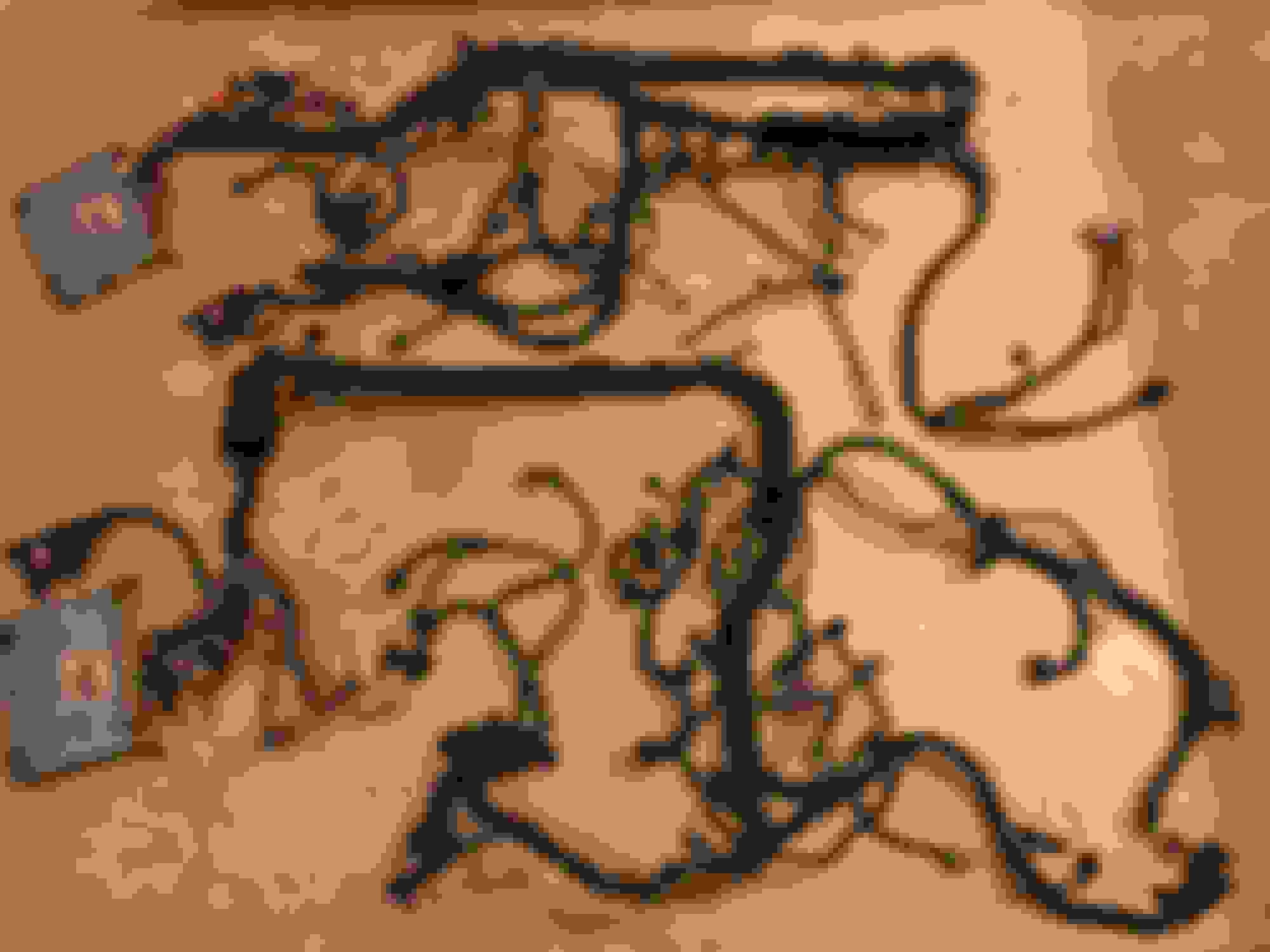
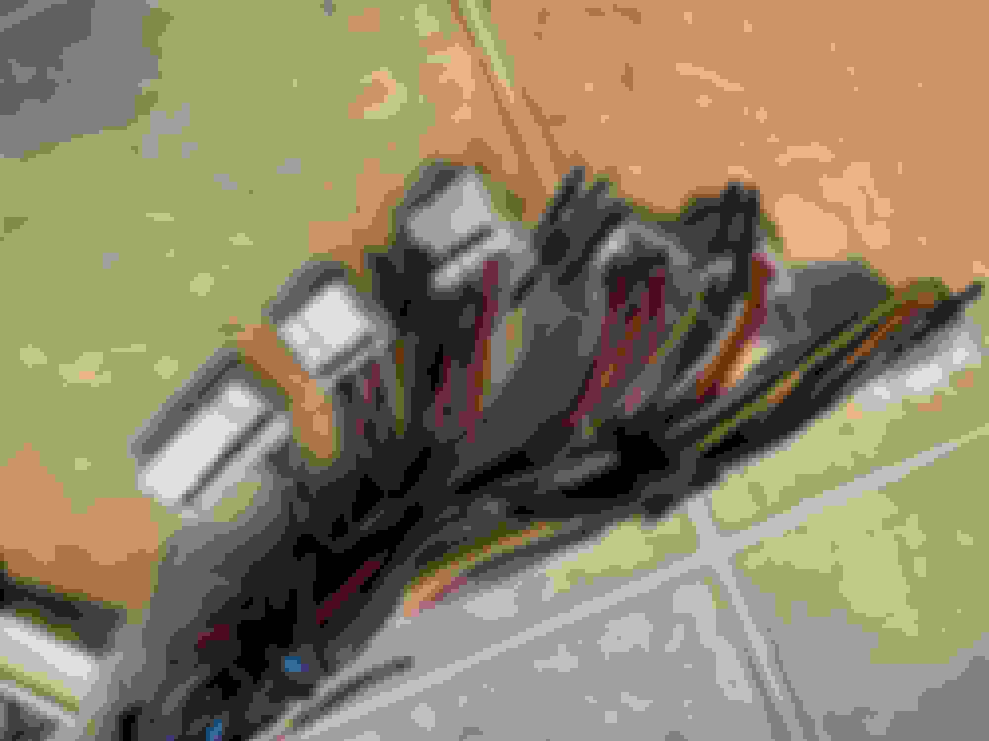
To give you an idea of the finished products : 2jzGE vvti NA-T engine harness (top) and a 2jzGTE vvti engine harness (bottom)
For the 2jzGE vvti NA-T harness , the original / stock 1998-2000 SC300 harness was barely disturbed. Any needed wiring and pins that didn't exist where taken out from existing wires and pins that where not needed and just moved around .
Since I was using an Aristo VVTi TT auto transmission on this beater car which can easily handle 400-500rwhp with a couple of good transmission oil coolers , majority of the work on the harness were on the transmission connectors
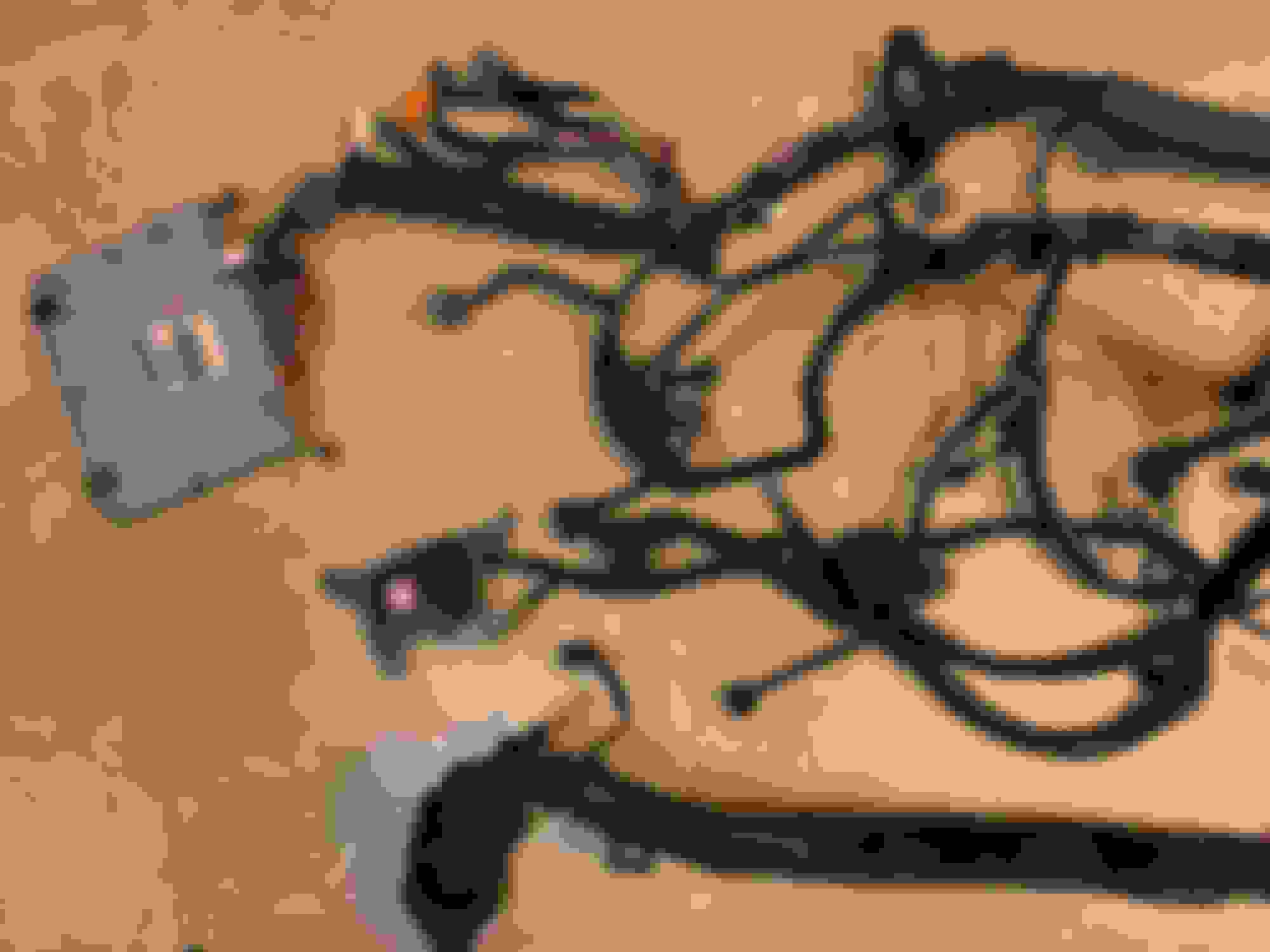
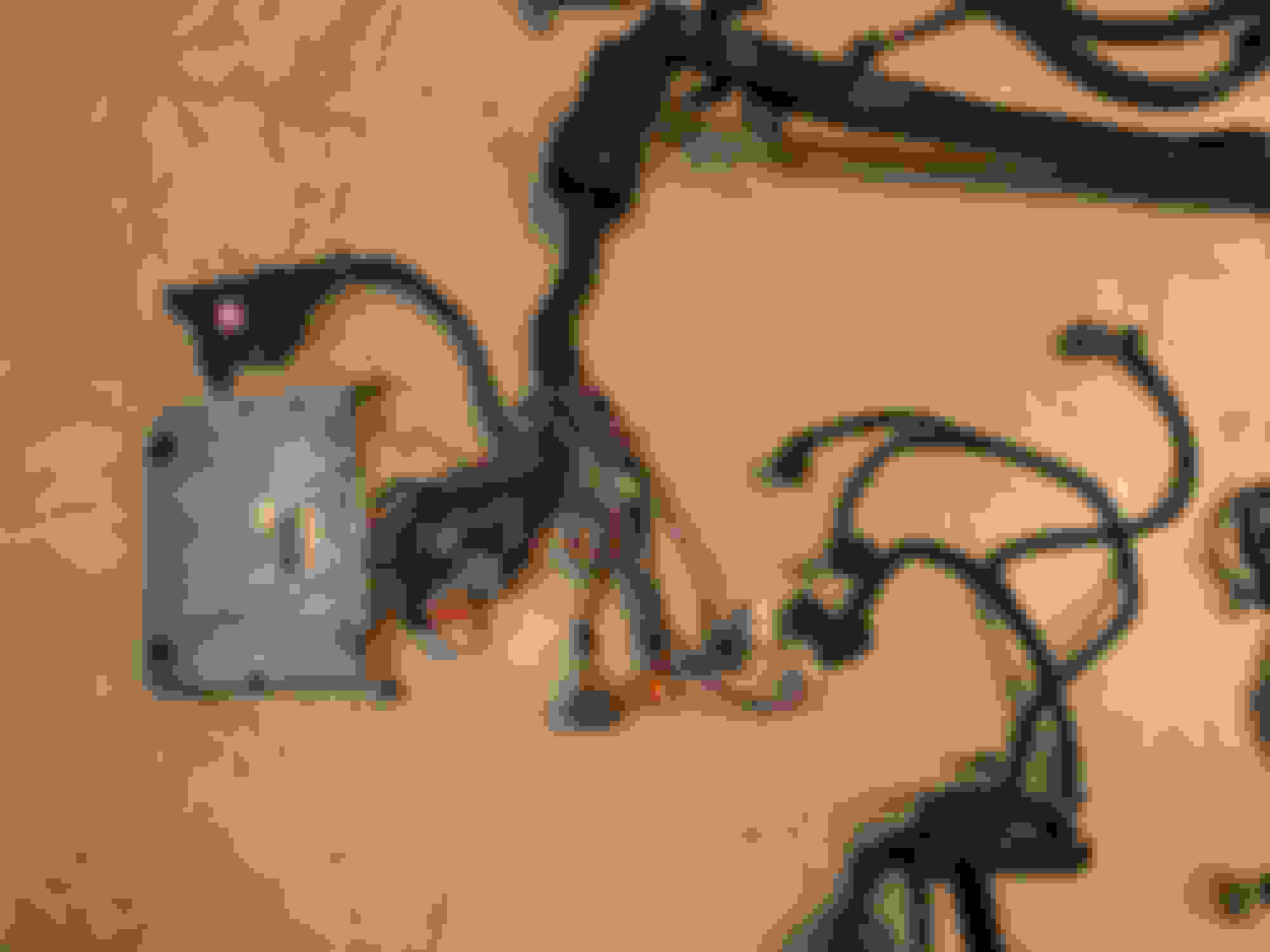
For the 2jzGTE VVTi Harness , I decided to install the igniter near the ECU
You see some loose wires bundled at the center that also goes to the connectors near the ECU. I hate loose wires going around my engine bay so I added extra wires on the harness itself that goes from the engine bay to the inside of the car on the harness that I can use lets say for sensors needed by the aftermarket ecu for safeguards or for gauges sensors.
Added a reverse light connector so this harness could be used for both auto transmission and the manual transmission
Next I will document how you can do a patch harness (once am done with my documentation of the 3 posts above) for those who will want to use an aftermarket ECU. Most aftermarket ECUs do not support the TT auto transmission so you would need to use the aftermarket ECU with conjunction to the stock ECU (this is especially true with IS and GS and other cars whose other functionalities are tied with the stock ECU) .
A patch harness will enable you to use an aftermarket ECU like ProEFI , AEM , Motec , ECUMaster and all the others without modifying your engine harness. That will enable you to be able to use the stock ECU in emergency cases or for trouble shooting which I always prefer.
To give you an idea of the finished products : 2jzGE vvti NA-T engine harness (top) and a 2jzGTE vvti engine harness (bottom)
For the 2jzGE vvti NA-T harness , the original / stock 1998-2000 SC300 harness was barely disturbed. Any needed wiring and pins that didn't exist where taken out from existing wires and pins that where not needed and just moved around .
Since I was using an Aristo VVTi TT auto transmission on this beater car which can easily handle 400-500rwhp with a couple of good transmission oil coolers , majority of the work on the harness were on the transmission connectors
For the 2jzGTE VVTi Harness , I decided to install the igniter near the ECU
You see some loose wires bundled at the center that also goes to the connectors near the ECU. I hate loose wires going around my engine bay so I added extra wires on the harness itself that goes from the engine bay to the inside of the car on the harness that I can use lets say for sensors needed by the aftermarket ecu for safeguards or for gauges sensors.
Added a reverse light connector so this harness could be used for both auto transmission and the manual transmission
Next I will document how you can do a patch harness (once am done with my documentation of the 3 posts above) for those who will want to use an aftermarket ECU. Most aftermarket ECUs do not support the TT auto transmission so you would need to use the aftermarket ECU with conjunction to the stock ECU (this is especially true with IS and GS and other cars whose other functionalities are tied with the stock ECU) .
A patch harness will enable you to use an aftermarket ECU like ProEFI , AEM , Motec , ECUMaster and all the others without modifying your engine harness. That will enable you to be able to use the stock ECU in emergency cases or for trouble shooting which I always prefer.
B1 ECU CONNECTOR (ECU-A Connector on your 1998-2000 SC300 Wiring Diagrams)
1 --> Pin 1 of Injector #3 (**As Is**)
2 --> Pin 1 of Injector #4 (**As Is**)
3 --> Pin 1 of Injector #5 (**As Is**)
4 --> Pin 1 of Injector #6 (**As Is**)
5 --> Pin 2 of VSV1 (**As Is**)
6 --> EMPTY (**As Is**)
7 --> Pin 1 of Electronic Throttle Control ( ETCS-i Motor M-) (**As Is**)
8 --> Pin 2 of Electronic Throttle Control ( ETCS-i Motor M+) (**As Is**)
9 --> Ground Front Intake Manifold (**As Is**)
10--> Pin 1 of Camshaft Sensor (**As Is**)
11 --> Pin 7 of Igniter (**As Is**)
12 --> Pin 6 of Igniter (**As Is**)
13 --> Pin 5 of Igniter (**As Is**)
14 --> EMPTY (**As Is**)
15 --> EMPTY (**As Is**)
16 --> Pin 2 of PS Oil Pressure Switch (**Pull this pin out and leave it EMPTY**)
17 --> Pin 2 of VVTi Solenoid OCV- (**As Is**)
18 --> Pin 1 of VVTi Solenoid OCV+ (**As Is**)
19 --> Pin 4 of Electronic Throttle Control (ETCS-i Clutch CL-) (**As Is**)
20 --> Pin 3 of Electronic Throttle Control (ETCS-i Clutch CL+) (**As Is**)
21 --> Ground Rear Intake Manifold (**As Is**)
22 --> Pin 2 of Camshaft Position Sensor , Pin 2 of Crankshaft Sensor (**As Is**)
23 --> Pin 1 of Crankshaft Position Sensor (**As Is**)
24 --> Pin 6 of IJ1 (**Pull this pin out and leave it EMPTY**)
25 --> Pin 4 of Igniter (**As Is**)
26 --> EMPTY (**As Is**)
27 --> Pin 1 of Knock Sensor 2 (**As Is**)
28 --> Pin 1 of Knock Sensor 1 (**As Is**)
29 --> EMPTY (**As Is**)
30 --> ETCS-i Motor Shielding (grounding inside the ECU) (**As Is**)
31--> Ground Rear Intake Manifold (**As Is**)
B2 ECU CONNECTOR
1 --> Ground Rear Side of Cylinder Head ( **leave this empty**)
2 --> Pin 4 of Accelerator Pedal Position Sensor , Pin 1 of Throttle Position Sensor, Pin 8 of IJ2 (**As Is for the first 2 then remove the connection Pin 8 of IJ2 and make a connection to Pin 3 of MAP**)
3 --> Pin 1 of O2 Sensor 2 (**leave this empty**)
4 --> Pin 1 of O2 Sensor (**As Is**)
5 --> Pin 1 of Injector #1 , Pin 1 of IJ1 (**As Is**)
6 --> Pin 1 of Injector #2 (**As Is**)
7 --> Pin 2 of VSVPRG (**As Is**)
8 --> EMPTY (**As Is**)
9 --> EMPTY (**should go to Pin 2 of Map Sensor**)
10 --> Pin 5 of MAF Sensor (**As Is**)
11 --> Pin 3 of O2 Sensor 2 (**leave this empty**)
12 --> Pin 3 of O2 Sensor (**As Is**)
13 --> Pin 14 of IJ2 (**should go to Pin 5 of PNSW**)
14 --> Pin 2 of Coolant Sensor (**As Is**)
15 --> Pin 2 of Accelerator Pedal Position Sensor (**As Is**)
16 --> Pin 1 of Accelerator Pedal Position Sensor (**As Is**)
17 --> Pin 4 of O2 Sensor , Ground Rear Intake Manifold , (**As Is)
18 --> Pin 2 of MAF Sensor , Pin 1 of Coolant Sensor, Pin 3 of Accelerator Pedal Position Sensor, Pin 4 of Throttle Position Sensor, Pin 7 of Solenoid-ATF Temp Sensor , Pin 10 of IJ2(**As Is for the first 5 then remove the connection Pin 10 of IJ2 and make a connection to Pin 1 of MAP**)
19 --> Pin 3 of MAF Sensor (**As Is**)
20 --> Pin 2 of PNSW (**should go to Pin 4 of PNSW**)
21 --> Pin 3 of PNSW (**should go to Pin 8 of PNSW**)
22 --> Pin 1 of MAF Sensor (**As Is**)
23 --> Pin 2 of Throttle Position Sensor (**As Is**)
24 --> Pin 3 of Throttle Position Sensor (**As Is**)
B3 ECU CONNECTOR
1 --> Pin 5 of Solenoid Connector (**should go to Pin 6 of Solenoid Connector **)
2 --> Pin 10 of Solenoid Connector (**should go to Pin 12 of Solenoid Connector **)
3 --> Pin 5 of Solenoid Connector (** Non Existent on SC300 **) (keep my wiring)
4 --> Pin 2 of Overdrive Speed Sensor (**As Is**)
5 --> Pin 1 of Speed Sensor 2 (**As Is**)
6 --> Pin 11 of Solenoid Connector (** Non Existent on SC300 **) (keep my wiring)
7 --> Pin 4 of Solenoid Connector (**As Is**)
8 --> Pin 3 of Solenoid Connector (**As Is**)
9 --> Pin 2 of Solenoid Connector (**As Is**)
10 --> Pin 1 of Overdrive Speed Sensor (**As Is**)
11 --> Pin 2 of Speed Sensor 2 (**As Is**)
12 --> Pin 9 of IJ2 (**leave this empty**)
13 --> Pin 9 of Solenoid Connector (**should go to Pin 10 of Solenoid Connector **)
14 --> Pin 8 of Solenoid Connector (**should go to Pin 9 of Solenoid Connector **)
15 --> Pin 7 of Solenoid Connector (**should go to Pin 8 of Solenoid Connector **)
16 --> Pin 3 of IK2 (**leave this empty**)
17 --> Pin 1 of ATF Temperature Sensor (**As Is**)
F59 ECU CONNECTOR
1 --> AC Air Condition Control Assembly (*leave this empty)
2 --> Pin 5 of PNSW, Pin 3 of EB1 , Pin 23 of IK2 , Pin 17 if IJ2 (M/T Only) (**should go to Pin 6 of PNSW, Pin 3 of EB1 , Pin 23 of IK2 , Pin 17 if IJ2 (M/T Only)**)
3 --> EMPTY (**should go to Pin 5 of F60, Pin 14 of IJ1**)
4 --> EMPTY (** I used this as my Right Shift Paddle -keep my wiring or leave this empty if you won’t use shift paddles**)
5 --> Pin 11 TC of Data Link Connector D1(**You can keep this empty or keep the wiring for the Diagnostic Port**)
6 --> Pin 7 of IJ2 (**As Is**)
7 --> Pin 6 of IK2 (**As Is**)
8 --> SC300 has this to an O2 sensor (**leave this empty**)
9 --> EMPTY (**As Is**)
10 --> EMPTY (**As Is**)
11 --> Pin 1 of IJ2 (**As Is**)
12 --> Pin 21 of IK1 trans PWR switch (*leave this empty*)
13 --> Pin 2 of EB-1 (**As Is**)
14 --> EMPTY (** I used this as my Left Shift Paddle - keep my wiring or leave this empty if you won’t use shift paddles**)
15 --> EMPTY (**As Is**)
16 --> Pin 8 of PNSW (**should go to Pin 2 of PNSW**)
17 --> Pin 9 of PNSW (**should go to Pin 7 of PNSW**)
18 --> EMPTY (**As Is**)
19 --> EMPTY (**As Is**)
20 --> outputs a TACH signal (**leave this empty**)
21 --> Pin 18 of IK2 shift lock ecu (**leave this empty**)
22 --> EMPTY (**As Is**)
23 --> Pin 2 of IJ2 (**As Is**)
24 --> EMPTY (** As Is**)
25 --> EMPTY (** As Is**)
26 --> Pin 11 of IJ1 (**should go to Pin 1 of the PNSW**)
27 --> Pin 18 of IK2 RSPD (**leave this empty**)
28 --> Pin 6 of IK1 (**leave this empty**)
F60 ECU CONNECTOR
1 --> Pin 4 of EB1 (**As Is**)
2 --> Pin 7 of IK1 (** leave this empty**)
3 --> Pin 17 of IK2 (** leave this empty**)
4 --> Pin 8 of IJ1 (**As Is**)
5 --> Pin 14 of IJ1 , Pin 3 of F59 (keep my wiring)
6 --> Pin 9 of IK2 (**As Is**)
7 --> Pin 13 of IJ1 (**As Is**)
8 --> Pin 16 of F60, Pin 3 of EB2 , Pin 12 of IJ1 (**As Is**)
9 --> Pin 11 of IJ2 (**As Is**)
10 --> Pin 8 of EB1 (**As Is**)
11 --> Pin 18 of IK1 (**As Is**)
12 --> EMPTY (**As Is**)
13 --> TRC+ (**leave this empty for those without traction control**)
14 --> ENG+ (**leave this empty for those without traction control**)
15 --> NEO+ (**leave this empty for those without traction control**)
16 --> Pin 3 of EB2 , Pin 12 of IJ1, Pin 8 of F60 (**As Is**)
17 --> EMPTY (**As Is**)
18 --> EMPTY (**As Is**)
19 --> EMPTY (**As Is**)
20 --> TRC- (**leave this empty for those without traction control**)
21 --> ENG- (**leave this empty for those without traction control**)
22 --> Pin 3 of IJ2 (**As Is**)
EB1 Connector
1 --> Pin 4 of AC Compressor(**As Is**)
2 --> Pin 13 of F59 (**As Is**)
3 --> Pin 5 of PNSW , Pin 2 of F59 (STA) , Pin 23 of IK2 , Pin 17 of IJ2 (M/T only) (** should go to Pin 6 of PNSW , Pin 2 of F59 (STA) , Pin 23 of IK2 , Pin 17 of IJ2 (M/T only)**)
4 --> Pin 1 of F60 (**As Is**)
5 --> Empty (**As Is**)
6 --> Pin 23 of Data Link Connector 1 D1 (**You can keep this empty or keep the wiring for the Diagnostic Port**)
7 --> Pin 1 of II1 , Pin 1 of AC Compressor (**As Is**)
8 --> Pin 10 of F60 (**As Is**)
EB2 Connector
1 --> Starter Solenoid (**As Is**)
2 --> Empty
3 --> Pin 12 of IJ1 , Pin 8 of F60 , Pin 16 of F60 (**As Is**)
IK1 Connector
1 --> Ground Intake Manifold Front Side ((**As Is**)plus Pin 1 of Power Steering Oil Pressure Switch))
2 --> EMPTY (**As Is**)
3 --> EMPTY (**As Is**)
4 --> EMPTY (**As Is**)
5 --> EMPTY (**As Is**)
6 --> Pin 28 PWRL (**should go to Pin 2 of the Speed Sensor 1**)
7 --> Pin 2 SND (** should go to Pin 3 of the Speed Sensor 1 **)
8 --> Pin 8 of Igniter , Pin 1 of Short Connector
9 --> Pin 1 of Water Temp Sender Gauge , Pin 7 of Short Connector (**As Is**)
10 --> Pin 11 of Data Link Connector 1 D1 (**You can keep this empty or keep the wiring for the Diagnostic Port**)
11 --> Pin 8 of PNSW (**should go to Pin 2 of PNSW , Pin 16 of F59**)
12 --> Pin 7 of PNSW (**should go to Pin 1 of PNSW , Pin 26 of F59
13 --> Pin 10 of PNSW (**should go to Pin 5 of PNSW , Pin 13 of B2 ECU Connector**)
14 --> Pin 9 of PNSW (**should go to Pin 7 of PNSW , Pin 17 of F59**)
15 --> Ground Intake Manifold Rear Side (**As Is**)
16 -->Pin 2 of PNSW (**should go to Pin 4 of PNSW , Pin 20 of B2 ECU Connector**)
17 -->Pin 3 of PNSW(**should go to Pin 8 of PNSW , Pin 21 of B2 ECU Connector**)
18 --> Pin 11 of F60 (**As Is**)
19 --> Ground Intake Manifold (**As Is**)
20 --> Pin 1 of Oil Pressure Switch (**As Is**)
21 --> Pin 12 PWR (**leave this empty**)
22 --> Pin 20 (**leave this empty**)
23 --> Pin 1 of Oil Level Switch Sensor (**As Is**)
IK2 Connector
1 --> Pin 24 OX2B (**leave this empty**)
2 --> Pin 22 of Data Link Connector 1 D1 (**You can keep this empty or keep the wiring for the Diagnostic Port**)
3 --> Pin 16 PI (**leave this empty**)
4 --> Pin 22 of F84 ECU Connector (**leave this empty-ECU should be no immobilizer**)
5 --> Pin 21 of F84 ECU Connector (**leave this empty-ECU should be no immobilizer**)
6 --> Pin 7 of F59(**As Is**)
8 --> Pin 25 HT2B(**leave this empty**)
9 --> Pin 6 of F60 (**As Is**)
10 -->Pin 5 of Data Link Connector 1 (**You can keep this empty or keep the wiring for the Diagnostic Port**)
11 --> EMPTY (**As Is**)
12 --> EMPTY (**As Is**)
13 --> EMPTY (**As Is**)
14 --> EMPTY (**As Is**)
15 --> Pin 23 of F84 ECU Conector (**leave this empty-ECU should be no immobilizer**)
16 -->Pin 9 ECM(**leave this empty**)
17 --> Pin 3 SMSW(**leave this empty**)
18 --> Pin 27 RSPD for shift lock (**leave this empty**)
19 --> EMPTY (**As Is**)
20 --> EMPTY (**As Is**)
23 --> Pin 5 of PNSW , Pin 3 of EB1 , Pin 2 of F59 (STA) , Pin 17 of IJ2 (M/T only) (**should go to Pin 6 of PNSW , Pin 3 of EB1 , Pin 2 of F59 (STA) , Pin 17 of IJ2 (M/T only)**)
24 --> Ground Front Side of Intake Manifold (**As Is**)
25 --> Pin 16 of Data Link Connector 1 D1 (**You can keep this empty or keep the wiring for the Diagnostic Port**)
IJ1 Connector
1 --> Pin 1 of Injector 1 ,Pin 5 of B2 ECU Connector (**As Is**)
2 --> Pin 2 of II1 , Pin 2 of the VSV Heater Valve (**As Is**)
3 --> Pin 3 of Short Connector , Pin 2 of Injectors 2 / 4 / 5 / 6 (**As Is**)
4 --> Pin 2 of Theft Deterrent Horn (**As Is**)
5 --> Pin 4 of MAF Sensor, Pin 2 of O2 Sensor , Pin 1 of VSV-PRG , Pin 1 of VSV1-ACIS, Pin 12 B+Data Link Connector D1 (**As Is**)
6 --> Pin 6 of PNSW, Pin 24 of B1 ECU-A Connector (**should go to Pin 9 of PNSW**)
7 --> Pin 5 of Short Connector , Pin 1 of Coils 1 / 2 / 3 , Pin 1 of Noise Filter , Pin 9 of Igniter , Pin 2 of Injectors 1 / 3 (**As Is**)
8 --> Pin 4 of F60 (DI) (**As Is**)
9 --> Pin 1 of Theft Deterrent Horn (**As Is**)
10 -->Pin 4 of PNSW (** should go to Pin 3 of PNSW ,Pin 1 of the Speed Sensor 1 , Pin 2 of the Reverse Light Switch(M/T Only) **)
11 --> Pin 26 of F59 (**leave this empty–ECU pin used by VVTi TT Auto Trans**)
12 --> Pin 3 of EB2 , Pin 8 of F60 , Pin 16 of F60 (**As Is**)
13 --> Pin 7 of F60 (**As Is**)
14 --> Pin 5 of F60 (FPC) (**As Is**)
Note about : IJ1-3 & IJ1-7
They are connected internally so whatever is connected to IJ1-3 technically is connected to IJ1-7
IJ2 Connector
1 --> Pin 11 of F59 (** As Is**)
2 --> Pin 23 of F59 (** As Is**)
3 --> Pin 22 of F60 (** As Is**)
4 --> Pin 13 TBP (**leave this empty **)
5 --> Empty (** As Is**)
6 --> Pin 1 of PPS Solenoid (** As Is**)
7 --> Pin 6 of F59 (** As Is**)
8 -->Pin 1 of TPS , Pin 4 of APPS (**leave this empty**)
9 --> Pin 12 of B3 ECU Connector (**leave this empty**)
10 --> Pin 2 of MAF , Pin 1 of Coolant Temp Sensor , Pin 4 of TPS , Pin 3 of APPS (**leave this empty**)
11 --> Pin 9 of F60 (** As Is**)
12 --> Pin 10 of F84 ECU-F Connector (**leave this empty-ECU should have no immobilizer**)
13 --> Pin 18 of F59 ECU-D Connector (**leave this empty**)
14 --> Pin 13 of B2 ECU-B Connector (**leave this empty–ECU pin used by VVTi TT Auto Trans**)
15 --> Empty (** As Is**)
16 --> Pin 2 of PPS Solenoid (** As Is**)
II1 Connector
1 --> Pin 1 of the AC Connector , Pin 7 of EB1 (**As Is**)
2 --> Pin 2 of the VSV Heater Valve, Pin 2 of IJ1 (**As Is**)
3 --> EMPTY (**As Is**)
4 --> Pin 2 of the AC Connector (**As Is**)
5 --> Should go to the AC request Pin of the ECU but the Aristo 2jzgtte VVTi has none. Use a relay to activate compressor.
6 --> EMPTY (**As Is**)
7 --> Pin 1 of the VSV Heater Valve (**As Is**)
8 --> EMPTY (**As Is**)
9 --> EMPTY (**As Is**)
10 --> EMPTY (**As Is**)
11 --> EMPTY (**As Is**)
12 --> EMPTY (**As Is**)
AC COMPRESSOR (You will need to replace the Aristo 3 pin connector with that of the 4 pin SC or MKIV , the aristo vvti has a different connector)
1 --> Pin 1 of II1 , Pin 7 of EB-1 (**As Is**)
2 --> Pin 4 of II1 (**As Is**)
3 --> Empty (**As Is**)
4 --> Pin 1 of EB-1 (**As Is**)
ACCELERATOR PEDAL POSITION SENSOR
1 --> Pin 16 of B2 ECU Connector (**As Is**)
2 --> Pin 15 of B2 ECU Connector (**As Is**)
3 --> Pin 18 of B2 ECU Connector , Pin 1 of Coolant Sensor, Pin 2 of MAF , Pin 4 of TPS , Pin 7 of Solenoid - ATF Temp Sensor , Pin 10 of IJ2 (** As Is for the first 5 and remove connection to Pin 10 of IJ2 and make a connection straight to Pin 1 of the Map sensor**)
4 -->Pin 2 of B2 ECU Connector , Pin 1 of TPS , Pin 8 of IJ2 (**As Is for the first two and remove the connection to Pin 8 of IJ2 and make a connection straight to Pin 3 of Map Sensor**)
COOLANT SENSOR
1 --> Pin 18 of B2 ECU Connector , Pin 2 of MAF , Pin 4 of TPS , Pin 3 of APPS, Pin 7 of Solenoid- ATF Temp Sensor , Pin 10 of IJ2 (** As Is for the first 5 and remove connection to Pin 10 of IJ2 and make a connection straight to Pin 1 of the Map sensor**)
2 --> Pin 14 of B2 ECU Connector (**As Is**)
CRANK POSITION SENSOR
1 --> Pin 23 of B1 ECU Connector (**As Is**)
2 --> Pin 22 of B1 ECU Connector (**As Is**)
ELECTRONIC THROTTLE CONTROL CLUTCH(ETCS-i)
1 --> Pin 7 of B1 ECU Connector (**As Is**)
2 --> Pin 8 of B1 ECU Connector (**As Is**)
3 --> Pin 20 of B1 ECU Connector (**As Is**)
4 --> Pin 19 of B1 ECU Connector (**As Is**)
HEATER VALVE
1 --> Pin 7 of II1 (**As Is**)
2 --> Pin 2 of II1 , Pin 2 of IJ1 (**As Is**)
IGNITION COIL #1 (Front of Engine)
1 --> Pin 7 of IJ1 (**As Is**)
2 --> Pin 1 of Igniter (C2-) (**As Is**)
MAF SENSOR
1 --> Pin 22 of B2 ECU Connector (**As Is**)
2 --> Pin 18 of B2 ECU Connector , Pin 1 of Coolant Sensor, Pin 3 of Accelerator Pedal Position Sensor, Pin 4 of TPS , Pin 7 of Solenoid - ATF Temp Sensor , Pin 10 of IJ2 (** As Is for the first 5 and remove connection to Pin 10 of IJ2 and make a connection straight to Pin 1 of the Map sensor**)
3 --> Pin 19 of B2 ECU Connector (**As Is**)
4 --> Pin 5 of IJ1 , Pin 2 of O2 Sensor , Pin 1 of VSV-PRG , Pin 1 of VSV1-ACIS
5 --> Pin 10 of B2 ECU Connector (**As Is**)
MAP SENSOR
1 --> Pin 18 of B2 ECU Connector , Pin 2 of MAF Sensor, Pin 1 of Coolant Sensor, Pin 3 of Accelerator Pedal Position Sensor ,Pin 4 of TPS , Pin 7 of Solenoid - ATF Temp Sensor
2 --> Pin 9 of B2 ECU Connector
3 --> Pin 2 of B2 ECU Connector , Pin 4 of Accelerator Pedal Position Sensor , Pin 1 of TPS
Noise Filter
1 --> Pin 7 of IJ1 , Pin 9 of Igniter , Pin 1 of Coils 1 / 2 / 3 (**As Is**)
2 --> Ground Rear Side of Cylinder Head (**As Is**)
OIL LEVEL SWITCH
1 --> Pin 23 of IK1 (**As Is**)
2 --> Ground Rear Side of Intake Manifold (**As Is**)
OXYGEN SENSOR
1 --> Pin 4 of B2 ECU Connector (**As Is**)
2 --> Pin 4 of MAF 4 , Pin 5 of IJ1 , Pin 2 of O2 Sensor , Pin 1 of VSV-PRG , Pin 1 of VSV1-ACIS (**As Is**)
3 --> Pin 12 of B2 ECU Connector (**As Is**)
4 --> Pin 17 of B2 ECU Connector and to the Rear Ground connector on the intake manifold (E1 = ECU Ground) (**As Is**)
PARK / NEUTRAL SWITCH ( You will have to replace the 10 pin PNSW connector of the SC300 with the 9 pin PNSW connector of the Aristo 2jzgte VVTi )
1 --> EMPTY
2 --> Pin 16 of IK1 , Pin 20 of B2 ECU Connector (**should go to Pin 4 of PNSW, Pin 16 of IK1, Pin 20 of B2 ECU Connector**)
3 --> Pin 17 of IK1 , Pin 21 of B2 ECU Connector (**should go to Pin 8 of PNSW, Pin 17 of IK1, Pin 21 of B2 ECU Connector**)
4 --> Pin 10 of IJ1 (**should go to Pin 3 of the PNSW **)
5 --> Pin 23 of IK2 , Pin 3 of EB1 , Pin 2-STA of F59 (**should go to Pin 6 of PNSW, Pin 23 of IK2 , Pin 3 of EB1 , Pin 2-STA of F59**)
6 --> Pin 6 of IJ1 , Pin 24-NSW of F59 (**should go to Pin 9 of PNSW, Pin 6 of IJ1**)
7 --> Pin 12 of IK1 (**should go to Pin 1 of PNSW , Pin 26 of F59 (Pin 26 of F59 currently goes to Pin 11 of IJ1… move it here ) , Pin 12 of IK1 **)
8 --> Pin 11 of IK1 , Pin 16 of F59(**should go to Pin 2 of PNSW, Pin 16 of F59 , Pin 11 of IK1**)
9 --> Pin 14 of IK1 , Pin 17 of F59 (**should go to Pin 7 of PNSW, Pin 17 of F59, Pin 14 of IK1**)
10 --> Pin 13 of IK1 (**should go to Pin 5 of PNSW , Pin 13 of IK1, Pin 13 of B2 ECU Connector(Pin 13 of B2 currently goes to Pin 14 of IJ2.. move it here) **)
PROPORTIONS POWER STEERING (PPS)
1 --> Pin 6 of IJ2 (**As Is**)
2 --> Pin 16 of IJ2 (**As Is**)
SOLENOID (Replace the SC300 10 pin solenoid connector with the Aristo VVTi 12 pin solenoid connector)
1 --> Pin 17 of B3 ECU Connector (**As Is**)
2 --> Pin 9 of B3 ECU Connector (**As Is**)
3 --> Pin 8 of B3 ECU Connector (**As Is**)
4 --> Pin 7 of B3 ECU Connector (**As Is**)
5 --> Pin 1 of B3 ECU Connector (**should go to Pin 3 of B3 ECU Connector-wire to ECU should be added since it doesn't exist now**)
6 --> Pin 18 of B2 ECU Connector (**should go to Pin 1 of B3 ECU Connector**)
7 --> Pin 15 of B3 ECU Connector (**should go to Pin 18 of B2 ECU Connector**)
8 --> Pin 14 of B3 ECU Connector (**should go to Pin 15 of B3 ECU Connector**)
9 --> Pin 13 of B3 ECU Connector (**shoud go to Pin 14 of B3 ECU Connector**)
10 --> Pin 2 of B3 ECU Connector (**should go to Pin 13 of B3 ECU Connector**)
11 --> Non Existent on SC300 (**should go to Pin 6 of B3 ECU Connector -wire to ECU should be added since it doesn't exist now**)
12 --> Non Existent on SC300 (**should go to Pin 2 of B3 ECU Connector**)
THEFT DETERRENT HORN
1 --> Pin 9 of IJ1 (**As Is**)
2 --> Pin 4 of IJ1 (**As Is**)
THROTTLE POSITION SENSOR
1 --> Pin 2 of B2 ECU Connector , Pin 4 of Accelerator Pedal Position Sensor , Pin 8 of IJ2 (**As Is for the first two and remove the connection to Pin 8 of IJ2 and make a connection straight to Pin 3 of Map Sensor**)
2 --> Pin 23 of B2 ECU Connector (**As Is**)
3 --> Pin 24 of B2 ECU Connector (**As Is**)
4 --> Pin 18 of B2 ECU Connector , Pin 1 of Coolant Sensor, Pin 3 of Accelerator Pedal Position Sensor, Pin 2 of MAF , Pin 7 of Solenoid - ATF Temp Sensor , Pin 10 of IJ2 (** As Is for the first 5 and remove connection to Pin 10 of IJ2 and make a connection straight to Pin 1 of the Map sensor**)
VSV1-ACIS
1 --> Pin 5 of IJ1 , Pin 4 of MAF Sensor, Pin 2 of O2 Sensor , Pin 1 of VSV-(**As Is**)
2 --> Pin 5 of B1 ECU Connector (**As Is**)
VSV-PRG
1 --> Pin 5 of IJ1 , Pin 4 of MAF Sensor, Pin 2 of O2 Sensor , Pin 1 of VSV1-ACIS (**As Is**)
2 --> Pin 7 of B2 ECU Connector (**As Is**)
Post 4314 , which is the previous post, will have the complete Pin Outs for the 1998-2000 SC300 engine harness conversion ..for a VVTi 2jzGE-NAT or a 2jzGTE VVTi swap project . The conversion harness assumes that you are using an Aristo 2jzgte VVTi ECU with an Aristo VVTi 2jzgte TT transmission.
Hope you all save that more than $1000 for a swap harness by doing it yourself and be able to use it for go fast goodies . ENJOY !
Damn, Gerry! Looking good so far! That engine is about to get a new lease on life after you're done keeping it pumping iron in the gym!
These pinouts are great! Making it much easier for all the late model SC300 owners
Sorry if I have asked this before but since you are using the GE VVT-i head and throttle body, to control that with a Toyota ECU you're using an Aristo 2JZ-GTE VVT-i ECU, right?
I'm definitely in agreement with you on your "not many cars on the road have 400whp" comment. I've noticed this too-- few people suspect anything from an unassuming looking car, even when it's an SC. Even 350-400whp in a 3500-3600 pound car is a power to weight ratio only in so many cars on the road most of the time. This one will be a sleeper near semi daily driver for you I'll bet
You know me , I don't play around . When I want things , they are done quick . I haven't dropped the engine on the bay though cause I don't have yet the right sized turbo I wanted and the treadstone manifold...still looking for the right deal for a small sized turbo so it can be very responsive . Maybe I will drop it this coming week even without to just be able to move the car around. I don't think I can do any painting on that engine anytime soon due to the cold weather so screw the painting. I am not waiting for summer just to paint the engine and then get the car running. Engine is clean anyway.
yes Craig ....the wiring above assumes that you are using an Aristo 2jzgGTE VVTi ECU with its TT vvti auto transmission.. To use another ecu like an aftermarket ecu , you can always use a jumper harness and be on standalone . If you want to use the auto transmission functionality of the stock ecu since many aftermarket ecu do not have that functionality , you can make a jumper harness piggy backing stock ecu with aftermarket ecu . The stock TT transmission can easily handle 450rwhp with good coolers.
If you are on a manual trans then all the TT transmission harness work in which the solenoid and park neutral switch connectors are replaced isn't necessary . Also, the wiring harness IS NOT ONLY for late model SCs from 98-2000. Harness can be used by1992-2000 SCs. In fact, I did the same harness for a friend who is local and a forum member . He had a 1993 SC to start with. He now is shooting for 800rwhp with a Haltech Elite ecu. If you have an SC from 1992-1997 , there are very minor mods you need to do on your car.... really minor .
What I am saying is , starting with a 1998-2000 SC300 engine harness , you don't have to do a lot of work on that stock harness and better , you don't have to spend tons of money on getting an engine harness done to do a 2jzGE vvti NAT or 2jzGTE VVTi swap project regardless of what year is your SC.
Now that the cat is out of the bag, the damn 1998-2000 SC300 engine harness will start getting harder to find and be pricier now.. hahaha
Craig - that 2jGE vvti NAT harness is going on a 1993 original 5 speed SC300 . For now it will be on an auto transmission because of my power goals. The W58 on it right now won't last long at 400-450rwhp of same torque so no point of using it . As mentioned , I just need to do some minor modifications on that car's wiring.. not really much. That will prove what I said about the said harness can be used by any 1992-2000 SC.
SC on the left is the 1993. Since it has a full black interior , am thinking of getting it painted Blue ... maybe RSP ??? but am not a fan of that color. I am more leaning to the Speedway Blue 8P1 of the Toyota Tacoma. But whatever shade of blue , it will be blue nevertheless so I will have a Red , White and Blue SC at different power levels. That beige SC at 940rwhp will definitely be painted white . The red will have the highest HP among them all since it has a stroker motor. That black original 1997 SC300 5 speed (1 of 120) will stay stock if it is staying with me which I doubt. All I need is someone whose interest I really see and I will be giving him a good deal on it. Though I want a fair deal not a tire kicker's price , tons of them . They want it free .... lol. Am willing to let go of it lower than what these stock 1997 SC300 5 speeds are being sold now .
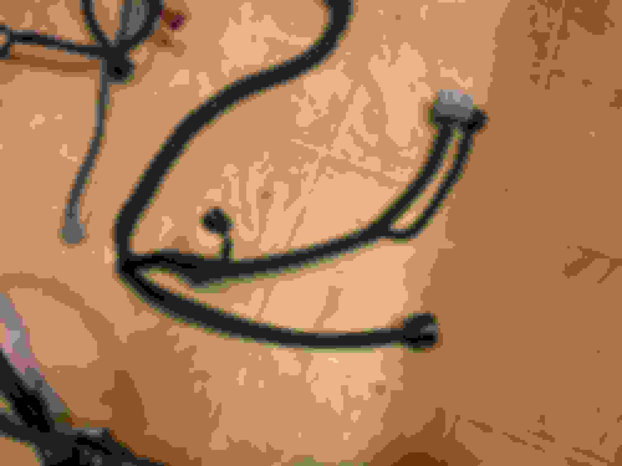
BTW , I would like to emphasize that if you are not totally removing any unused wire / pin , you would have to heat shrink them since the other end of a certain pin might still be connected to a component or live wire. Below you see what I did on mine. I just finished installing that wire into the engine and later mate the transmission into the engine and I guess this week drop it into the engine bay.
I ran into a vvti issue I think you might know the answer to. *edit* apparently I have an early 2jz block
Since you have a half dozen 2jzge's over there you are likely the best person to ask lol.
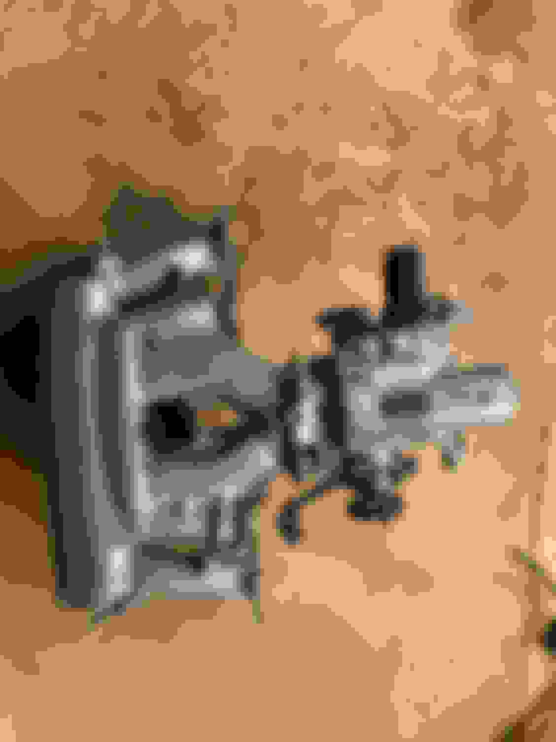
I should have a 95 supra n/a block, and I do have an oil pressure sensor where the vvti oil feed normally goes on the block.
When I remove the oil pressure sensor, the block has the standard 1/8 pipe thread for an oil pressure sensor.
Now the 2jzgte vvti oil feed line I got has a much larger bolt, that seems to be a 3/8 pipe thread.
when I look up pictures online, it seems that some blocks have a larger opening (im guessing the 3/8) and an adapter for the pressure sensor (guessing down to 1/8).
I also noticed the bolt going into the block for the vvti feed line has as check valve in it, so if I replace the line I will need a check valve.
I ordered an adapter from 1/8 to 3/8 and am going to try and use that to adapt the stock feed line, as drilling the block at this point would be a hassle.
Am I missing something cause I haven't heard of anyone talk about this other than that there is a spot for the vvti oil feed, but it doesn't seem to be the right size.
It seems my options is to use adapters to make the stock line/bolts fit or..
make a new line with adapters/AN fittings/banjos and incorporate a check valve if that makes sense.
pic of said threaded hole with pressure sensor removed, see bottom left
It has the same size threads as the factory IS300 union bolt you can see on the right as the pressure sensor screws into both.
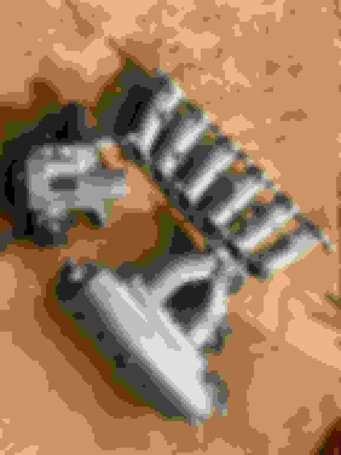
Another concern is that if I adapt the stock line with adapters, it will need to clear the a/c compressor which seems like it can.
Not to mention I am not 100% sure the oil voume will be enough, but looking at the inside of the check valve on the banjo bolt the oil passage is actually pretty small.
Notice the pressure sensor has that adapter to the bigger size.
Seems like I need the reverse of that.
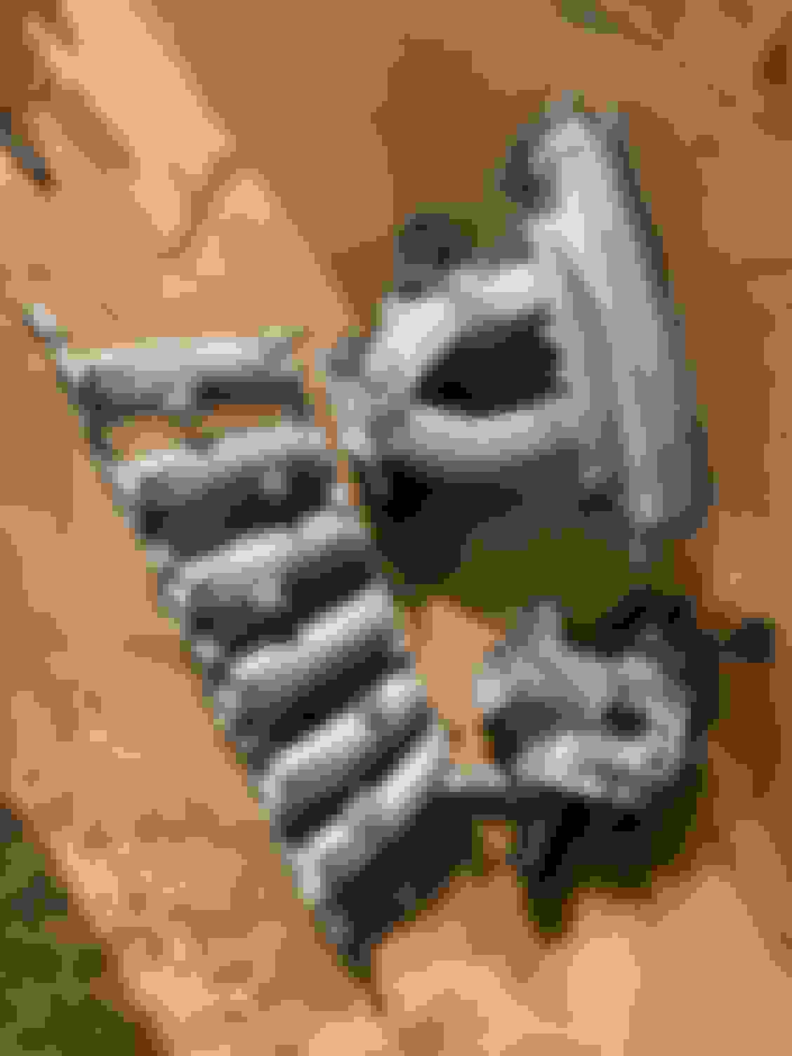
I am starting to think maybe I have a pre 95 block that was mid year 95 or something.
after looking alot closer, it seems the bigger vvti hole is slightly lower on the block too.
I saw the oil sensor and assumed I was good until I tried to put it all together
*edit* It turns out I do have a pre 95 style block, and do need an adapter which the only one I can find is sold by PHR so I ordered one to use as I read on supra forums that it works.
I think I found the answer out.. apparently PHR has an adapter fitting for early blocks that goes from the smaller fitting to the larger fitting, and they said just bend the line a little. So apparently I have an early block, and anyone else who has that issue you need the adapter fitting. I am not sure if theirs is different than the one I ordered, but will probably get one just in case.
 01-07-19, 03:29 AM


 . Remember not a lot of car out there will have 400rwhp , so in a way you can fool around with almost every car on the street
  .
.