When you click on links to various merchants on this site and make a purchase, this can result in this site earning a commission. Affiliate programs and affiliations include, but are not limited to, the eBay Partner Network.
It's projects like this that keep people like me motivated (both mentally and financially) to continue my own project. Keep up the good work, looks awesome!
Thanks guys! Sorry for the delay in posts. There is a lot of catchup in this one.
Where we last left off I had some learning to do with the oil pump. Since that first try I redid the FIPG seal and found all the correct bolts. It turns out I had ordered them twice! I was thrown off because I was actually trying to use the wrong holes for the long ones. I'm not sure how I had thought that was right but it was late. Anyway, the finished oil pump install.
(Also, the water pump did get its remaining two bolts installed after this picture was taken)
Next...
Oil Pan Installation
A few months prior to this I had already done the oil pan turbo drain conversion since this pan was from an SC300. That process is covered in earlier pages. The pan had also been sonic cleaned by my first machine shop which got almost all the grime and remaining gasket removed. Nice and clean.
First things first, I lubed up the iron block side turbo oil drain gasket with Lucas semi-synthetic assembly lube (pictured below, P/N 90301-A0032). This is a VERY important step. You don't want to forget this.
Now we get onto applying the FIPG gasket to the lower oil pan. This is outlined in the Supra MKIV TSRM EG-374 under "LUBRICATION SYSTEM".
The process is the same style as with the oil pump but there is much more to do. The manual states you have five minutes to install the parts (presumably after having applied the first bead to the pan as guided). I didn't time myself but I had no issue. The guide dowels get everything centered.
I don't have the bolt part numbers. I bought a full 2JZ oil pan bolt kit from Driftmotion for this. Everything was there and for once there was no hunting down every thing from Toyota.
The factory 12mm bolts require 15 lb-ft while the large factory 14mm bolts in the open lower sump area require 29 ft-lbs. The Driftmotion bolts were, I think, one size difference in one case. Maybe 13mm for the smaller ones instead of 12mm?
WHOOPS... I DIDN'T REALIZE I HAD TO DO THAT FIRST...
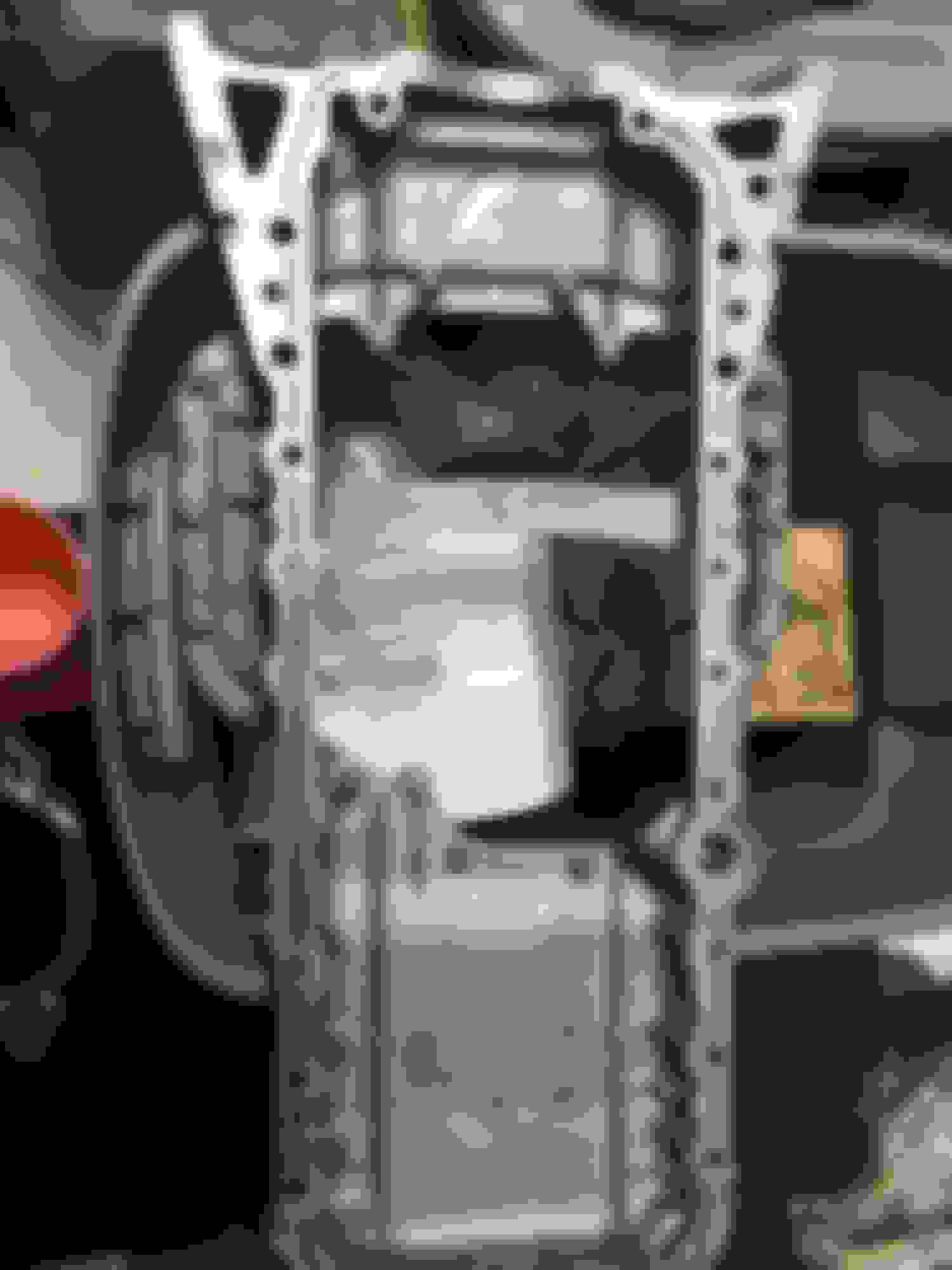
After a job well done I thought I began to focus on the oil pan scatter/baffle and pickup when I noticed... the rear of the engine where the main seal goes seemed awfully empty. Empty enough to drive a bunch of Hot Wheels cars right through it. There is an aluminum rear plate which goes on the back that surrounds the rear main seal and keeps the crankcase airtight that was missing.
Thankfully I had the random foresight to buy this a few days earlier thinking it would go on later in the process. In fact, it had arrived in the mail that very day but I had not realized it was necessary to install first since this section of the TSRM hadn't covered it.
Unfortunately with the FIPG seal already curing on the upper oil pan this meant... you guessed it... I had to remove EVERYTHING and start over. Sigh.
Here is a picture of the rear of the crankshaft without that important aluminum cover and the main seal installed.
So... removing the pan and getting to some VERY careful cleaning of the underside of the block. Now if you think I had been careful cleaning off fresh FIPG from the oil pump and block mating surfaces, that did not compare to the time and slow care I gave to this. Getting random scrapings of FIPG into the crank galley would be extremely bad. I took at least three hours using alcohol on disposable shop towels, a plastic non-marring gasket scraper and my nylon gloved fingers taking up each and every spec and strip of FIPG from large strands to tiny little specks. I didn't dare rush this process for fear of contaminating the crankcase.
And now the upper oil pan needs to be cleaned again. Since this was out of the engine I could afford to go a bit faster and make a mess. Afterward I still had to go through every nook and cranny to make sure every speck of FIPG debris had been removed from every surface and passage.
Rear crank/main seal retainer plate installation
The rear crankshaft/seal retainer plate is P/N 11381-46010. It uses six (6) bolts P/N 91511-B0614. And then an application of FIPG in a "U" shape before aligning it onto the dowel pins on the block.
Those six bolts require 52 inch-lbs each. I used the Harbor Freight 1/4" socket lb-in torque wrench for this, however two of those bolts were very difficult to get to even with the short height of that wrench and socket on this stand. I tried my best to gauge what I felt the wrench torque was through my hand and tried to duplicate it with a hand wrench.
Finally, I went through the entire upper pan installation process all over again, this time permanently.
Though the TSRM did not state any specific torque pattern for the upper oil pan I still invented my own and at least tried to zig zag around on alternate sides as the pan tightened down onto the FIPG and as each bolt gradually reached its required torque load. An even seating would be more ideal, I thought.
The final result, with that plate installed and the rear main seal installed (not so easy with little clearance but I did it after many tries).
And a little video tutorial I came across that helped familiarize me with how the rear main seal goes in. Surprisingly it can go in TOO FAR which is what makes the perfectly flat alignment so difficult in such a tight space while on the engine stand.
Next, the lower oil pan (sump) installation, oil pickup/strainer and baffle
Before getting into this part I had to do a little more TLC. The oil pickup was in good shape but it had a bit of very, very minor grime or surface rust on it despite being sonic cleaned. So... I got a little 280 grit sandpaper I had laying around, took it into the workshop and carefully scrubbed what I deemed as any trouble areas. The end result wasn't brand new looking but was now free from any concerning surface rust that I'd rather not have had in the engine oil. I wiped and cleaned all of the surfaces several times thoroughly to ensure no random metal and oxidation dust were left.
Before...
Clean enough.
Next, with all of this work to completely rebuild an engine from scratch I wanted to paint the oil pan.
One lip edge was ever so slightly bent up and so I put the pan on a flat wooden surface facing down and took a rubber mallet to it to gently bang it flat again. I didn't overdo each blow for fear of unnecessarily distorting the rest of the oil pan. This took maybe 30 minutes with periodic test fits onto the mounted upper oil pan.
Then the painting process.
I used, I think, 100 grit sandpaper to score up and remove as much of the original aged and scratched up paint as possible. I think I followed with 320 grit which is about the highest grit I had on hand. I used VHT high temperature engine spray paints. Primer first, then VHT Black, then a coat of VHT Satin Clear. It added a day of work waiting off and on for each coat of paint to dry and also take care of any edges I missed. A little wad of painter's tape was stuffed into the oil pan drain area to keep the threads clean.
The result turned out very nice but even after all that work I found it was easy to get a scratch on the well dried coats of paint and clear. Oh well. It still looks much better than before!
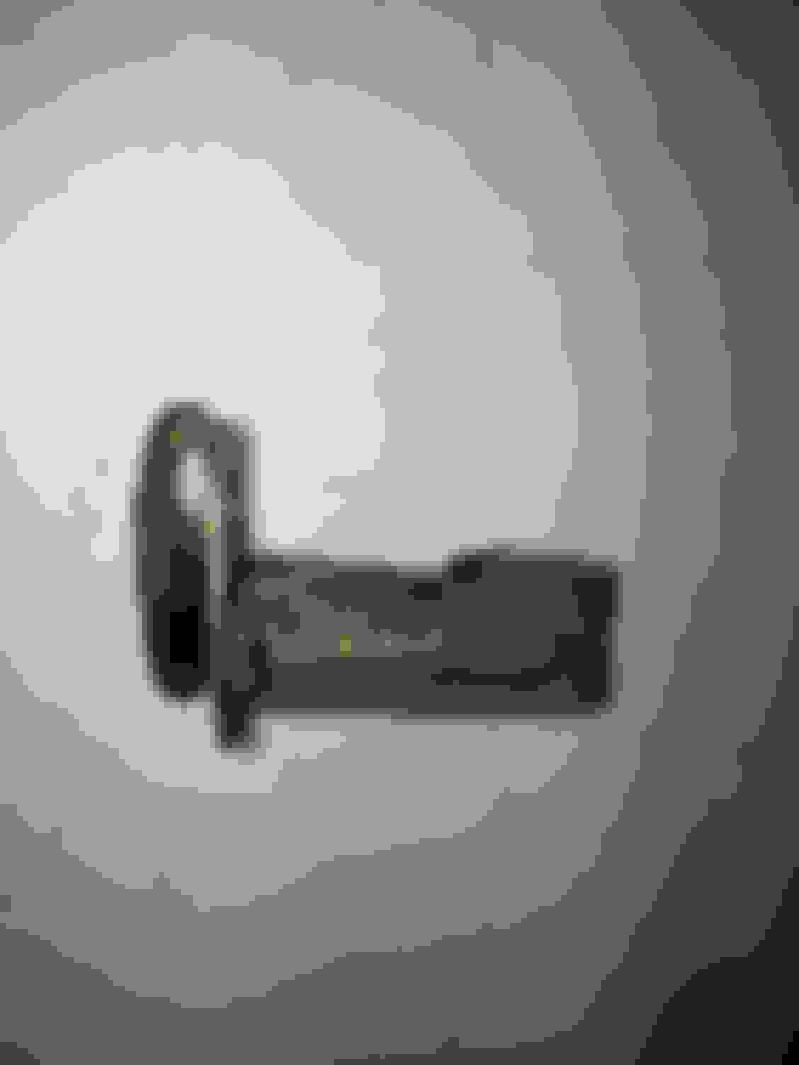
At the same time and skipping ahead a bit I also sanded and painted the the loose metal tie-down mount for the GTE water bypass pipe on the turbo & water pump side of the engine. I had a spare one also so they both got painted. They were both in rough shape and I didn't want them to rust any time soon. They got the same VHT primer, VHT Black and VHT Satin Clear. Unfortunately it was easy to break some of this paint off when it came time to clamp it to the block but still... much better than before.
The bracket (and its spare part twin) were both finished better than this partial job. I just forgot to take a final picture.
Now, the ACTUAL lower oil pan installation
First I installed the oil strainer/pickup gasket. The original studs were still on my oil pan. The nuts I used probably came from the Driftmotion oil pan bolt kit. I am pretty sure.
The oil baffle plate goes on next. You will find there is only one way it can go on to correctly line up all the bolts.
Install all of the bolts EXCEPT the one where the oil strainer bracket goes. That is done last.
The baffle plate bolts are all 78 inch-lbs (including the one that covers the oil strainer bracket that goes over the baffle plate). The two oil strainer/pickup nuts that go to the gasket area are 20 inch-lbs.
The Supra TSRM "LUBRICATION SYSTEM" EG-374 and EG-375 cover this.
Next, the lower oil pan is given a pattern of FIPG gasket maker in the diagram shown in the Supra TSRM "LUBRICATION SYSTEM" EG-375.
The sixteen bolts that tighten it down to the upper oil pan all get 78 inch-lbs of torque.
In my case I found that a couple of them didn't want to cooperate and fully torque down. They went so far but kept spinning. This concerned me. I have labeled those uncooperative bolts/threads with blue painter's tape in the pictures below. Gerrb assured me that with the FIPG in place and the rest of them torqued down there will be adequate seal to keep in the oil under pressure. I hope so.
Water pump 2JZGTE coolant bypass pipe
This was very easy. The 2JZGTE water pump gets a rear facing gasket. The coolant bypass pipe goes on. It uses two nuts (P/N 90080-17242). I forgot to note the torque for those, sorry. Then the pipe is held in place by a bolt on the intake side of the engine block's rear and an identical nut on the turbo/exhaust side using that little bracket that I cleaned up earlier (x2 bolts P/N 90105-08250).
Flipping the engine 180 degrees
I don't know about you all but I'm not a heavily built guy. For this I found I did need some help by having someone at the front of this long engine helping give some leverage at the front. Even with only this much bolted on and try as I might I was not able to turn the GTE short block by myself. Maybe it won't be an issue for some of you but I would argue that it can't hurt to ask for a little help anyway and save your back some unnecessary strain. Pulling a muscle or messing up your back for something like this isn't necessary or worth it. Unless you're exceptionally strong, my advice is to ask for some help if you think you need it.
With the bottom end buttoned up and the engine turned, it's now starting to look a bit more like a 2JZ
With the coolant bypass pipe installed it was now possible to get the GTE oil cooler onto the engine. I bought mine used a good four years ago from an SF member. I have heard you have to make sure these are in good condition with no coked up oil but this one had... if I recall... maybe only 26k miles of use. It also came with very new looking coolant bypass hoses and clamps so those were reused.
What I have changed from stock in this case is the large bolt that holds it onto the engine block called the "UNION". Whereas the stock 2JZGTE came with a plain union bolt I bought an IS300 2JZ-GE (P/N 90401-19008) which has a BPST (sp?) tap for the fitting of an oil pressure sensor.
This is a feature that I would like, however I have read from some SupraForums members that the oil pressure in this area after a GTE oil cooler can differ a bit from the oil pressure you'd get from a more common 2JZ-GE non-water-cooled oil filter housing setup.
I really don't know and I lack any firsthand experience to say one way or the other but my intention will still be to keep in this union bolt with the central tap and run an electric oil pressure sensor to one of my own gauges in the car's cabin.
There are some gaskets required to put this onto the block. The rubber O-ring was again lubed up with Lucas semi-synthetic engine assembly lube before being inserted. Then a couple of metal gaskets go into specific spots.
When assembled together the large Union bolt requires 65 lb-ft of torque (I believe this is correct). In the Supra MKIV TSRM EG-376 under "LUBRICATION SYSTEM" the exploded diagram of the GTE oil cooler is shown. Now I know I looked up the torque spec in the TSRM but I think that 65 ft-lb figure for the union bolt might have been in another section.
Next, as soon as I finish and gather all my pictures... cylinder head and camshaft installation. Probably the part that makes me the most nervous of all but it's all research, TSRM, and strict procedure
Next, the lower oil pan is given a pattern of FIPG gasket maker in the diagram shown in the Supra TSRM "LUBRICATION SYSTEM" EG-375.
The sixteen bolts that tighten it down to the upper oil pan all get 78 inch-lbs of torque.
In my case I found that a couple of them didn't want to cooperate and fully torque down. They went so far but kept spinning. This concerned me. I have labeled those uncooperative bolts/threads with blue painter's tape in the pictures below. Gerrb assured me that with the FIPG in place and the rest of them torqued down there will be adequate seal to keep in the oil under pressure. I hope so.
This sounds to me like the screws have stripped. While you're probably right that the pan will still seal, I would not personally be comfortable leaving it like that. I'm just pointing that out because you're putting in unbelievable attention to detail on everything else. You should be able to Helicoil the holes without pulling the pan apart.
This sounds to me like the screws have stripped. While you're probably right that the pan will still seal, I would not personally be comfortable leaving it like that. I'm just pointing that out because you're putting in unbelievable attention to detail on everything else. You should be able to Helicoil the holes without pulling the pan apart.
MLeopard, thank you for bringing this up This may be so and it was my concern at the time. I haven't left it like that for good but I had to keep on moving with the rest of the engine assembly since I have a finite amount of time right now to get everything together or at least 85% fully assembled and wired up.
As for those specific screws, you say I can "Helicoil" the thread holes? Is that the same thing as running a correct size thread tap?
I could order the OEM lower pan screws and remove each of the ones from Driftmotion but the threads in the aluminum pan in those areas might be the real issue. Well before assembly when I test fit the Driftmotion lower pan screws with the aluminum upper pan off the car they all went in (although I only started them a bit). This was when I discovered the slight bend in the lower pan which I had to bang back into shape.
Interestingly the affected screws only had trouble in the area where I had flattened out the previously bent area of the pan lip and in one other area on the other side... but it there was no deviation in the pan lip metal there.
When fixing the bent area of the lower pan I checked and re-checked that and did not use anything more than a soft rubber mallet to reshape it to what appeared to be almost exactly flat like the rest of the pan lip. I can't imagine there was enough deviation in shape left to overwhelm those threads at the specified torque in inch-lbs... which isn't very much.
Worst case I could replace the entire lower pan and use only Toyota OEM pan screws, assuming the upper aluminum pan threads taps aren't damaged in those spots. I could run a thread tap chaser if I knew exactly what size and pitch they are.
....
I don't want to leave it just like it is but my main priority right now is to get the entire engine built as much as possible within the time I have available-- at least to the point that mainly the wiring harness and turbocharger side are all that will remain.
Currently I am working through the entire intake side and I keep finding little things that I am missing that have to be ordered as I go.
And yes, those little things will all be noted soon along with the broader strokes. Currently there is a lot of catch up to post with a lot of pictures. Things will be posted here in the order that I assembled them. I will try to get the thread up to date shortly. Soon I will probably be posting at the same speed that I do more assembly.
As for those specific screws, you say I can "Helicoil" the thread holes? Is that the same thing as running a correct size thread tap?
A Heli-Coil is a threaded insert used to repair internal threads that have been stripped. You drill and tap the original hole oversize and install the Heli-Coil. The resulting repair is as good if not better than the original threads. I think the threads in your upper pan gave out for some reason and if you were to remove the screws the threads of the pan would probably come out with them. If that's the case, a factory size tap would do nothing because there's no metal there to tap.
Originally Posted by KahnBB6
I could order the OEM lower pan screws and remove each of the ones from Driftmotion but the threads in the aluminum pan in those areas might be the real issue. Well before assembly when I test fit the Driftmotion lower pan screws with the aluminum upper pan off the car they all went in (although I only started them a bit). This was when I discovered the slight bend in the lower pan which I had to bang back into shape.
Interestingly the affected screws only had trouble in the area where I had flattened out the previously bent area of the pan lip and in one other area on the other side... but it there was no deviation in the pan lip metal there.
When fixing the bent area of the lower pan I checked and re-checked that and did not use anything more than a soft rubber mallet to reshape it to what appeared to be almost exactly flat like the rest of the pan lip. I can't imagine there was enough deviation in shape left to overwhelm those threads at the specified torque in inch-lbs... which isn't very much.
Worst case I could replace the entire lower pan and use only Toyota OEM pan screws, assuming the upper aluminum pan threads taps aren't damaged in those spots. I could run a thread tap chaser if I knew exactly what size and pitch they are.
Before you chase this too much it's probably a good idea to make sure the screws you used are the correct size. Sometimes a screw the next size down will grab a little but not enough. I doubt your pan rail straightening had anything to do with this.
Originally Posted by KahnBB6
I don't want to leave it just like it is but my main priority right now is to get the entire engine built as much as possible within the time I have available-- at least to the point that mainly the wiring harness and turbocharger side are all that will remain.
Currently I am working through the entire intake side and I keep finding little things that I am missing that have to be ordered as I go.
And yes, those little things will all be noted soon along with the broader strokes. Currently there is a lot of catch up to post with a lot of pictures. Things will be posted here in the order that I assembled them. I will try to get the thread up to date shortly. Soon I will probably be posting at the same speed that I do more assembly.


 06-16-17, 10:42 PM