When you click on links to various merchants on this site and make a purchase, this can result in this site earning a commission. Affiliate programs and affiliations include, but are not limited to, the eBay Partner Network.
2JZGTE Throttle body Part 2 (well... an observation)
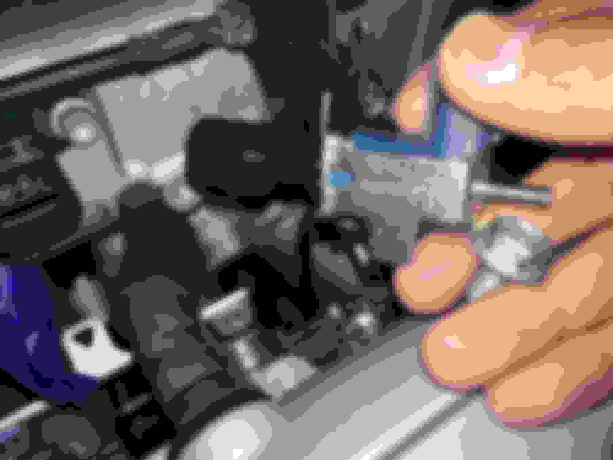
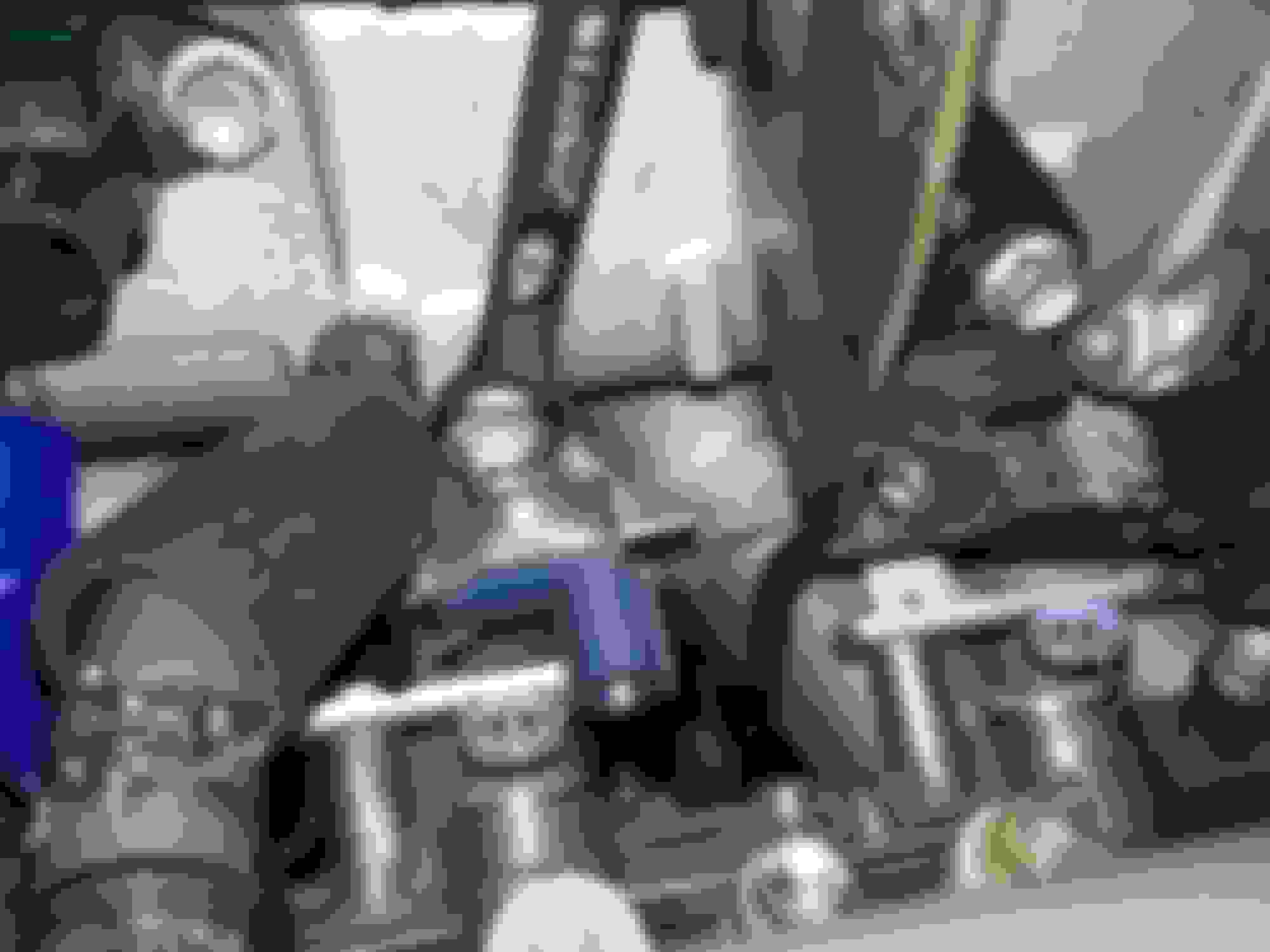
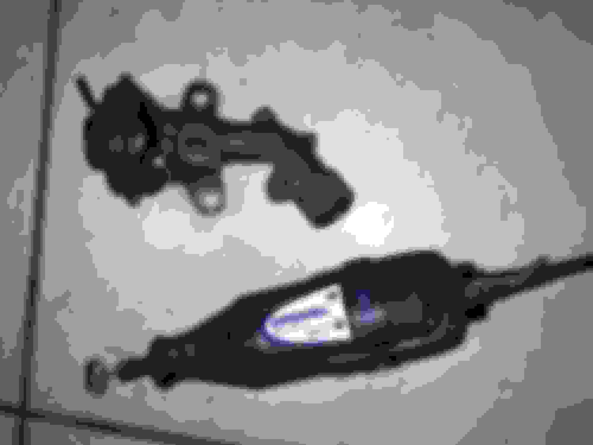
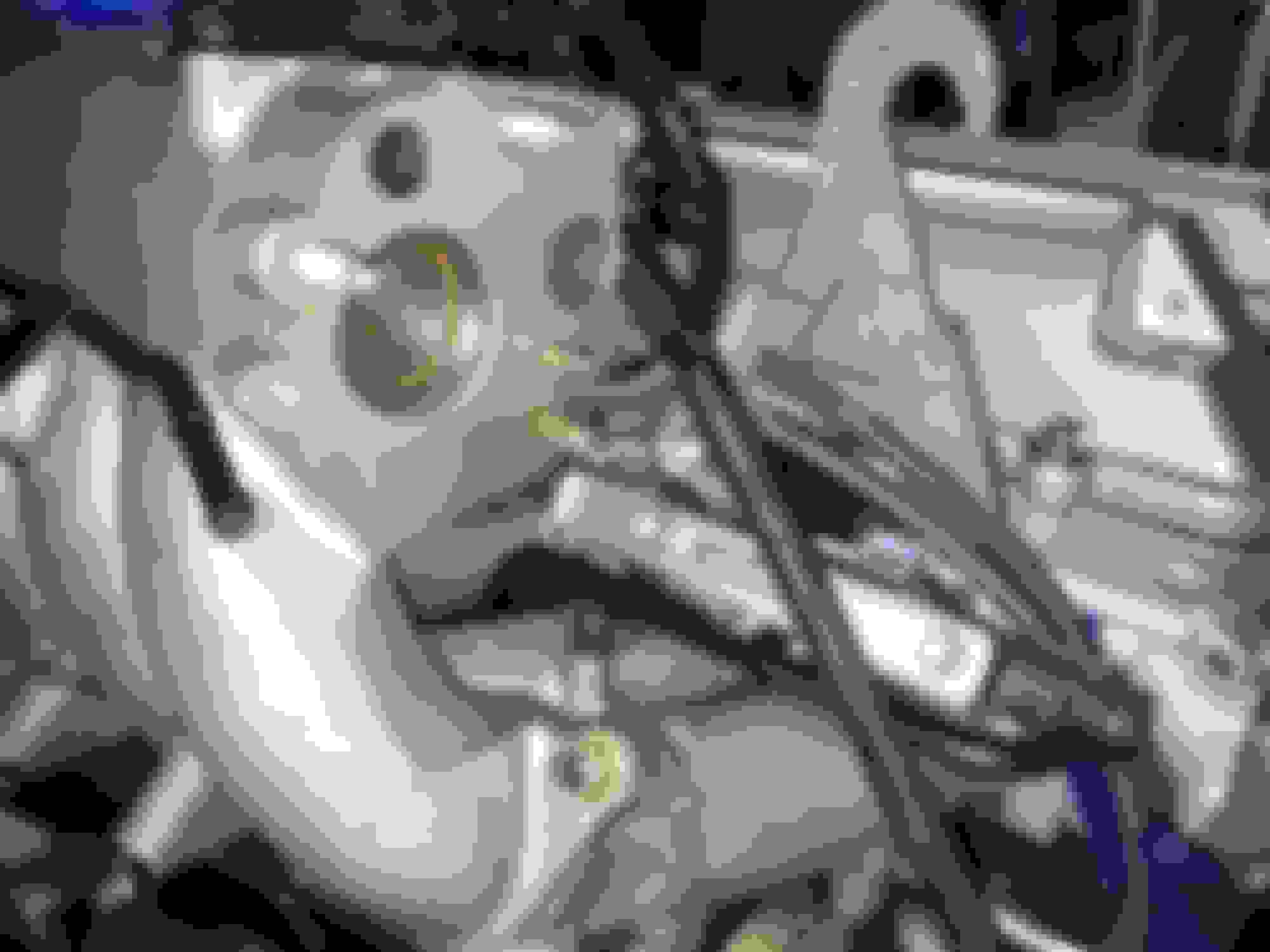
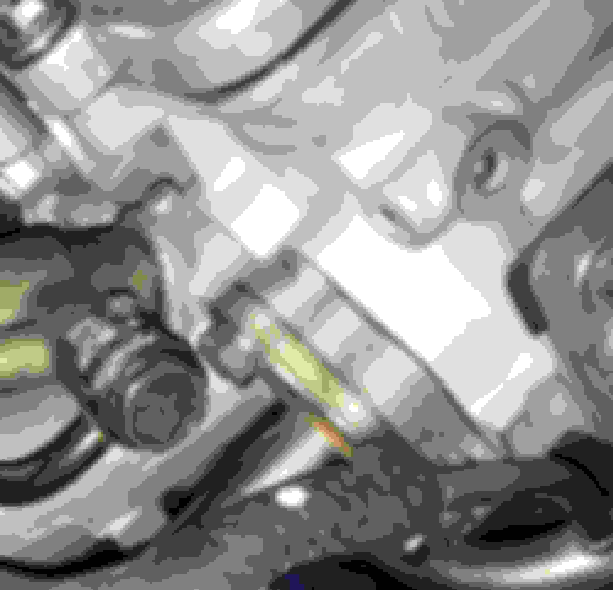
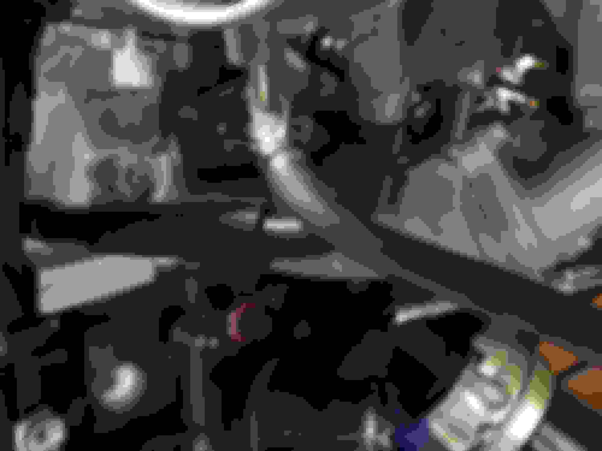
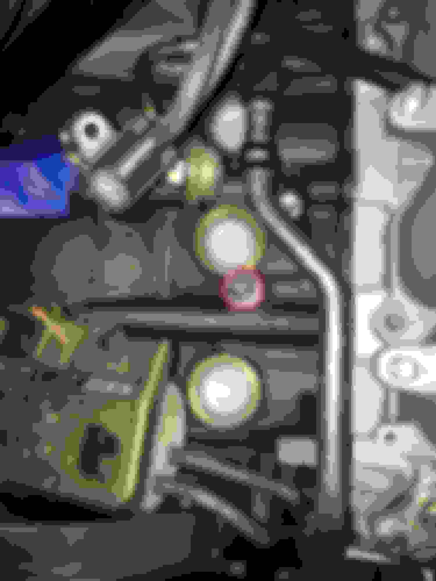
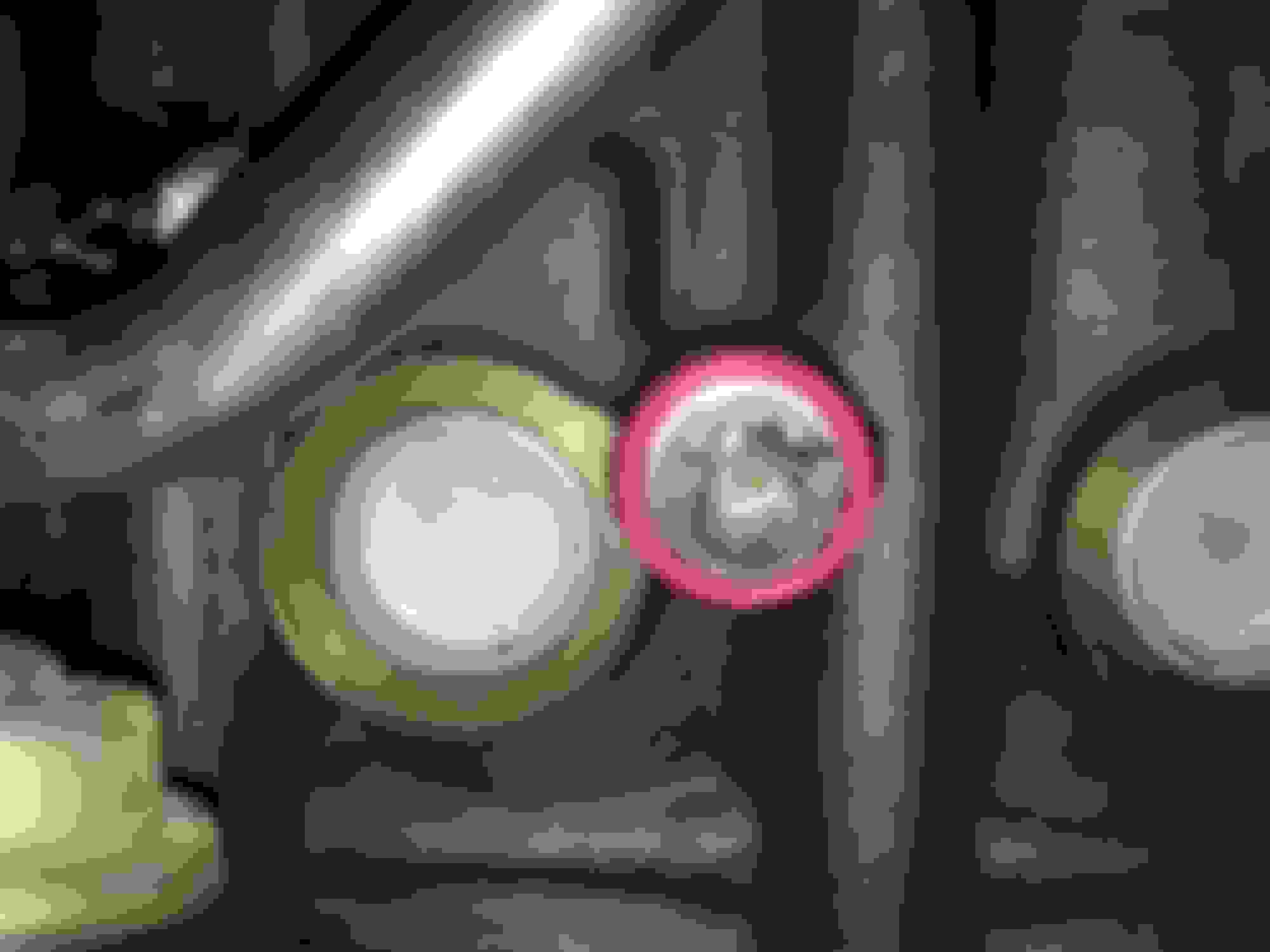
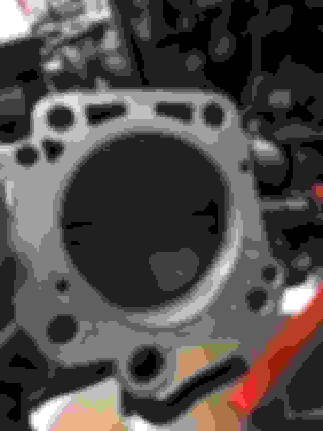
I noticed this when I began the TRAC delete installation. I bought the USDM 2JZGTE upper intake manifold and USDM throttle body a few years back. It never occurred to me that this lower connection which goes to a coolant(?) port on the cylinder head.... doesn't.... um.... have... anywhere to go on the intake manifold. It fully CONNECTS to something below the throttle body but the rear mating area of this port is a mystery to me unless it is supposed to remain exposed like this as a relief valve of some kind.
It has been a couple of months since I installed this and all the hoses I had for it so I can't recall if this lower bypass section is actually coolant or vacuum related. I assumed it was coolant related though.
Is it possible I got the wrong year USDM GTE intake upper or throttle body?
That is the coolant passage for the throttle body.
I'm not 100%, but I am pretty sure there should be a cap/plug in there basically like a small freeze plug. The coolant should not go into the intake manifold.. lol.
Basically the way the gte is setup is that the coolant bypass hose runs from the main block water pipe, though the IACV and throttle body, and then back to the pipe somewhere...
You can use it like that if you bypass the throttle body, but if you are shooting for all stock like I think you are, you want the freeze plug and appropriate coolant lines to the IACV etc..
Ali, thank you. I looked up my parts notes again and indeed as you said it is a coolant pass through. What's weird to me is why anyone would bother to remove a small freeze plug from that area? I don't understand what it would accomplish to do so.
The coolant lines I have (although one from the throttle body itself was discontinued so I had to improvise with another factory hose) and it is definitely going to be routed 100% like factory so this has to function however it was designed to originally.
I haven't come to the point in the photograph posts to show it yet but most of this IACV coolant routing up through the throttle body has been connected at this point (you'll see in a few posts). It's this one rear facing area of the GTE throttle body that made me scratch my head. Now I know why :/
These pictures will be just a bit out of order because at first I ordered an incorrect ECU coolant temp sensor. Twice
Apparently I was looking at the wrong diagram for that one.
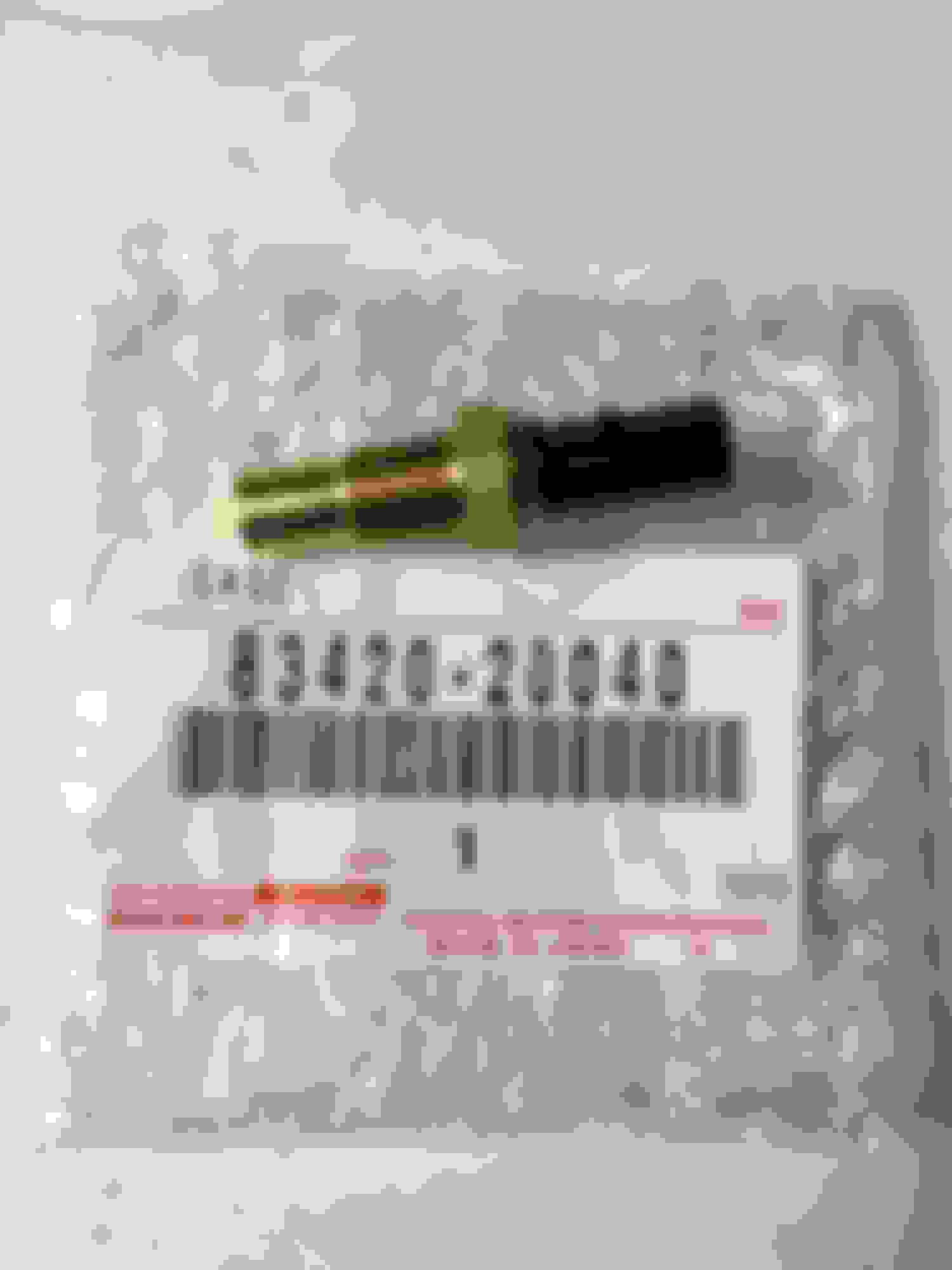
First I got the sensor for the cluster temperature gauge. This one is specific for USDM MKIV TT's. It should be a slightly different one for JDM 2JZGTE's. Further, vigman pointed out in his own thread a while back that the USDM 2JZGTE coolant temperature gauge sensor is calibrated for the MKIV engine temperature cluster gauge whereas our SC engine temperature cluster gauges require different values to read accurately.
Gerry (Gerrb) has told me that JDM 2JZGTE coolant temp sensors for the cluster gauge don't seem to throw off our SC cluster gauges... so this is probably a situation unique to this particular gauge sensor.
Also further, in a post some time ago from Phil Auldridge (who wrote and sells a USDM 2JZGTE swap manual/guide for SC300's), it's suggested that a 330 ohm resistor in line at the gauge itself or after the sensor connector wiring worked for him to get his 83420-20040 sensor's signal adjusted for values that the SC300 engine temp gauge reads accurately.
I'll try the 330 ohm resistor trick later when the engine goes in and I'll also need to jumper two connections on my cluster (R180?) for my tachometer to read correctly.
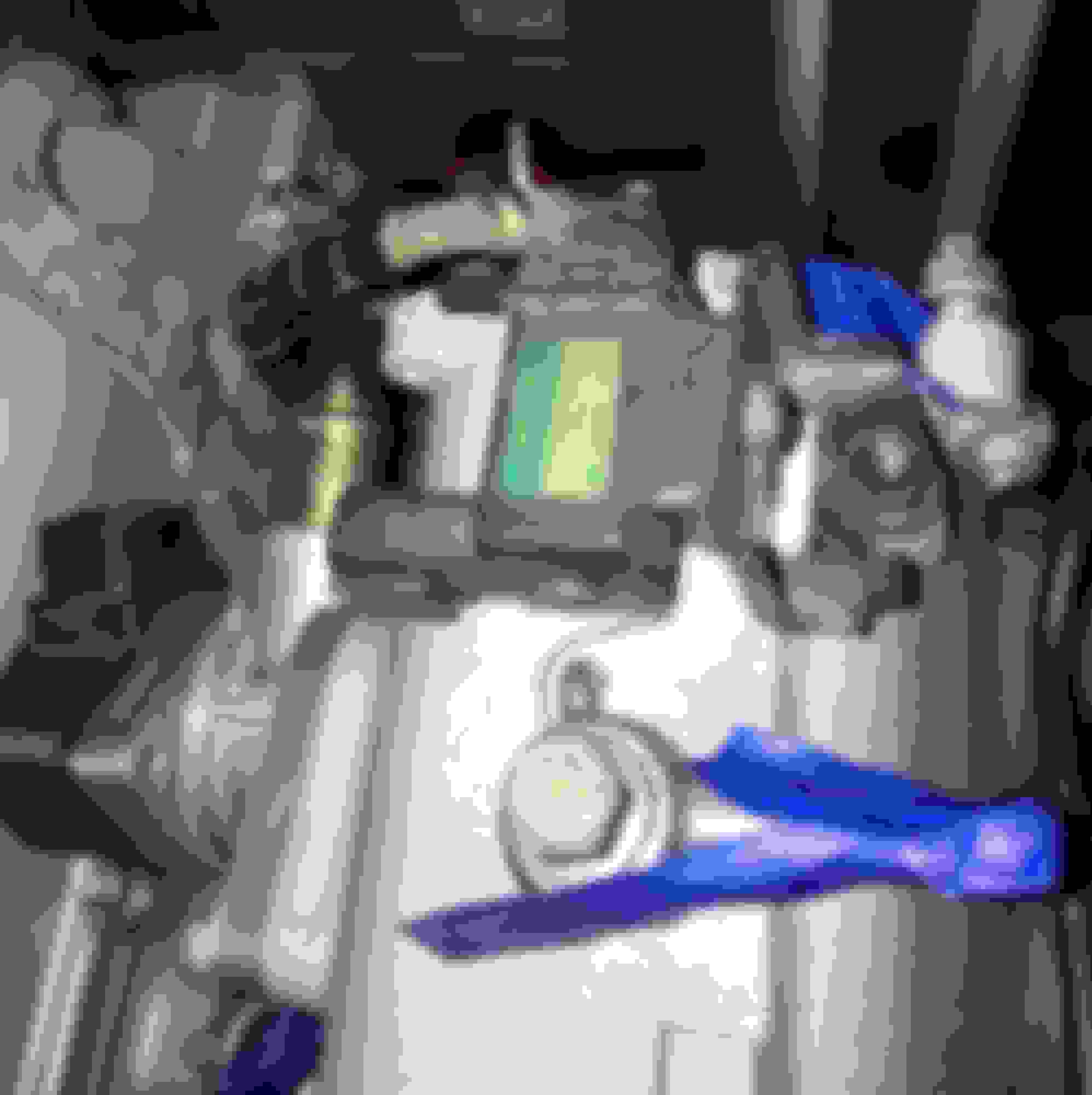
The USDM 2JZGTE 1-pin gauge coolant temp sensor for the upper water bypass neck is: 83420-20040. Use 11 ft-lbs of torque.
The USDM 2JZGTE 2-pin ECU coolant temp sensor for the upper water bypass neck is: 89422-35010. Use 18 ft-lbs of torque.
And the ECU coolant temp sensor also uses a gasket: 90430-12022
(The 1-pin coolant gauge sensor does not use any factory gasket)
I used a little Permatex thread sealer on both sensor threads.
This goes onto a certain spot on the inside galley between the intake manifold and the intake side of the cylinder head. It uses a common bolt with a 10mm end to fit in place.
Nothing special to install all of these. It's mostly just finding them all since they're discontinued. Except for the gaskets. You can still get those.
NOTE: In these pictures I temporarily removed the small steel 90-degree tube that goes onto the EGR valve in order to clean inside the cast port area of the main housing and clean out the inside of the steel tube. I once had to do this to my 2JZ-GE's EGR valve to clear it of carbon blockage so I figured this was a good time to run some carb and choke cleaner and small cleaning tools in this used EGR valve. I replaced the little 90-degree elbow before installing the EGR valve onto the intake manifold.
The TT EGR VSV (17630-46060) goes on top of the TT intake manifold. It uses a small common bolt. I just took one from a jar of spares I had. The hose on this one came with it so I left it on there for now.
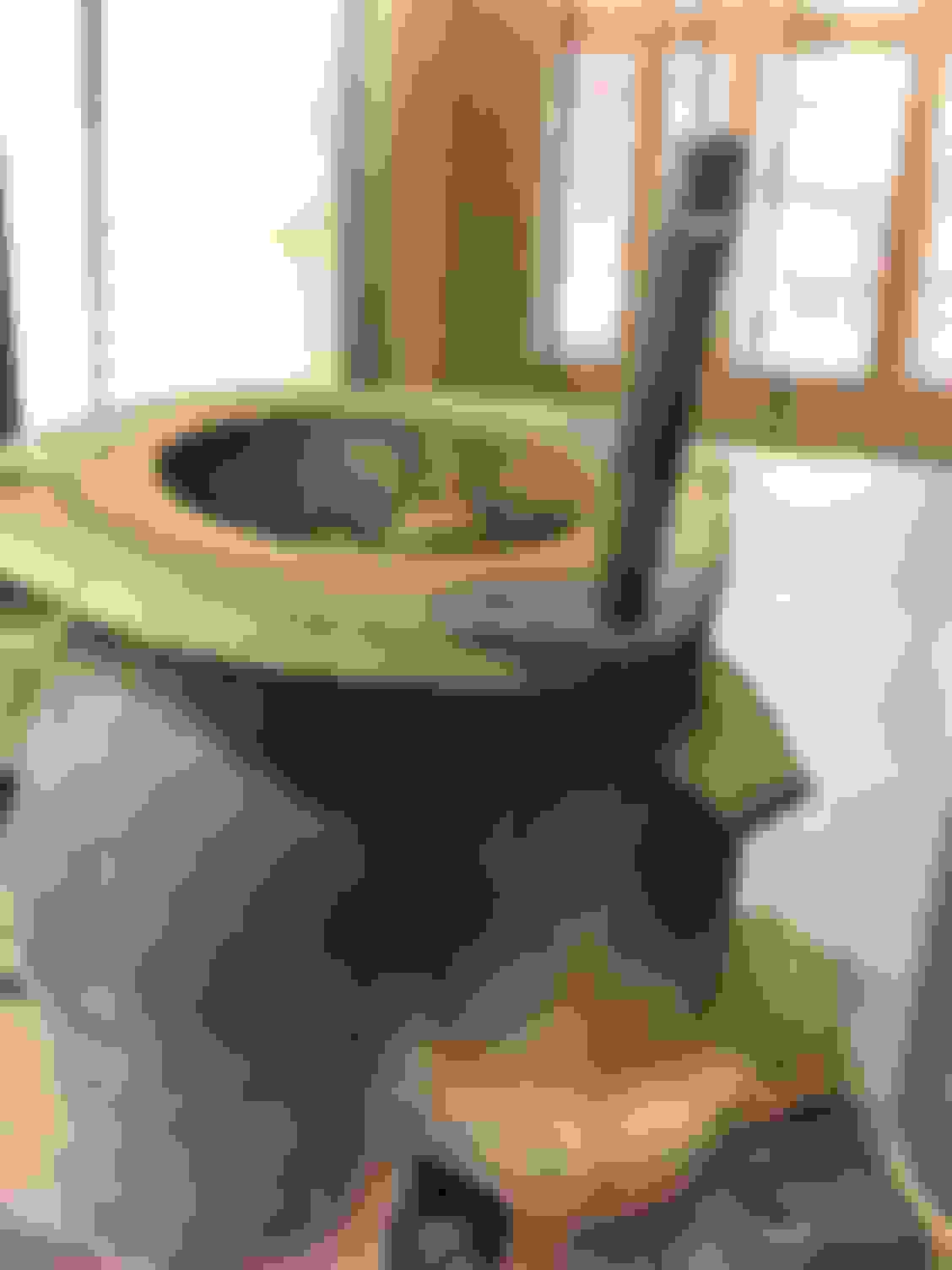
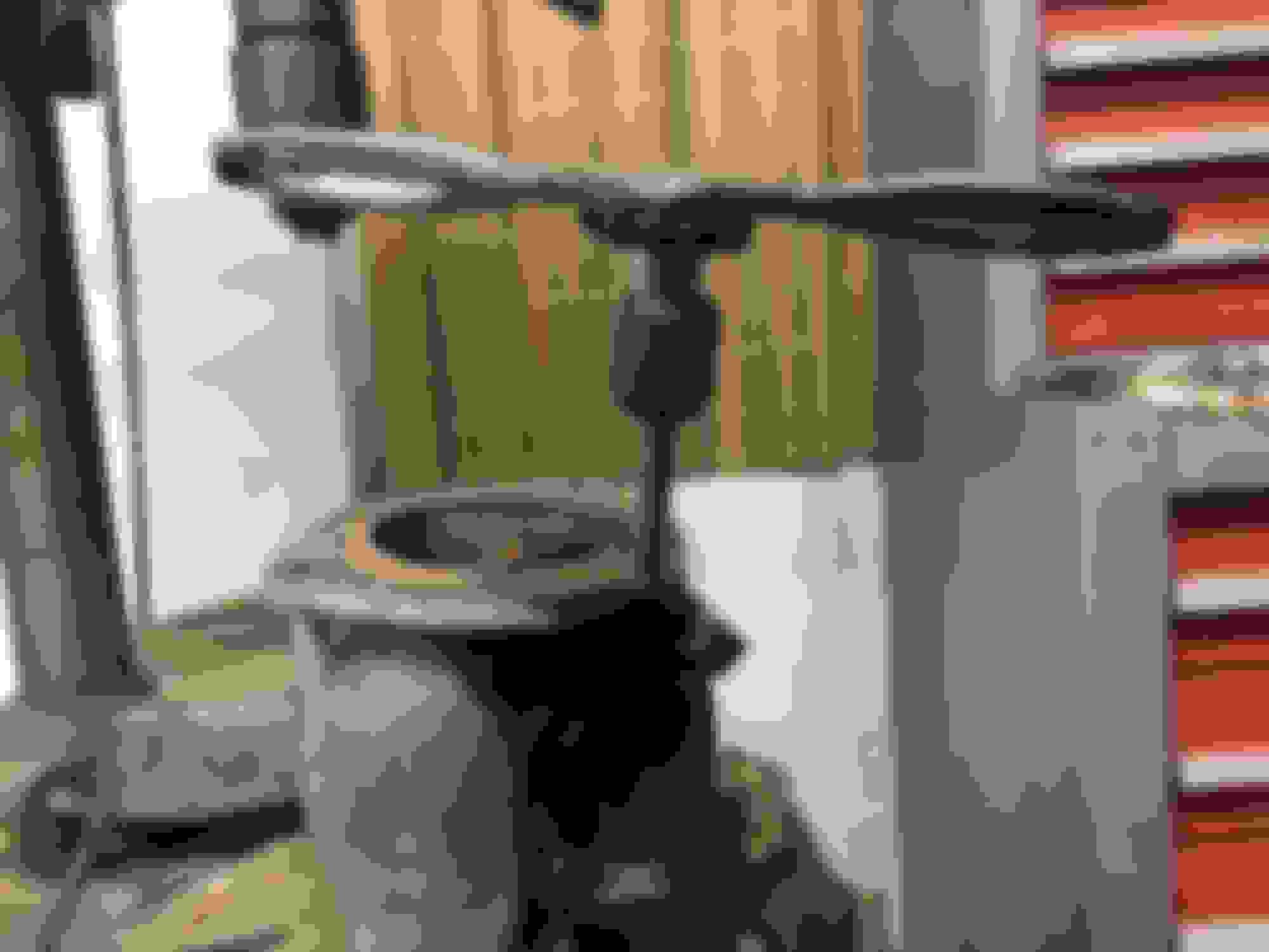
Then I wanted to clean up the surface rust on my TT EGR valve before installing it. I used a light metal wire brush on a Dremel. Normally I'd use a multi-speed Dremel but this single-speed model is all I had at the time.
I also used a wire "toothbrush" for some cleaning. What I was not going to do, since parts like these are so rare and difficult to substitute, is use any type of acid type rust removing liquid or compound. If there's a foolproof way to do it I just wasn't aware but there is no way I'm chancing anything that isn't going to fully preserve the cast steel right down to the threads for the pipe nut.
At the rear of the USDM intake manifold two studs for the EGR mounting are installed.
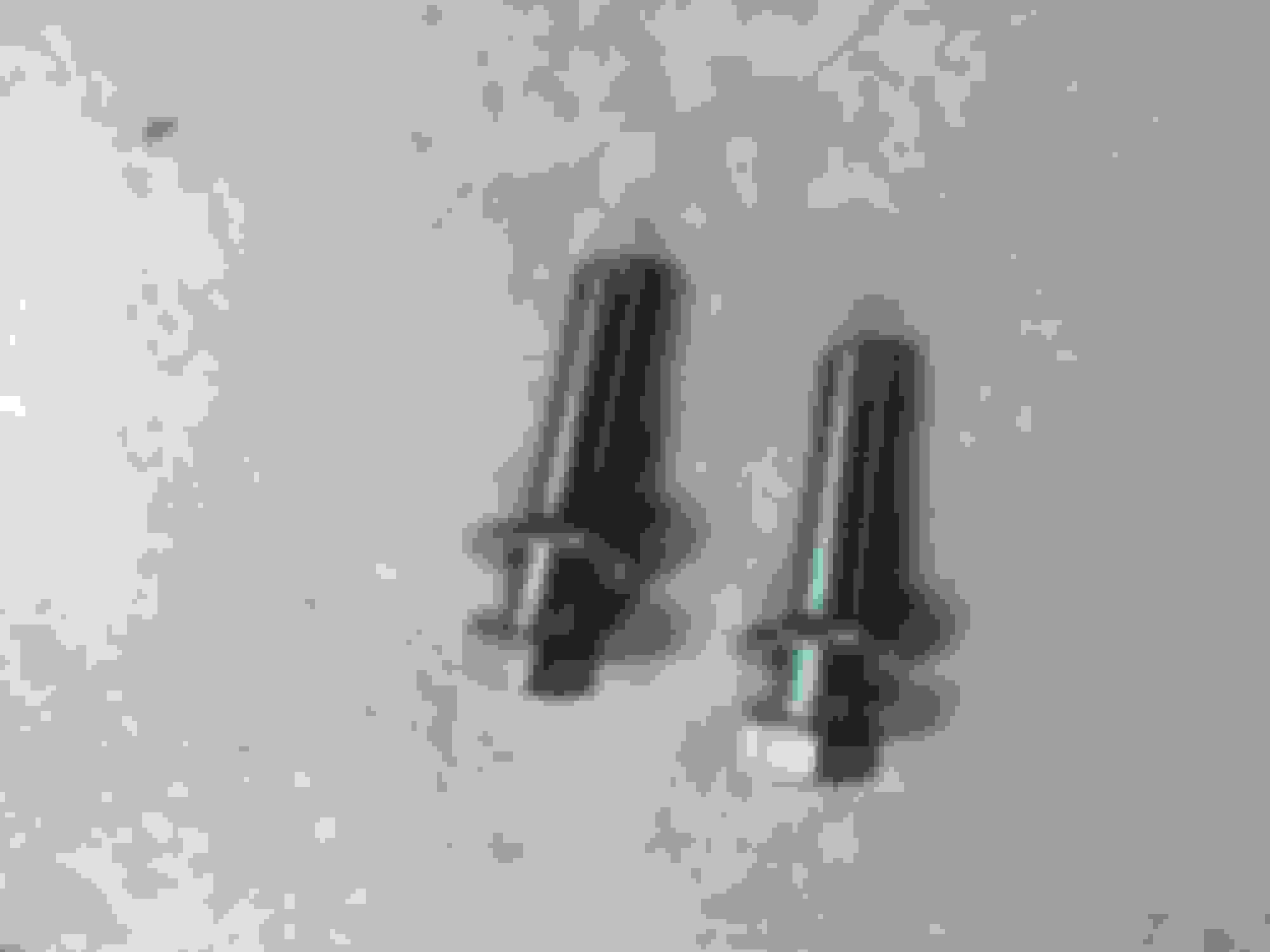
A problem arose when I went to order the studs that go into the USDM 2JZGTE cylinder head to allow the metal EGR pipe to be torqued in place.
Toyota discontinued them. Amazingly helpful there, Toyota. Slow clap.
I thought of using another spare stud I had from installing the intake manifold to the cylinder head but as I had thought, these studs were the same thing but just a bit longer to allow for the extra thickness required.
So I went to a local hardware store with one of those spare intake manifold studs and began hunting through their metric bolt section.
I came up with some M8-1.25 screws and some 8mm washers. I knew the torque might come out differently if the pull was coming from the bolt head and threads (my solution) versus just a nut onto stationary threads (Toyota's discontinued factory solution) but as long as I stuck to the torque values they wanted I didn't think there would be too much variation.
The store bought M8-1.25 bolts compared to a factory 2JZ intake manifold bolt which was also too short to use for the EGR pipe connection.
TT IAC-V rear water bypass hose & Combination IAC-V front water bypass hose + EVAP VSV Vac hose
First, a rear bypass hose for the TT IAC-V (16281-46020) goes onto the rear-most IAC-V bent pipe under the curve of the intake manifold with two (2) clamps (96135-51300).
Then combination hose 16267-46011 goes onto the front-most IAC-V connection under the intake manifold's curve and connects to a small steel "manifold stay" combination pipe with two (2) clamps (96135-51300).
At the time the first photos were taken I did not have this additional "manifold stay" combo pipe. Of course, Toyota had discontinued it so I had to seek one out used. Thanks again, Toyota.
For now I left that front IAC-V coolant bypass connection undone.
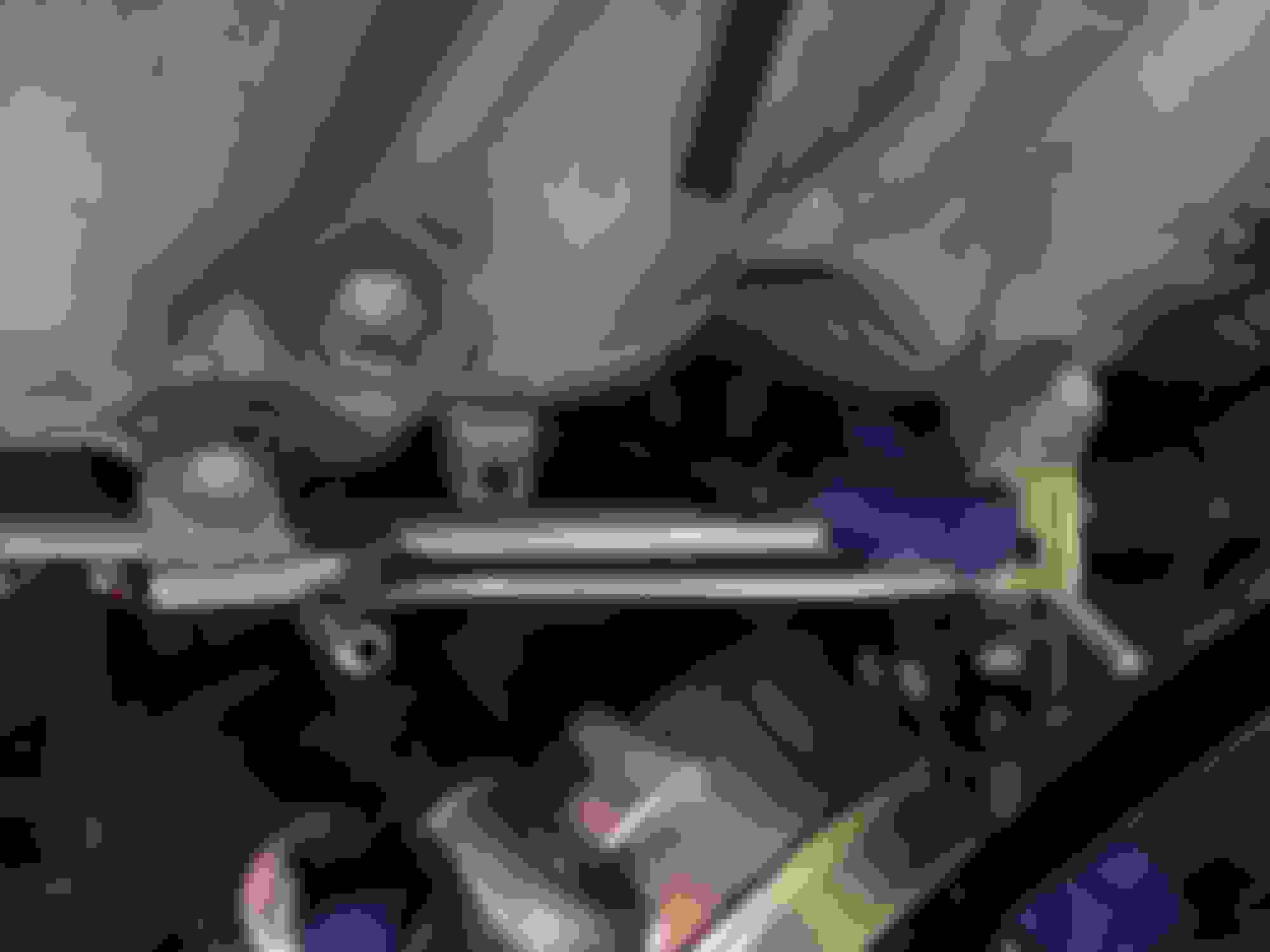
The vacuum hose is for another purpose. That connects to a vacuum source from the intake manifold plenum and routes to one of the two steel vacuum tubes built into the BIG "intake manifold stay" that was installed earlier. This is for the EVAP VSV connection. Later this is routed closer to the front of the intake manifold into a splitter pipe that uses a check valve.
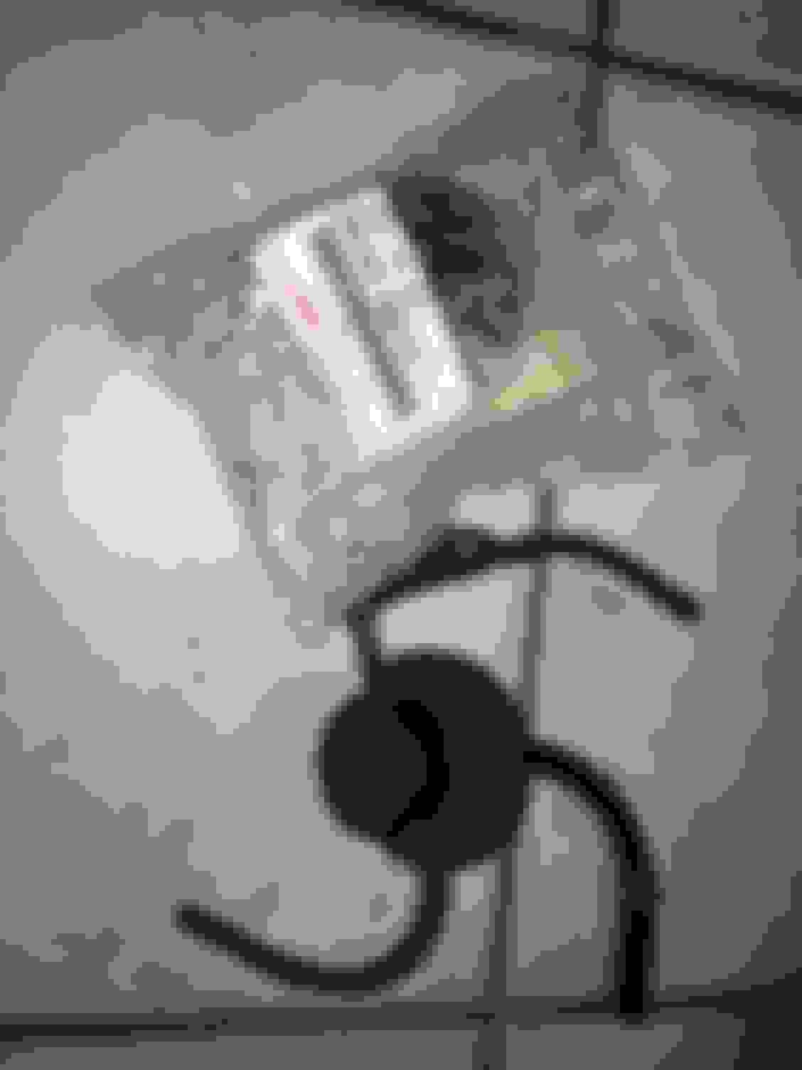
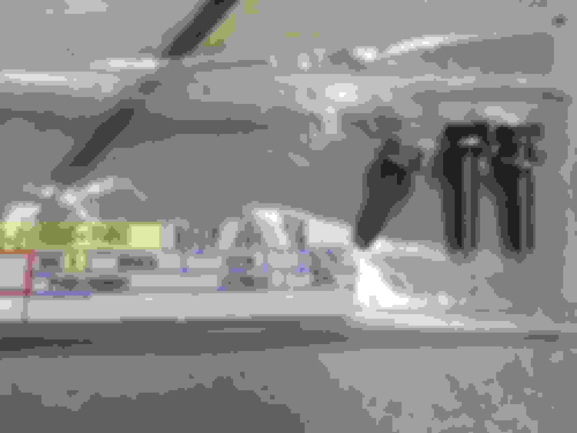
Later, however, I did find a used small "manifold stay" for this section:
That pipe needs two bolts: 91653-A0614
You can see in the far right of the image above that the 16267-46011 hose coming from the IAC-V is connected to this factory dual pipe.
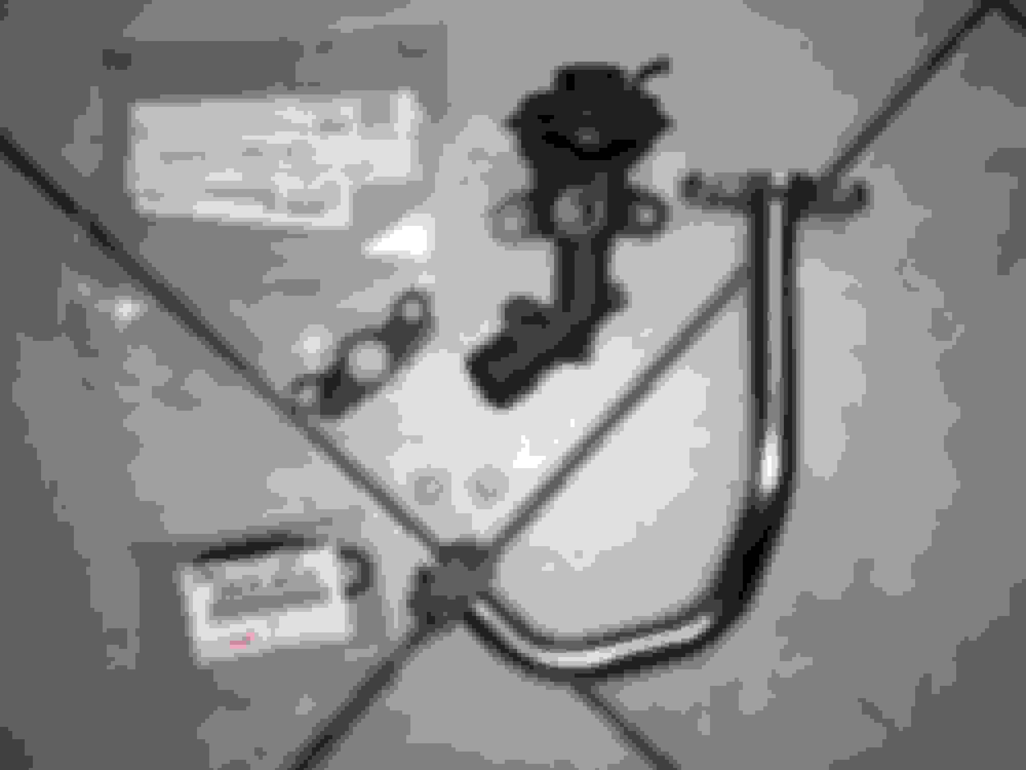
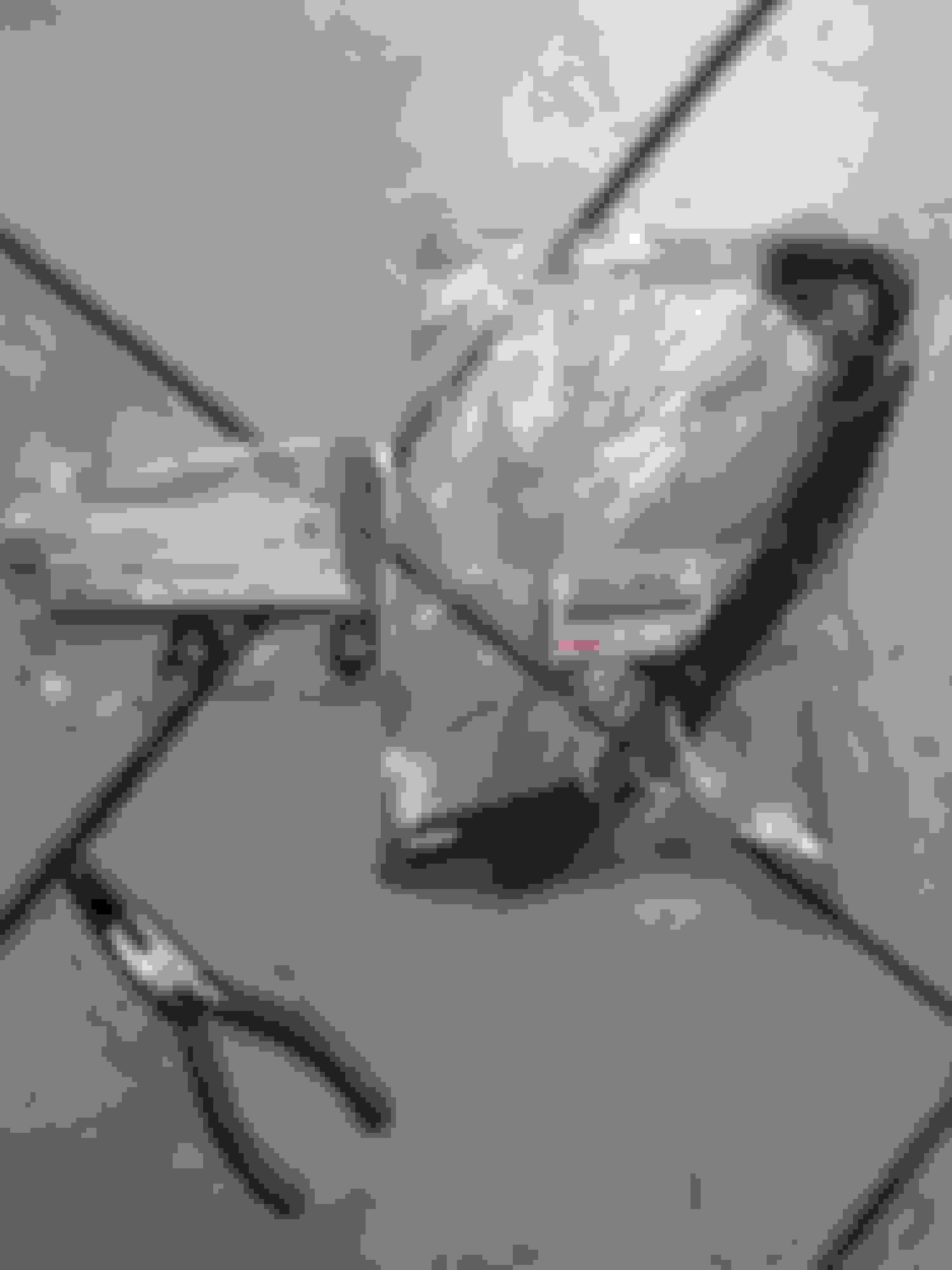
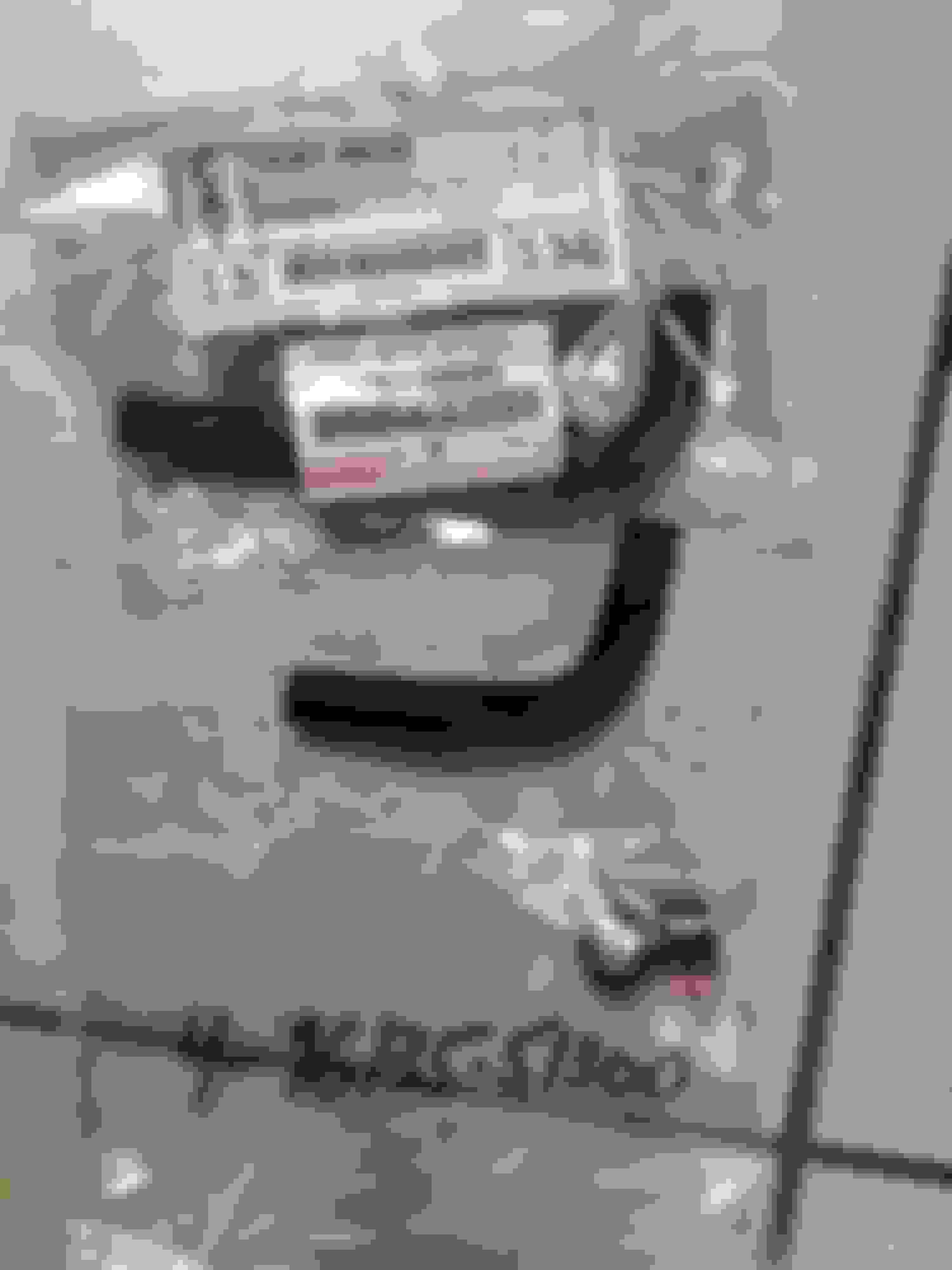
Jumping ahead, another hose goes from the GTE throtle body to a coolant port on the cylinder head... but Toyota discontinued this (of course)... so I used a substitute hose (16261-46050) and two (2) clamps (96135-51300) which feels just long enough without being too short or too long. I can't remember how I found this hose but for some reason I had it in my parts pile at the time.and it wasn't earmarked for anything else. The length of the hose doesn't leave any extra give but I can't see it moving around either.
The old hose compared to it in the picture came off the throttle body. That was cut short when the previous owner removed it from the original car.
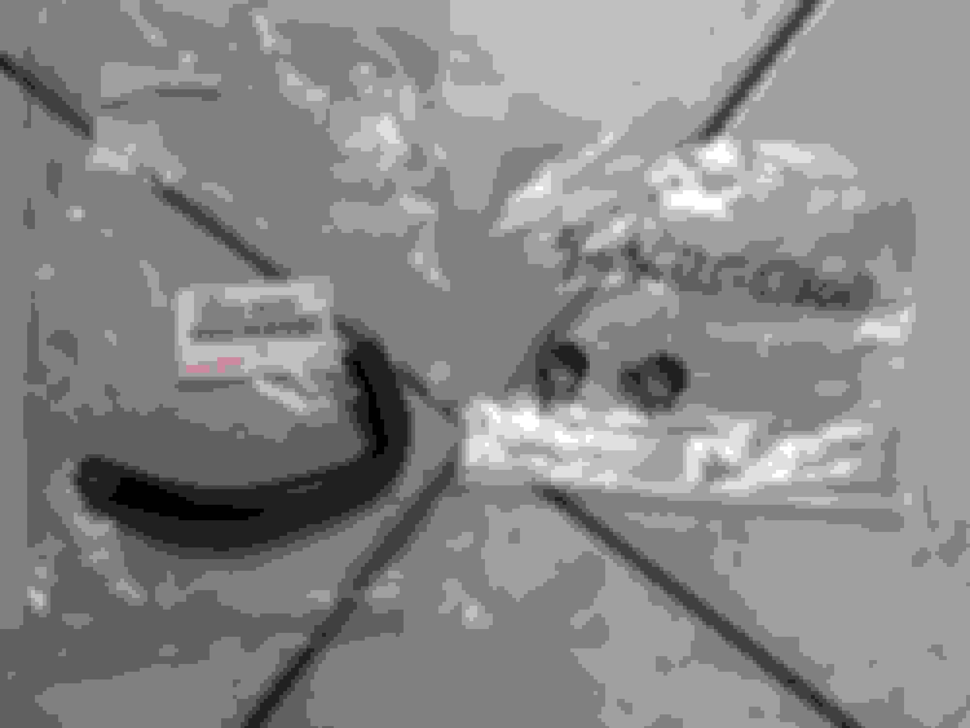
Jumping back, now, I picked up hose 16264-46030 and two (2) clamps (96135-51300) to connect the "stay" bypass pipe coolant connection to the GTE throttle body.
At this point the only lingering question is whether or not the rear lower port on the throttle body actually needs a tiny freeze plug or not.
Last edited by KahnBB6; 09-30-17 at 06:33 PM.
Reason: updated with bypass pipe pictures
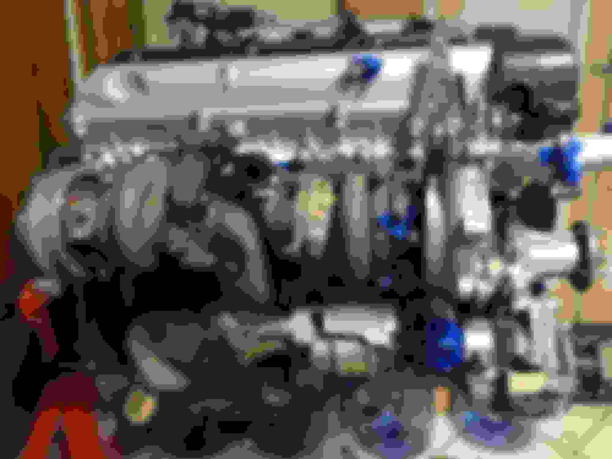
Test fitting the sequential twin turbo main assembly
This was necessary to do just to get a sense of where things bolted up, where the exhaust side engine mount bracket needed to be and also to provide leverage to remove a pesky seized lower exhaust bolt. As I was soon to find out, these bolts seizing and snapping off in the housings are not an uncommon occurrence with 2JZGTE stock twins that have a lot of age on them.
The turbos pictured are the ones I ended up using. I bought them in 2013 with 150,000 miles on them so claimed the previous owner, whom I met. I did get to see the MKIV TT they came out of and he seemed like a fellow who really took care of his car. However he did tell me they had been run at 18 PSI max before he removed them. He claimed no oil seal smoke or issues with them. From him I got a complete USDM twin system and most of the sequential side parts you're seeing me recondition for this build.
Currently I haven't left myself any budget to rebuild these twin turbos so for now I am betting they still have some good life left in them at stock boost. These have no had oil in their shafts for at least 4-5 years but the turbos spin freely with very little side to side shaft play and zero in-out shaft play. The blade alignment in the housing appears to be good and the blades themselves aren't nicked on their edges.
On the other hand Gerrb happened to have a set of 40k mile USDM twins with very little shaft play (and no in-out) for sale back in late July and being the cautionary worst case scenario planner I am I bought them from him too. Thank you Gerry!!
For the moment though I am going with these 150k mile twins. And it is my intention to be able to still rebuild them later on so I don't want to run them into the ground beyond the point which they would be non-rebuildable.
2021 Note: It turned out that while the #1 CT12B turbo was in good working condition the #2 turbo shown here was already bad as I would learn much later on after having broken in the engine. If I could go back to myself in late 2017 at this point in time I would halt the project until both turbos could be professionally rebuilt before continuing the engine assembly. As most of you probably know it is VERY involved and difficult to remove and reinstall the stock turbochargers with the engine in the car (though it is all doable it is a very demanding job) and when going to all of this trouble to keep the fresh engine stock and NOT change to a single turbo later on but rather keep the stock twins it is a no-brainer to just get your used CT12B's rebuilt so that there will be no issues from pre-existing wear and tear on them.
I wish I had done that during this stage of the build but at the time I was trying to save money (about $1500 or so when rebuilding both stock turbos) and having had no prior ownership experience with a turbocharged car I naively felt confident that it would be okay to throw on the used 150k mile set... which I bought from a Supra owner who had just switched over to a single turbo in his car.
In hindsight, and with self-directed sarcasm, I wonder just what motivated him to have removed his stock twins and swapped over to a big single turbo after running his stock twins at BPU with the #2 boosting up to the "safe" 18psi limit? Could it be that at some point his #2 turbo went out? It took me a while to realize it after after my swap was up and running because at the time I lacked experience with the telltale sign of a 2nd turbo failure on a sequential twin turbo system but that indeed turned out to be the case.
For a long while after my swap was running I kept assuming that my clutch was slipping and therefore must have been inadequate for the engine's torque by 4,000 RPM. No... it was just the worn out #2 CT12B turbo whining loudly and creating a wall of back-pressure every time the sequential transition system tried to get it spooling.
It would have been no issue if I had just sent both turbochargers out for rebuilding before assembling the whole system on the engine.
Learn from my mistake. It you're building a 100% stock engine setup like this one which you intend to keep stock including the factory twin turbos, just get them rebuilt before installing them on the engine. If, as I did, you think you'll be saving money by throwing them on just because they seem to have "little" or no shaft play... don't. Just wait a little longer or do what you need to do to get them rebuilt and fresh again before proceeding with your engine build.
Anyway at stock boost, depending on how you drive on them and how well you care for them (ie: allow for cool down periods before shutting off the engine and change the synthetic oil every 2,500-3,000 miles), they can last anywhere from 150k-300k+ miles... from "new"/rebuilt condition.
The exhaust manifold stud nuts were not torqued down for this test fitting. This was secured onto the cylinder head just enough to be stable for evaluation.
And here is the entire turbo system removed from the engine and almost completely dismantled. The turbos might not be getting rebuilt but new gaskets were going in across the board and some of these numerous studs were going to be restored to remove surface rust buildup. Some major parts were going to have rust removed and they would have high temp primer and paint applied.
Last edited by KahnBB6; 02-13-21 at 05:23 AM.
Reason: Added 2021 reflection
How to remove and replace a seized sequential twin lower exhaust stud that has broken off
This part was one of the most annoying and ridiculous chores on this build.
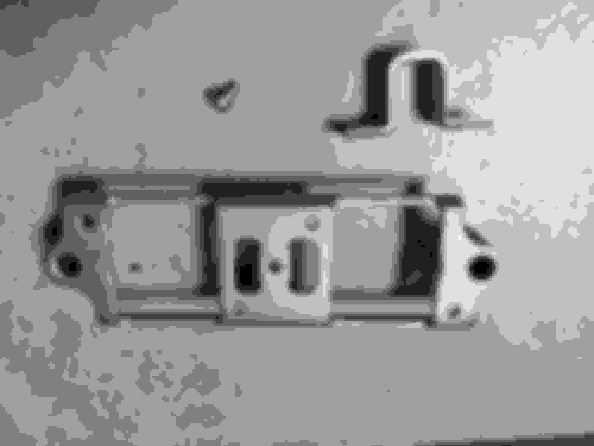
The lower exhaust manifold from the stock twins just before the #1 catalytic convertor has three but exhaust studs. Sometimes after much time... they snap off if you try to remove them.
I soaked this stud in PB Blaster and waited some time before attempting to pull it. No matter. This studs threads were rusted in place.
I was certain the Mayhew 360-degree stud puller tool would make this easy. Nope.
THAT is annoying. Now I had no choice but to drill it out or use a bolt extractor.
Long story short I was going to try some common Lowes or Home Depot bolt or screw head extractors but it was obvious I needed something very heavy duty to accomplish this job.
I bought an Irwin Hanson 10 piece extractor and matched drill bit set. These are all strong cobalt bits.
First I tried this with any of the biggest hand bit extractor/tap handles-holders I had in the workshop. None of them had the leverage I needed. I also tried a corded variable speed DeWalt drill which was not ultimately ideal for this.
The exhaust housing had to be C-clamped down to a wooden platform in two places just to stay secure enough to do anything at all.
Still nothing. And I had to use the biggest drill bit and extractor I dared get away with just to have a hope of gaining enough torque on this rust seizing.
Then I bought an Irwin Hanson big propeller handle set and ditched the smaller extractor/tap handle I was using. PB Blast was soaked into the affected area over and over. I had also been using some light application of thick engine assembly lube on the target area while doing this.
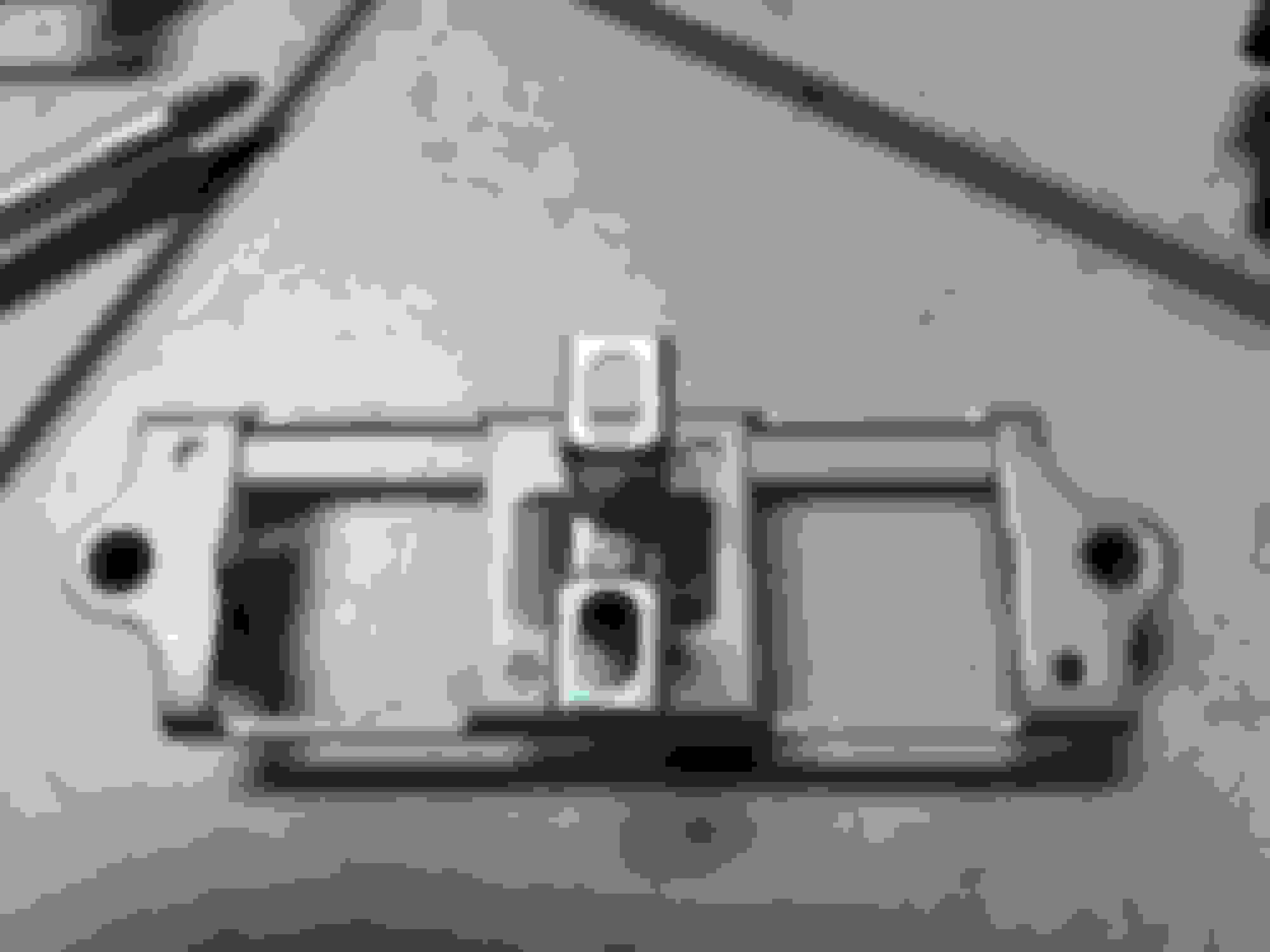
That did it. Finally. I hadn't managed to keep the drill bit perfectly centered to allow for the tap to be perfectly centered so I grazed one area of the threads in the iron housing but once I cleaned out the threaded hole with a wire brush and the new exhaust stud went in tight and secure once all of its threads cleared the surface of the housing.
This small little bracket has also been discontinued by Toyota. Another hunt in the classifieds and eventually I had one.
I don't have the pictures for it but I did take a wire brush to this to remove surface rust and I put this in Evap-O-Rust solution for a day before washing it off, coating all surfaces in primer and then in some 500F VHT FlameProof black and VHT 500F FlameProof Satin Clear.
My block came with a set of these and I have kept them but I didn't want to chance going to all this trouble only to find one of my knock sensors (basically two microphones the ECU uses to listen to your engine block for detonation, knocking, and pinging) had gone bad.
They are the same and you need two of them: 89615-22030
I did not use thread sealant for this installation because as you'll see the area of the block these go into is just a blank recessed area for the threads to sink into. They are there purely to listen to the sound that is being transmitted through the iron block of the 2JZ.
They both go in with 33 ft-lbs of torque. The one in the rear is located behind the TT pressure tank so you have to temporarily remove that to install it. A deep socket is needed to clear their connector ends.
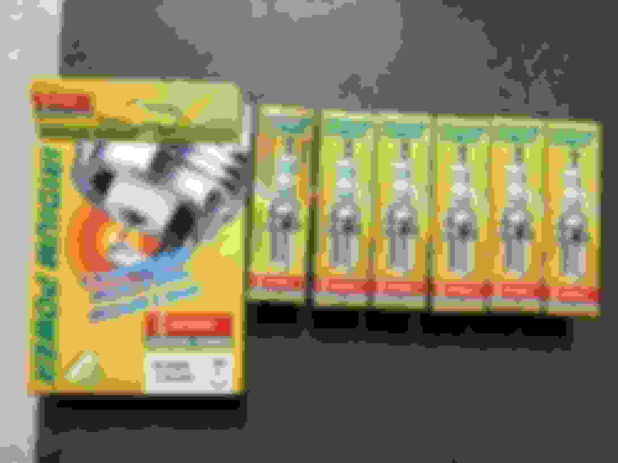
New spark plugs, TT coil pack holders and old used untested coil packs (for now)
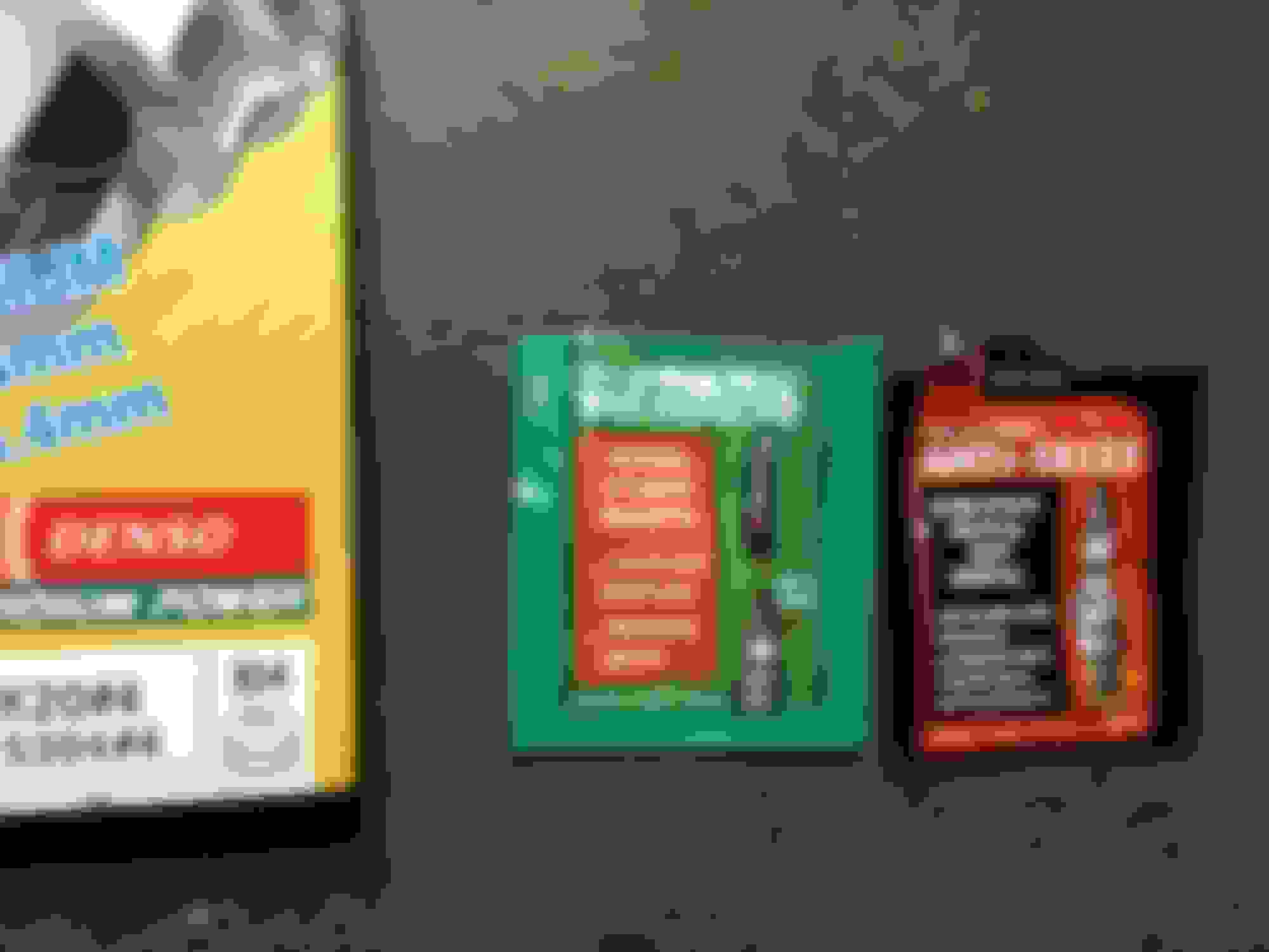
After a lot of reading I settled on using the Denso Iridium IK20 spark plugs for my stock boost application. If I go BPU down the road I will use different recommended plugs.
You don't want to forget packets of thread anti-seize and dielectric grease to protect the coil boots.
Same as with the 2JZ-GE, the plugs go in with 13 ft-lbs of torque.
The coil packs I had on hand were part of a throw-in deal with some other parts from a forum member. They didn't cost much and I haven't tested them to make sure they work but since they aren't hard to remove and install I decided to throw them in for now anyway. I will replace them later.
It turns out I had ordered one too few holder brackets but thankfully the used coil packs came with their own brackets so I just used one of those with the new ones.
Rear IAC-V Rear Crossback Pipe, Connection hoses/clamps and stabilizer bracket for the pipe
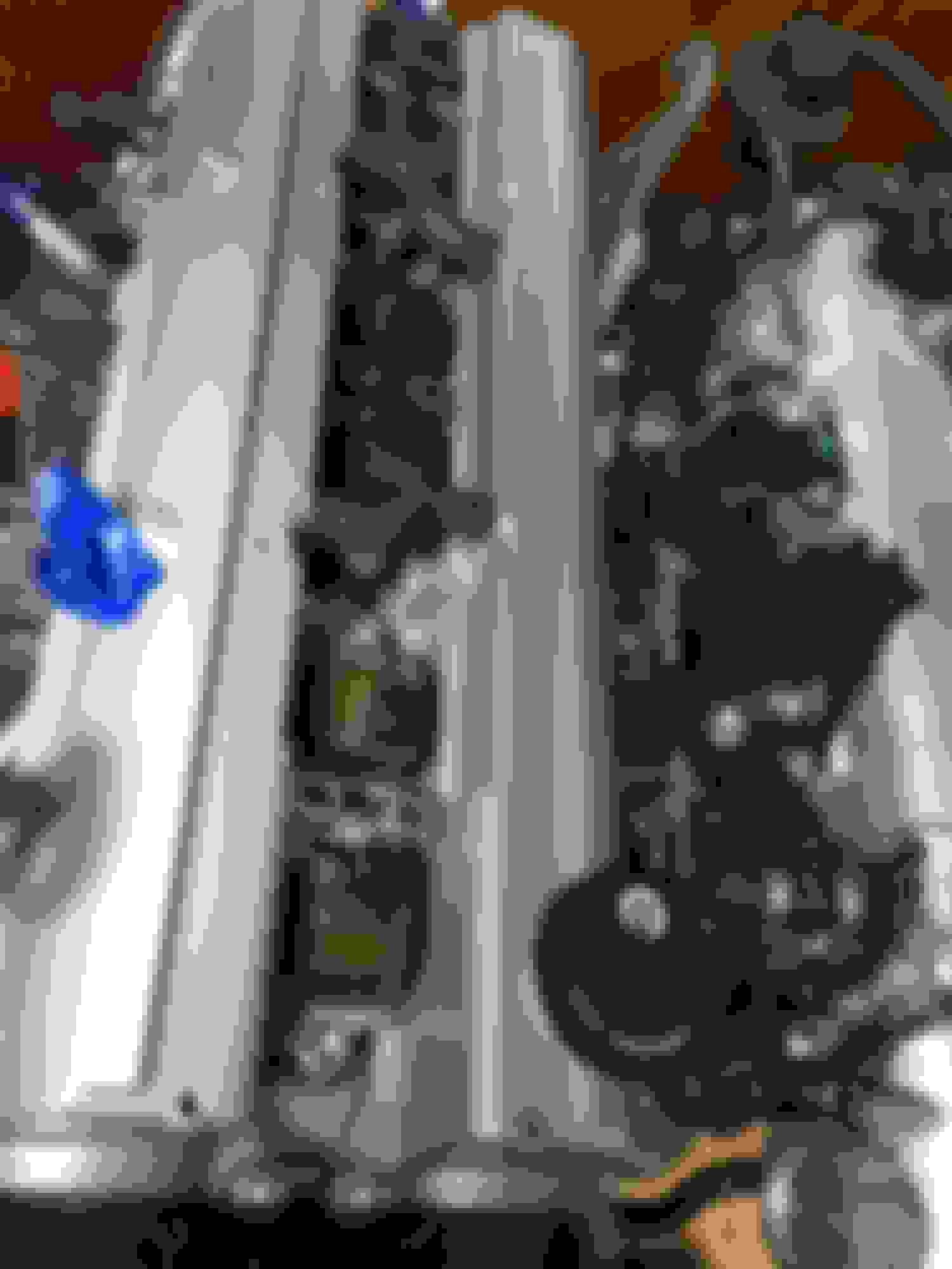
I had NO idea what this pipe was for when I first saw in in my parts pile. I'm glad I didn't have to find one. This goes around the rear of the engine at the top of the valve covers and connects the Idle Air Control Valve's main coolant connector (the largest one it has) to one of the largest coolant bypass hoses on the factory sequential twin turbo assembly... which I believe then has to do with the water cooling of the turbochargers.
Nothing special here but the bracket did take a little experimentation to figure out which way to orient it. This bracket is NOT strong. It's actually very flimsy and you have to make its clamps a little tight to decently hold this pipe in place once you set it in.
Also, note the built in metal vacuum lines on this pipe. Those will be addressed later.
Sorry, I didn't grab a picture of the pipe sitting in place. There will be more pictures of this on the engine later.
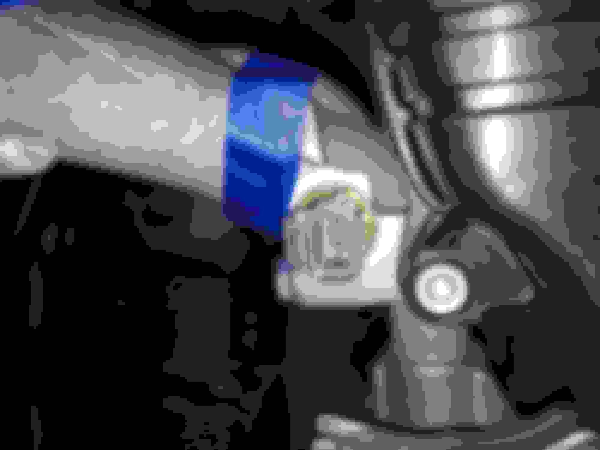
Note: in one of the vacuum ports on this cross-back IAC-V pipe there is a little white inner plug. Someone must have inserted this to go single turbo with the car it was originally a part of. I carefully removed that with some pick tools and tweezers.
Edit: This little inner plug (yellow in the picture) may actually be a stock Toyota part which has no P/N. Its function may be to limit manifold boost pressure going to the TT EGR vacuum modulator and TT EGR VSV so that they both function normally. If this proves to be correct, DO NOT throw yours out as I did. I may have to find a replacement for the one I threw out mistaking it for something a previous owner installed in order to plug that little pipe.
In fact, I encountered an MKIV TT owner who did this same thing assuming that the little yellow plastic insert was a non-factory addition. His solution for replacing this (which I have now adopted) is brilliantly simple: a similarly sized little plastic insert from a "Clean Click" ballpoint pen.
Last edited by KahnBB6; 04-13-18 at 01:20 AM.
Reason: Added solution to replace yellow plastic EGR Vac Modulator restrictor that I had mistakenly removed.
I saw this in an exploded parts diagram as something going onto the water pump and I went ahead an ordered it. I had no idea what it was for or what it went to. As i have learned, it doesn't go to anything! It's just to provide an extended leakage area for the GTE water pump's relief valve should that ever be activated. Mostly it directs drainage away from the alternator and more directly to the engine's under tray.
One thing I wanted the option for on this car was an analog electric oil pressure gauge.
To do this, the easiest way is to use a connection from the oil filter area using an IS300 union bolt (90401-19008) and then an adaptor in order to convert the odd 1/8 BSPT thread to a more common for the USA 1/8" NPT thread.
For this I used an Earl's #968698
The 0-150PSI oil pressure sensor from Prosport Gauges is P/N #PSSMOPS
That sensor uses a universal connector harness P/N #SMOPWH-PK
I also used some Permatex thread sealant for this.
I'll have to route the connection to the cabin later. I bought a 0-5V oil pressure sensor specifically because Patrick, the designer of the Popformance LXCC controller, specifies all 0-5V inputs for the virtual gauges on that unit.
Lately I've been swayed a bit towards buying an physical and analog VDO Vision Black gauge for my 1.6-DIN stereo area and since that would require its own oil pressure sensor, presumably running more than +5 volts, I'd have to change this out.
If you wanted to just have the option there for later a sensor or a 1/8" NPT plug could be left in that union bolt to always have the option.
When I first installed the TT EGR vacuum modulator I realized it was hanging free. I was missing a bracket to hold it in place. I'm not sure of this but it *might* be the same bracket assembly as for the 2JZ-GE 92-97 engine.
It took a little while for this to arrive (not discontinued) and here it is. Fully assembled pictures in later posts.
Pictured: old used TT EGR vacuum modulator which may still be good and a brand new one.

 09-29-17, 09:53 AM


")