When you click on links to various merchants on this site and make a purchase, this can result in this site earning a commission. Affiliate programs and affiliations include, but are not limited to, the eBay Partner Network.
Oh! So all I need to do is connect the Red-With-Blue Stripe wire from the Heater VSV to SC II1-2 and... that's it? The A/C ECU will get its power signal anyway?
yes as long as those two are also connected to pin 2 of IJ1 ..... it is the pin 2 of IJ1 that connects those two (heater valve and II1-2) to the 10A HTR Fuse.
Craig - I will strictly advise avoid referencing wire colors when you are working with different cars and different year models . IT is very confusing and you are not sure if nobody has ever touched the wiring of an old car. Always trace the circuit diagrams . That will be your best bet and safest way.
Eureka!!! Now I get it! And now I know what that spare wire on SC 1J1-2 is for! Thank you Gerry!!
And yes, I have been slowly but surely learning not to trust the wire colors very much. Every connection I have made has not been based on any wire color... just its pre-determined or traced location. I have just been referencing the colors as best I could... although now that appears to be a moot point.
Kahn, I have some documentation when I did my wiring harness. It may help you out alot. Let me know and I can email it to you
CatManD3W, by all means I'll take any documentation I can get, thank you! I have a good chunk of it figured out and wires transferred (or spliced) already but I am not yet done. You have PM.
I will be working on the harness some more this afternoon but after tonight I will have to put the rest of any work for this wiring and the overall swap on hold until sometime next month. I am amazed that I go this far in such a short period of time
As things stand now I have buttoned up many of the unfinished connections mentioned in previous posts. Thank you Gerry for all your patient help answering my novice questions!!!
At this point things are a bit more confusing and difficult as nearly all the obvious wiring chores are out of the way. Though I am convinced that I am actually working with an OBD2 MKIV TT 6-speed harness. Every time I look for an OBD1-specific wiring path that should not be present on an OBD2 harness... and compare the 1995 OBD1 TT schematic to a 1997 OBD2 TT schematic I can always confirm that what is missing from my harness is consistent with what should be missing from an OBD2 harness. Additionally the diagnostic port and ECU diagnostic pin wiring were all consistent with OBD2. Though there was indeed evidence of previous owner hacking into some harness wires down near the ECU and body connectors though (which I fixed/restored easily).
Thankfully I have learned that a USDM 2JZGTE 6-speed harness is not very different from OBD1 to OBD2 mostly with the exception of the diagnostic port to ECU wiring. The main engine sensor wiring should be identical and only a couple of ECU pins are different... all of which I have changed to OBD1 spec (I think).
As far as I can tell in my case the critical diagnostic parts left do address are:
--Installing Diagnostic Port VF1 wire, connecting that to ECU connector ECU E9 Pin #29 and to SC 1K1 Pin #3. Originally this pin was connected to ECU E10 Pin #8 (SDL) for OBD2 communication so I moved it to E9-29... however from the factory this wire was/is also connected to MKIV IJ1-9 with a shield wire end that covers it into MKIV IJ1-6... and no connection to anything on the Diagnostic Port. In the OBD1 schematic it doesn't appear that a shielded wire is needed for the OBD1 style VF1 connection, so I am considering just removing the factory wire entirely and creating my own from scratch.
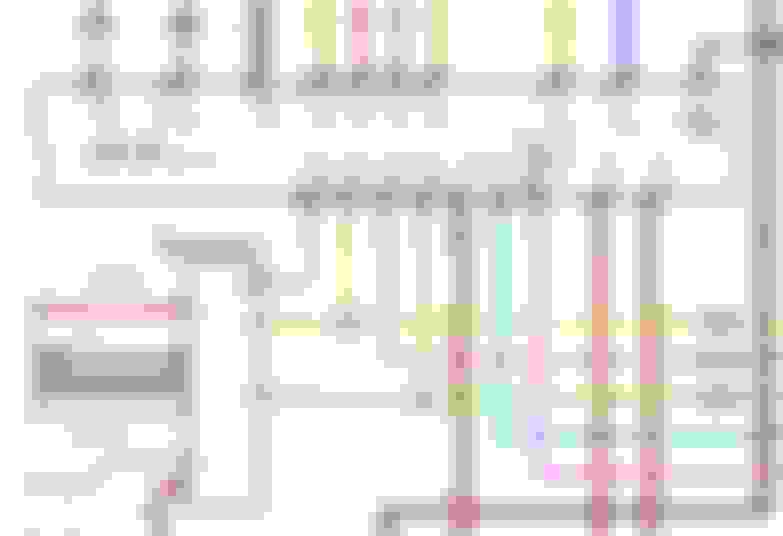
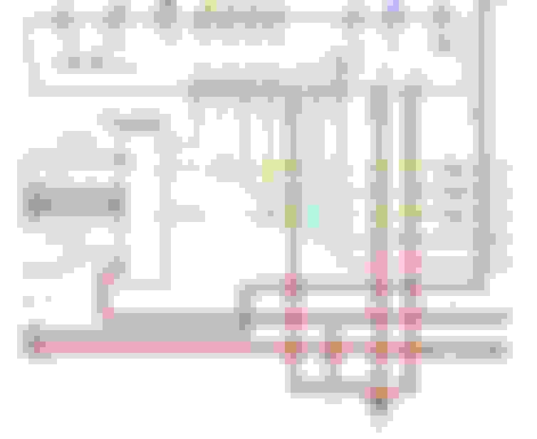
Here is a snapshot of the VF1 OBD1 wiring path (that I DO want):
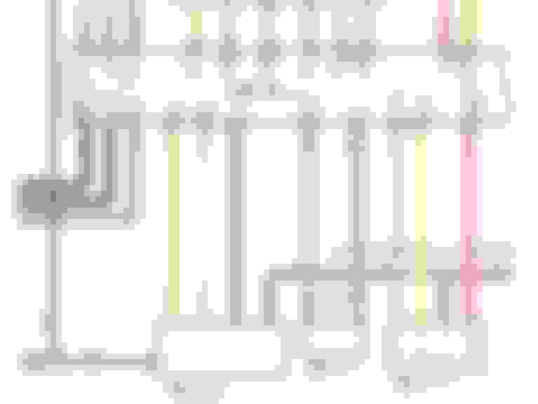
And here is a snapshot of the OBD2 style E10-8 (SDL) wiring path (that I have but DON'T want):
Additionally I am having trouble with part of this bit of wiring because when I followed the USDM MKIV TT OBD1 to SC OBD1 wiring table I was instructed to take MKIV Supra IJ1-13 and connect that wire to Lexus SC IK1-3... which I did. However now that I know this very VF1 Diagnostic connection is supposed to go to SC IK1-3 I have a problem because MKIV IJ1-13 on an OBD1 harness apparently isn't used for the same thing as it is used for on an OBD2 MKIV harness at IJ1-13. I have traced this wire partway into the harness and it *appears* to be going to a sensor connector onto the engine-- I have to test almost every plug's electrodes to figure out where it is supposed to go.
Further adding to the fun, when I pull up the 1997 MKIV TT wiring schematic and search for "IJ1" I have not found any reference to "IJ1-13"! This one wire may in fact not be useful at all for my application but I can't discover what it is supposed to be for on a USDM MKIV TT OBD2 harness so I am reluctant to just discard it until I do.
...
Next, when I go into the factory 1995 USDM MKIV TT "Troubleshooting" TSRM I see references to a few pins that I am still missing (or almost have wired) on the diagnostic connector:
--TE1 (Wired in: to SC IK1-4 & 40-Pin ECU Connector Pin #20 & Diagnostic Port)
--TE2 (Wired in: to SC IK1-2 & 40-Pin ECU Connector Pin #19 & Diagnostic Port)
--W (Is this needed for standard OBD1 diagnosis?)
--E1 (Have a pin for this but it does not connect to the ECU or any body plug, just to somewhere in the sensor area of the harness)
--VF1 (this was absent from the connector... I have pre-plumbed my own pin and lead for this connection through the harness)
--VF2 (this was also absent from the connector... I have pre-plumbed my own pin and lead for this connection through the harness)
--OX1 (Not yet pre-plumbed with a wire... not sure of the gauge required... requires shielded wire)
--OX2 (Not yet pre-plumbed with a wire... not sure of the gauge required... requires shielded wire)
--IG (Not yet pre-plumbled with a wire. Looks like this would be thick gauge with a big spade? Also not yet sure where this would be connected to)
And maybe additionally, (but I'm not yet sure of it), "TC"...?
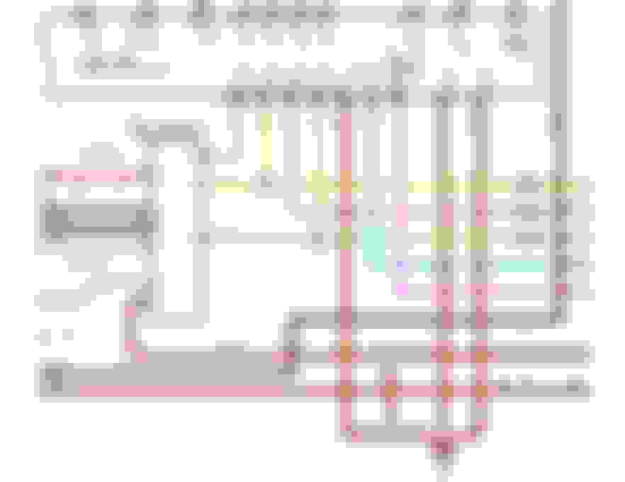
I know that the "OX1" and "OX2" pins are related to the oxygen sensors on OBD1 and VF1 I do have the wiring path figured out for. For the OBD1 setup (that I DO want), VF2 appears to go straight to the ECU at E10-28. When I traced ECU E9-28 and looked it up in both the OBD1 and OBD2 wiring schematics I found the brown wire goes to the last pin on the MAF connector in both versions.
So With the VF2 function it appears that the ECU needs to see that signal from the MAF at Pin 28 and for the Diagnostic Port I need to splice into that wire that goes between the last pin on the MAF connector and ECU E9-28.
(Diagrams below are for the OBD1 wiring):
BUT... when I then look at how the OBD1 Diagnostic Port "E1" wiring is set up, the easy part of it looks to be connecting it to ECU E10-69... but the rest of its path is an absolute maze
Edit/Correction: I actually DO have an "E1" terminal/wire in the diagnostic port but it does not connect directly to any part of the ECU or any MKIV body plugs from what I can ascertain. Looking at these schematics again I think this "E1" terminal MAY actually be okay as-is. Not sure but upon second look... maybe?
I performed a continuity test between ECU Connector E9-69 and the "E1" pin on the Diagnostic Port and I did get a signal confirmation, so this particular pin may be OK it seems.
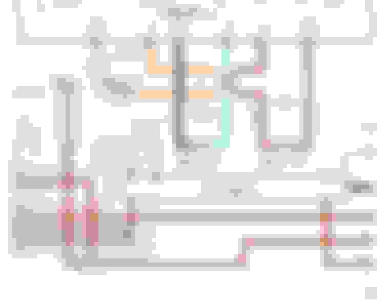
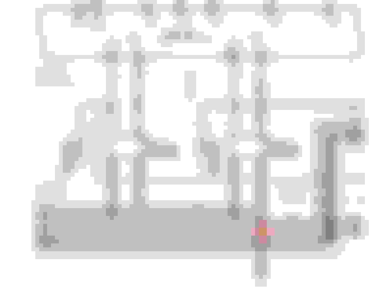
(OBD1 schematic showing Diagnostic Port "E1" wiring path):
And here is what I can find for the OBD1 "OX1" wiring to the Diagnostic Port, ECU and elsewhere:
And The OBD1 schematic for the Diagnostic Port "OX2" wiring path:
I'm going to focus on what is easy to finish up for tonight and I think that may be just verifying (again) that my #1 O2 sensor connections are all correct... and focusing on how to custom wire the OBD1 #2 O2 sensor which apparently has no direct path in the MKIV TT harness.
....
Driving the SC today in warm weather reminded me once again why I am doing all of this: it needs more power!
And once it has more power it will get a more appropriate 3.76:1 final drive ratio.
Last edited by KahnBB6; 01-11-18 at 11:02 PM.
Reason: Much additional progress update info & documentation
I routed a very long 14ga wire from SC IJ1-9 ("Theft Horn") through the main firewall grommet and set it along with the Ambient Temp Sensor wire (SC II1-1) and the big gauge SC IJ1-12 ("Fuel Pump B+") wire that all go into the engine bay for their hookups.
I also found that two spare OEM thick gauge repair wires would serve to fill Diagnostic Port "OX1" and "OX2" (the repair terminals I used were both 82998-12340). They are both green but I will make them work. Only issue I can foresee is that these must both be shielded so maybe I will have to change them out before finishing them up and figuring out how to wire them in.
I have yet to find a spare terminal end I can use to fill the "IG-" connection on the Diagnostic Port but I did learn something about how it hooks up:
According to this diagram (below and a closer view below that) from the MKIV TT OBD1 wiring schematics it gets a signal "From Igniter". Not sure how to interpret that yet but as far as I know this port does need to be present for regular diagnostics with an OBD1 MKIV TT.
I buttoned up (and wrapped) the harness through the outer section before the firewall. Running through it are the additional wires for direct +12V fuel pump power, Ambient Temp Sensor, Theft Horn and SC Heater Control Valve VSV wiring.
From the Diagnostic Port I have added:
TE1, TE2, VF1, VF2 (wiring only, not connected), and FP.
Reassembled the firewall connector and taped/wrapped it up to the wire shield connector (the bulky connector that is wrapped up with the main section of the harness behind the firewall).
Last will be final soldering, wire setting and tidying before wrapping and protective flex tubing are added to the SC body plugs.
For the remaining unused MKIV body plug wires I guess those should be taped off with labels and pulled off to the side.
How’s it coming along Craig? Been a bit since we have seen an update. Hope all is going well!
Jim
Hey Jim! Thank you! I know it's been a while since I've posted progress. After my very last post I had to pause my SC project back in January and deal with a family health matter that has involved my moving to Florida for the time being to be closer to them. It's been a stressful and interesting time to say the least
However as of tomorrow I'll now be able to resume getting the swap carried through to completion. The removal of the old engine will begin sometime very soon. For the moment I'm setting up my work table again to complete the GTE wiring harness. I picked up a new factory MKIV connector and repair wires for the #2 under-body O2 sensor, some more replacement GTE coil pack connectors with repair wires and an MSD Tach Adapter that will all get soldered in.
Then it will be time to put the harness on the engine and continuity double check all the connector pins with the engine sensor connectors
And I think I should buy a new MKIV TT Koyo Race radiator. My old Koyo definitely has developed some pinhole leaks. It would be silly to chance a brand new engine with a leaky radiator. Aside, Koyo makes what looks like a replica of the OEM MKIV TT steel radiator-- does anyone have an opinion on that one vs the aluminum Koyo or aluminum MKIV TT Mishimoto radiators?
Now that Florida is getting into the hot weather season and the 2JZ-GE pulls timing more frequently during the day it's a no-brainer to get this show on the road!
...Just as soon I install a window A/C unit in the garage to keep the humidity and heat away while I work
Actually that was easier than I thought it would be once I figured out the orientation of the harness on the front of the engine.
Getting it installed revealed more broken connectors and weakened electrical tape coverings that needed repair but these were minor to address.
At current count I just need to replace two injector connectors, the turbo side VSV connector on top of the engine next to the exhaust manifold valve cover (a common connector failure due to heat) and I need to replace and solder in the compromised wires for the oval alternator plug. Those connectors are on order now.
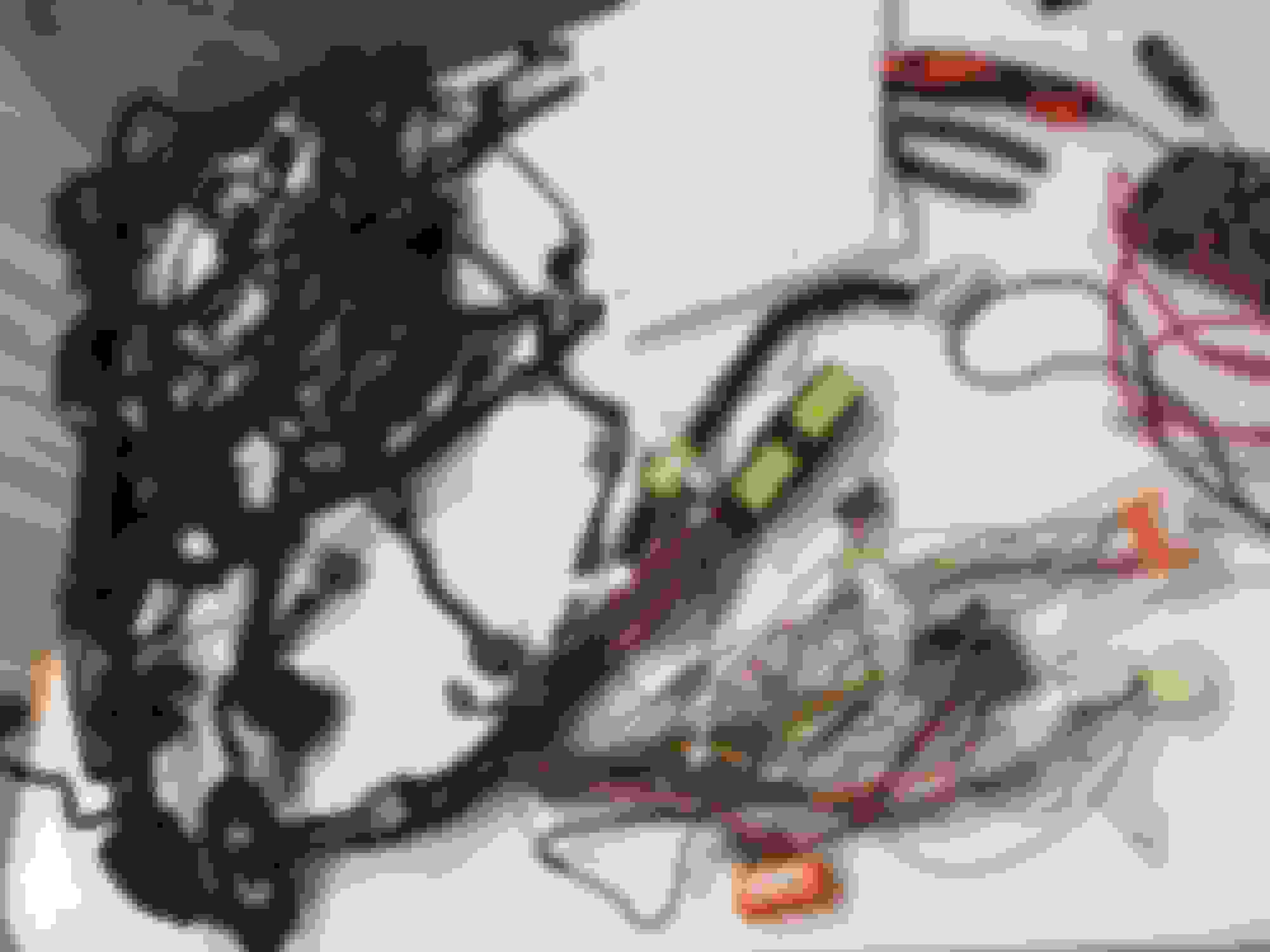
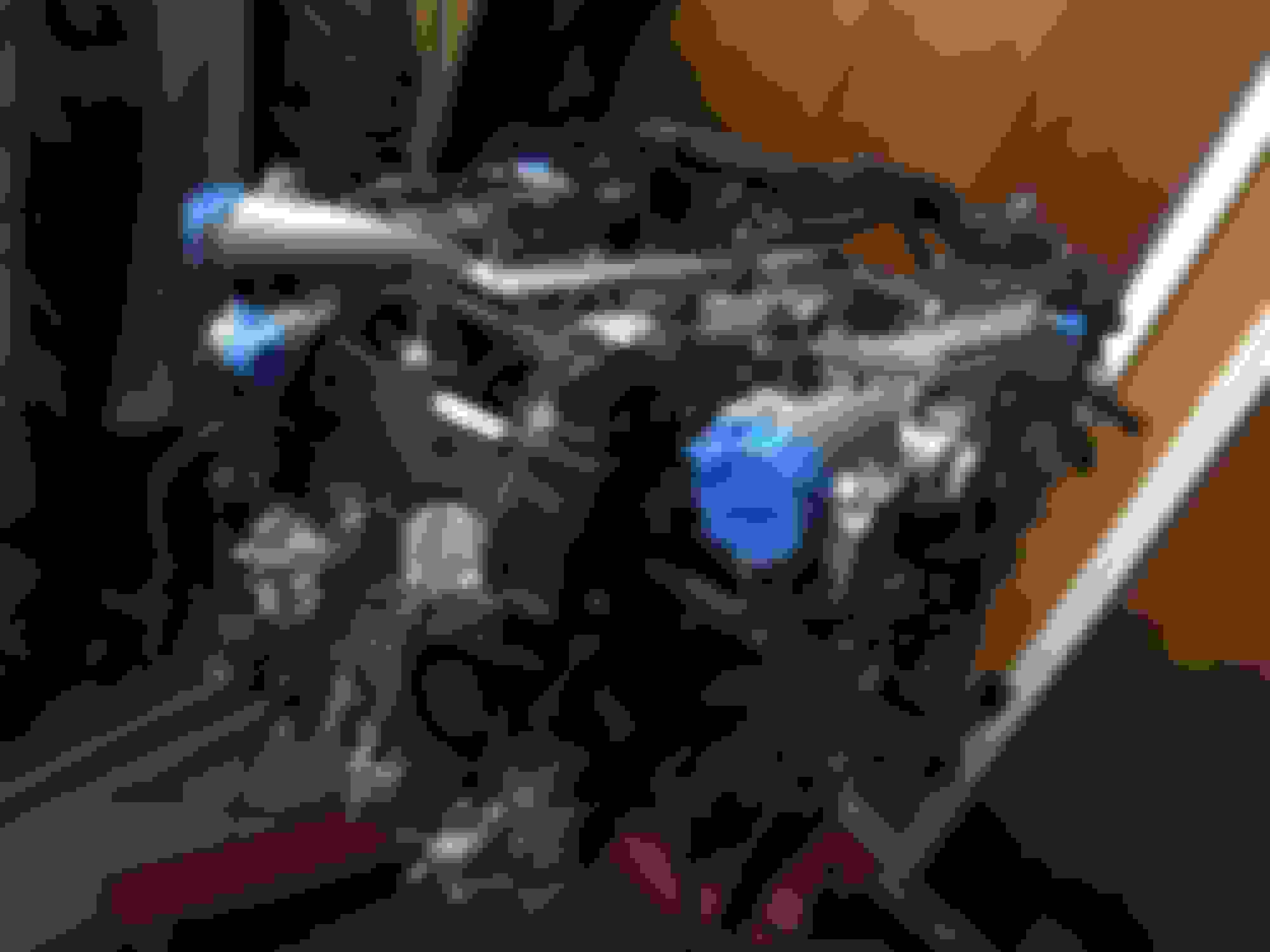
Here are some pictures of how it all looks on the engine thus far (note that the three wires hanging over the throttle body and the SC body plug wiring are not yet taped and covered� that will come next):
The injector plug order I think I got right. The first and last were no-brainers while #2-#5 seemed to follow a logical distance for each wire. All the wires in that intake side galley are a tight fit.
By my count there are two ground wires on the intake side. One I believe goes onto the manifold(?) while the other... I�m not yet sure.
Although here I�m not yet sure what the following connectors do (pictured below).
Since I have not yet installed an A/C compressor or PS pump I know some of them go to those components.
A large cluster of the loom goes to the injector resistor pack area.
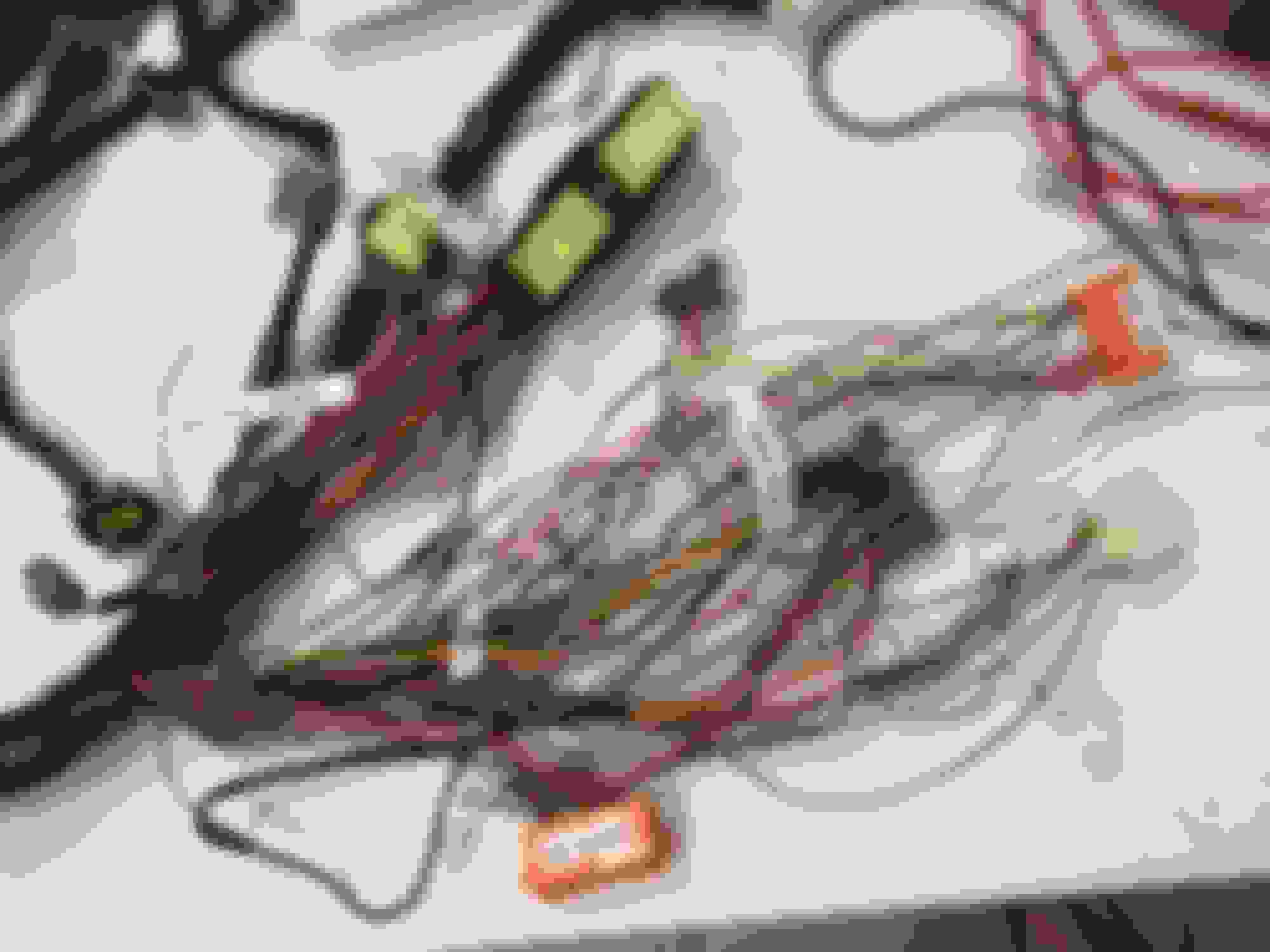
But these I�m currently stumped on:
And this one, I think *should* be the connector for the USDM TT EGR temp sensor... but it does not fit and there was no other leftover connector in that location that would suggest it goes to the EGR temp sensor connector.
Something occurred to me about this:
There may be a difference between 1993.5-1995 OBD1 and 1996-1998 OBD2 with the USDM TT EGR temp sensor's connector and the corresponding USDM TT harness's EGR temp sensor connector. And this TT harness started out as an OBD2 before I converted it to OBD1.
Since I have installed a used TT EGR temp sensor (and I don't know if it was from an OBD1 or OBD2 Supra) it is possible that I have one that isn't compatible with the connector on the harness.
I suspect there is no difference in the sensors themselves other than the connectors used but I'll have to do some research on this. Hopefully I'm actually comparing the correct harness connector!
The injector plug order I think I got right. The first and last were no-brainers while #2-#5 seemed to follow a logical distance for each wire. All the wires in that intake side galley are a tight fit.
By my count there are two ground wires on the intake side. One I believe goes onto the manifold(?) while the other... I�m not yet sure.
one set of ground wires go to the front area of intake manifold and the other set goes to the rear area of intake manifold
Originally Posted by KahnBB6
Although here I�m not yet sure what the following connectors do (pictured below).
Since I have not yet installed an A/C compressor or PS pump I know some of them go to those components.
A large cluster of the loom goes to the injector resistor pack area.
But these I�m currently stumped on:
backup light and speed sensor of your 5 speed trans
As soon as I read your response I had a three Homer Simpson "D'oh!" moments
But that's good... I've got all the connectors are where they should be. I'm feeling very good about the motor now. It's almost done and ready to be moved to the workshop to get installed.
How are you doing? Things have settled down now and I've wanted to check in and see what you've been up to since I last saw you in GA.


 01-10-18, 02:00 PM