When you click on links to various merchants on this site and make a purchase, this can result in this site earning a commission. Affiliate programs and affiliations include, but are not limited to, the eBay Partner Network.
Been doing good , thanks buddy . Trying to spend less time and work less on these SCs so I can wind down to 2 or 3. You know how it goes ... the more you work on them , the more it gets addictive and you want to keep them all .
The two 1997 SC300 5 speed are all stock now. If they don't sell at the prices I want now, I would put them in a bubble .. in the barn down south and let maybe 10, 15 or 20 years pass and see what happens. I have nothing to loose on them. Soon I will be done too with my Ultimate SC Sleeper ... the red mamba with the stroker 3.4 . I have yet to find some more parts like Gen 2 PT-7685 and another SP quick spool valve at a good price. Got my Motec ECU and 6 thermo couples with their Motec Thermocouple amp. I got an exhaust manifold from my buddy Jared of Speed for sale that has bungs on each runner for thermocouples.
Glad things are better on your end . Installing the harness specially if the engine is on the bay , it is much better taking out the 5 bolts and 2 nuts that hold the intake plenum into the runners , in that way , you have easy access into the injectors. It won't be long , you have your car running .
Been doing good , thanks buddy . Trying to spend less time and work less on these SCs so I can wind down to 2 or 3. You know how it goes ... the more you work on them , the more it gets addictive and you want to keep them all .
I know that is true of my SC I work on it (or drive it) and am reminded why I like to own it. See my last post on your build thread. I'm actually trying to help you find a reason to keep a third one, haha. But finding another unique variant to suggest between the RM2 and OMT is difficult. There is always an SC400 1UZ + 5-speed M/T, a hardtop SC, '98+ SC400 or even an imported Soarer (there's an idea!) but other than those I'm hard pressed to think of a unique different custom build you could do that your other two won't easily cover. There's the STU GT28 hybrid factory sequential twin setup but I know you aren't interested in them for all their limitations. You seemed to like the BPU'd stock JDM 2JZ-GTE automatic car just fine to experience sequential and for serious power you've already got your stroker single turbo engines.
Originally Posted by gerrb
The two 1997 SC300 5 speed are all stock now. If they don't sell at the prices I want now, I would put them in a bubble .. in the barn down south and let maybe 10, 15 or 20 years pass and see what happens. I have nothing to loose on them.
That could do something for sure. I think some more time will be kinder to SC's. Then again it's the same with your MKIV TT's isn't it?
Originally Posted by gerrb
Soon I will be done too with my Ultimate SC Sleeper ... the red mamba with the stroker 3.4 . I have yet to find some more parts like Gen 2 PT-7685 and another SP quick spool valve at a good price. Got my Motec ECU and 6 thermo couples with their Motec Thermocouple amp. I got an exhaust manifold from my buddy Jared of Speed for sale that has bungs on each runner for thermocouples.
I can't wait to see that one finished No doubt we will soon see the new engine bay. You've been gearing up to start tuning with the Motec this summer?
I just got a new R1856 Koyo aluminum radiator from Speed For Sale a week ago. They had it here FAST. I think my old identical one might be fine but I didn't want to take chances with a brand new engine. I was thinking about trying Koyo's C1856 OEM style TT radiator but no one on SF seems to bother with it.
Originally Posted by gerrb
Glad things are better on your end . Installing the harness specially if the engine is on the bay , it is much better taking out the 5 bolts and 2 nuts that hold the intake plenum into the runners , in that way , you have easy access into the injectors. It won't be long , you have your car running .
Thank you! Yes, a lot to do still but getting better.
Yeah, for several reasons I wanted to just install the harness onto the engine before the swap begins. I needed to learn where everything goes with more space to work since I've never done it before. It's also allowing me to fine tune finishing up anything else the harness needs now that I can visually confirm each connector's location on the engine.
For any servicing later on I will know to plan on removing the upper intake manifold. I'm glad I delayed all of this longer by installing all new sensors, VSVs, etc. whenever possible. Some of them are in such difficult to reach places I much prefer to not have to bother with most of them again in the future.
After I finish tidying up and wrapping the SC body plugs and their wiring the next project before the swap will probably be swapping in the TT fuel pump and wiring it for 12V + relay. I'm running out of things on the checklist
I admire you for all that detailed work for a stock 2jzgte swap . A lot of money and time have gone into that project .
Keeping a third SC for good , it remains to be seen . Yeah eventually I will post pictures of the two SCs I am keeping for good. They will definitely stay longer than my MKIVs since I am thinking of cashing in on those Supra 6 speeds once they have reached their peak.
Hopefully , the 1 of 120 1997 SC300 5 speed prices will go a lot higher after they have passed their 25th year anniversary. I don't think they will ever be as in demand as the Supra MKIV 6 speeds which dictated their prices. Being rare though , they probably would go higher than what they are now. The 6 speeds MKIVs are simply in a different league. In a very short period of time , like the past 4 years , they basically doubled their prices. I was just lucky to have had 9 MKIVs in the past 9 years and have kept 4 of the 6 speeds . So until the demand really soar and people are willing to pay , I don't see SC300 5 speed prices going through the roof. The market isn't just there right now and will it ever get there ? who knows... though you hear tons of people wanting a 5 speed SC but not yet willing to pay premium prices.
This project has gone on for so long with this approach just to get a stock rebuilt engine ;D Yes, a lot of time and money just to get it this far. I do think there was still yet an easier/cheaper way to get a USDM GTE configuration (mostly starting with a full Aristo 2JZGTE as a basis for the conversion and not rebuilding it) but I know I'll be happy with the end result. Even though I easily could take it MUCH further than a stock or BPU tune I would only do that with another SC which I don't intend to live under such strict limitations.
I agree with you about the current market. It has already bottomed out but we'll just have to see what happens with the popularity and values of these cars in the future. At current time my long term consideration is through what insurance company I can get a modest agreed value policy after an appraisal (once the car is completed) and whether or not that will even be possible at current time. For Supra MKIV's and Skyline R32 GT-R's and probably Z30 Soarers (and many other special original RHD imports) it's not a question.
I came in here to comment on just how valuable of a resource you have made this thread.
I just finished the motor swap process of putting a 2jz-gte/v160 into my mustang. I also went the route of making it 100% usdm and going through the Bar referee process. I just went to the referee a week ago and got my engine change label put on my mustang. If you have any questions on the process please let me know. I found a lot of the information and part numbers on here very useful.
spd0lit, thank you! I'm happy it has been useful to you in doing basically the same swap for CA. I've been taking so long and it's probably a testament to stubbornness I've started to read through your thread on SF and the work is very impressive! I nearly owned an SN95 Mustang around the time I bought my SC. A 2JZ in one is an awesome combination! I totally understand the sentimental attachment to your first car also. My first was also a Mustang.
I will indeed contact you to ask about your experience with the California BAR referee and registration process and compare notes. I've been in touch with a couple of referees over the last few years to iron out specific questions with them and a couple of other CL and SF forum members have also gone through this process since I started building the GTE engine. I don't have to worry about it for the time being but the BAR process is still the plan and goal for this car.
And thanks! Yes, I'm getting very close now. I'm waiting on help to be available to begin the physically intense stage of the swap but in the meantime I'm taking care of as much harness/electrical work as I can and I'll likely buy a couple of new front accessories for the engine (less to swap over from the 2JZ-GE) before it goes in.
More updates and pictures to come! The latest/next will be some more minor engine wiring harness repair and finishing up the protective coverings for the SC body plugs and their wiring.
Truly however I will quickly run out of things left to install, change or repair if I don't get it underway very soon Although as Gerrb has pointed out to me, the installation and and prep-for-igntion stage will be intense on its own.
Previously I was so focused on getting the body plugs rewired for the SC chassis that I missed a few broken connectors, some of which needed their terminals replaced, which I'll detail below:
1993-1995 MKIV TT OBD1 EGR Temp Sensor body harness connector:
The part number for this is a 90980-10899 for OBD1 USDM TT harnesses. For MKIV TT OBD2 harnesses it is 90980-11273. The terminal ends, if needed, are the same for all years: 82998-12440.
Also, though they are now discontinued by Toyota, the TT EGR temp sensors themselves are different part numbers (with different connectors) for 93-95 OBD1 and 96-98 OBD2.
Aftermarket alternatives for both versions are still sold:
I have both versions in my spare parts and I have not had a chance to test to test them yet but I suspect that just the EGR temp sensors may *possibly* produce different resistance ranges that each respective OBD1 or OBD2 TT USDM ECU wants to see.
...or it could be that since the EGR system is basically the same from 1993-1998 TT models it's just the connectors that are different. At the time of this post I honestly do not know, so my build focuses squarely on using the part numbers that Toyota designed for the OBD1 Supra TT's.
On the TT EGR temp sensors themselves, the replacement connectors are:
93-95: 90980-10898
96-98: 90980-11272
TT IACV VSV connector:
So I understand, since this VSV connector is right above the twin turbos, even with the heat shield and rubber protector boot it has a tendency to develop stress cracks over time. Thankfully the terminal ends for mine were in very good condition.
Most of these were fine on my harness but the only issue I had with the broken ones was the locking-click tab. Unfortunately even if the rest of the connector is on the fuel injector, in an engine compartment with regular NVH I can easily see one of these broken ones sliding loose, thus rendering a cylinder non-fueling. Probably a very bad thing
So, preventative replacement it is.
I first ordered a couple of replacements (which included terminal wires) from Driftmotion. One of my old connectors also had bad terminal ends so I needed to cut and solder those in. The other damaged connector still has good terminal wires and is so tight to get to (with the harness on the engine) that it made more sense to replace just the connector.
Now here is where this gets interesting. Driftmotion sells somewhat generic Toyota replacement injector connectors for both "top" and "bottom" injectors. What this actually refers to is where the guide tabs on your fuel injectors are located-- nearer to the top or nearer to the bottom of the area where the connector slides on.
Further, there has been some discussion on SF about USDM 2JZGTE harnesses using the factory 550cc low impedance injectors actually could have used different connectors over the production run.
For my harness, which I know was from OBD2 TT Supra, the connectors were: 90980-11153.
I have also read of a 90980-11154 mentioned but I cannot confirm since I just ordered the part number from the broken connector that I removed.
This last week in the evenings I've been completing the wrapping and protective covering of the SC body plug wiring. I needed to realign, shorten or lengthen a few wires in certain places so as to keep the wire length on each bundle mostly uniform.
Where once this was a big mess it's now quite tidy! Although I hope I haven't made the overall bundle too thick to get through the firewall opening and tight passages. On most of these I opted to reuse flexible plastic protective hose from both the MKIV and spare/cannibalized '97 SC Auto harness. And plenty of Scotch Super 33+ electrical tape.
What's left now? I need to set on generic connectors to the harness wiring for the MSD Tach Adapter and give it +12V and Ground, figure out what connector(s) I want to use to hook up the four wires for the #2 O2 sensor connection and eventually wire in the three custom wires I plumbed through the harness on the engine bay side for +12V fuel power, SC Ambient Temp Sensor (for the A/C) at EB1-7 and the SC's Theft Horn connection.
You'll notice there is one plastic flex tube right front and center in these images that has no connectors on it. This represents all the unused MKIV harness wires or one or two that were relevant for OBD2 but not for OBD1. I labeled them all with their original connector locations, put electrical tape on each wire end and bundled them all together to be set aside. This is perhaps not the cleanest way to finish a wiring harness but I didn't want to unwrap the entire thing for fear I'd never get everything exactly back to factory lengths and bends.
With a fully custom harness I think it would be very unwanted to have extra unused or never-to-be-used wires.
Figuring out how to wire in the 2JZGTE A/C electric helper fan
While I wait on other things for the swap I'm going to start figuring out how to wire in the early version MKIV TT A/C electric helper fan. It's not really required depending on how the car is used and in what average temperatures but since I do foresee this car seeing heavy stop and go traffic and sometimes very hot days in excess of 90 degrees, I think it applies in my case.
The earlier TT helper fan setup is a single fan on the driver's side of the TT radiator shroud. The later 96-98 version is two smaller staggered electric fans on the same side of the shroud.
The fan is supposed to come on only when the coolant hits 212F and higher and shut off once the temperature drops below 192F. The tricky part of wiring it is that it's supposed to connect solely through an MKIV TT's body harness and not any direct part of the engine harness.
Thankfully since I have the earlier 1993-1995 version, this applies from post #27 of the thread linked below:
Ishi's statement is probably true for 97+, but for the pre-facelift TT Supras, which only have one small helper fan in the shroud, the ECU and A/C are not directly involved in the decision...only that lower coolant temp "switch" and the 2 fan relays.
The OEM sensor that goes into the bottom of the MKIV style radiator is likely a digital one rather than analogue even if there if no direct ECU connection through the MKIV body harness on the pre-OBD2 versions. Still, there are one or two relays involved. I will update this post with the connector and terminal wires needed to plug into the MKIV TT electric A/C fan itself.
This thread has given me some ideas but I think I need something simpler since I am not running a PRO EFI or other aftermarket ECU:
But this thread seems to be more succinct than all others in detailing how the factory aux electric fan system is supposed to work (although I believe this references the 1996-1998 twin aux fan system it is only the principles of operation which are described and that seems to be similar for all years unless the 1993-1995 single aux fan system only has one fan speed rather than two):
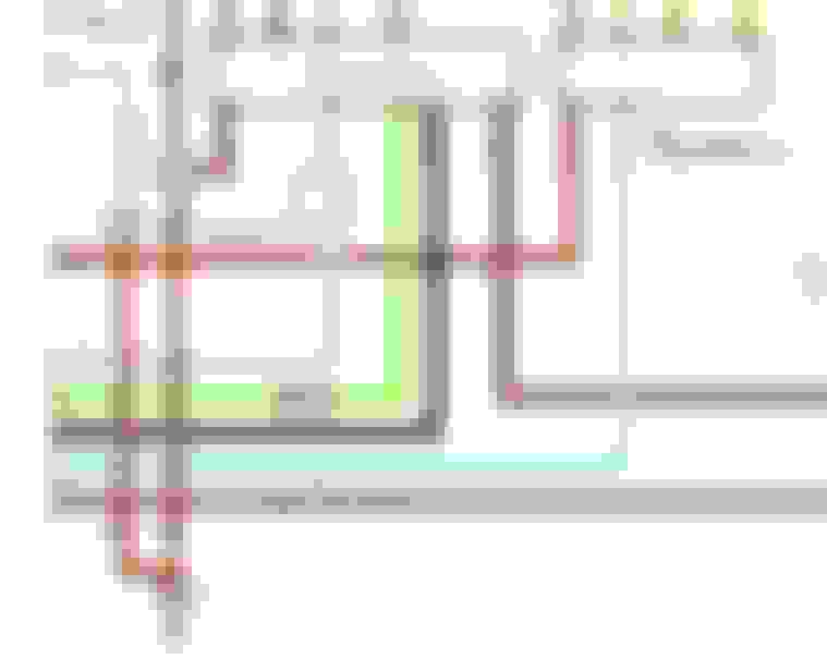
Below is a simplified wiring diagram for the 1995 MKIV Supra TT that detail the A/C helper fan system. However I am not certain but this might be for the later twin electric fan configuration which if so... doesn't apply here. I may be incorrect but I think this shows *two* electric "motors" (aka fans): one intended for the radiator and one for the condenser. I assumed the twin fan electric helper fan system only came in 1996-1998 MKIV TT's but maybe they showed up as early as the 1995 model year?
The key difference is that the early single fan system should have no direct connection to the ECU, just two relays and the sensor in the radiator while the later twin fan system should have a connection to the OBD2 ECU.
To connect the early style fan to the electrical system I ordered a 90980-11237 connector and two 82998-12480 terminal repair wires which include weather seals on each. These are THICK gauge wires. I'm not sure of the gauge right now but I will measure and update this post with that information.
More on this soon as I learn how to do this either the Toyota way or possibly in a simpler way that achieves the same function.
Last edited by KahnBB6; 04-04-18 at 02:39 PM.
Reason: Updated with additional information, pictures and an electrical diagram
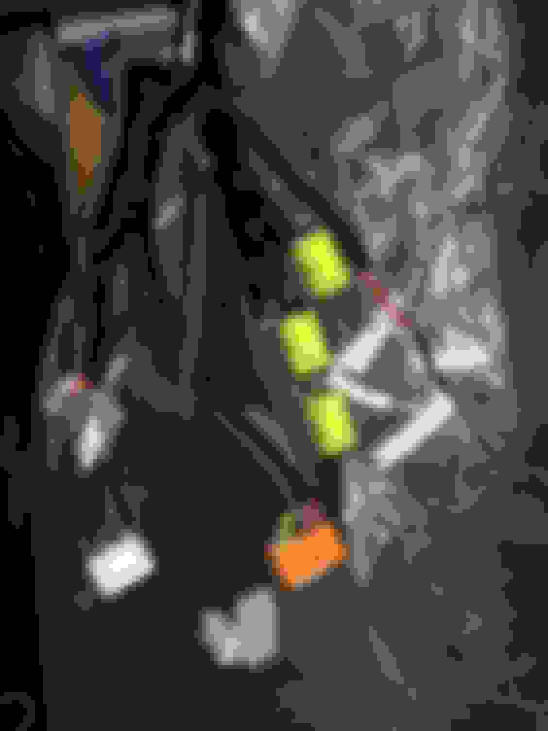
This connector was cracked on my harness so I replaced it with a new 90980-11156. The original connector was black but this replacement is a bright white. Kind of annoying as it's the only bright colored part on the upper engine and really distracts from the rest of it but it's a brand new part for an early 90's engine so I can't complain. Interestingly this VSV connector is almost the same as the many gray replacement VSV connectors for the turbo side. The feed/guide is just reversed.
USDM 2JZGTE (Stock) Engine Harness Finishing: Direct wiring for #2 O2 sensor & MSD Tach Adapter
With the harness nearly finished and at Gerrb's suggestion thinned out a bit to fit the connector side through the firewall by removing all my extra flex tubing and re-wrapping it was time to build some connectors for the last two stragglers.
TT USDM 2nd O2 sensor:
This is not often retained on many GTE swap cars since they either never came with a need for one (JDM) or the build is not going to use it anyway. For smog check compliance with a USDM 2JZGTE it's required.
Function-wise it does NOT control the engine operation in any way. It just checks the operation of the 2nd catalytic convertor and reports the ranges it is calibrated for back to the stock ECU.
Connection-wise it is tricker. The USDM Supra TT IJ1 and IJ2 body connectors normally route these connections from the engine harness but the early Lexus SC300 has no immediate connection between the ECU and physical #2 O2 sensor connection plug... at least on Federal models.
Since my car is an original Cali-Spec SC300 and all 1993+ Cali-Spec SC300's *DO* have a 2nd O2 sensor that does this same ECU reporting function I think my car may have this wiring... however it is not immediately apparent as to where to find it once you go deeper than the (Cali-Spec only... not included on any Federal pre-96 cars) center console O2 sensor connector on the side of the firewall.
Back in 2011 I made a thread detailing where the under-body O2 sensor is on the 1993-1995 Cali-Spec OBD1 SC300's (since this thread refers to *three* O2 sensors, remember that the USDM GTE has only one front O2 sensor but the USDM GE has two front O2 sensors):
And in that thread I show where that sensor connector routes through the transmission tunnel under the car with a grommet on the sensor wire and comes up to the driver's side of the trans tunnel underneath the center console where an opposite end O2 sensor connector is waiting for it.
Now this being the case with my Cali-Spec SC300 I feel that if I knew where this harness actually went to I might be able to verify that the connect pins on the chassis-side body connectors are there for me to have put these wires into their respective SC body connectors on my custom GTE harness.
However when I pulled up my carpet the other day to look at the ECU and body plug area I just could not find any wiring that looked like it traced back to the transmission tunnel on the driver's side. Maybe when I get my swap underway I will discover where my factory SC #2 O2 body connector routes to.
In the meantime I have planned to make my own direct wire harness with a second set of male and female O2 sensor connectors. A pro-tip here is that if you have to do this step for your own swap, get an old O2 sensor and steal the connector with terminal ends from it to make your extension harness to the transmission tunnel O2 connector. The connectors are cheap from Toyota but most places the O2 sensor side terminal repair wires are EXPENSIVE... as in nearly $20 each expensive at standard MSRP. I bought mine in a rush locally and by now I should have known better than to not check pricing ahead of time to find a cheaper place to get them. However I did need them quickly...
Now the pinout for the O2 sensor I got from this link on SupraForums. I assume that this is accurate for my application but if it is not, someone please correct me. I've already soldered the wiring as of this posting so I hope I got it right
(Note: After reviewing both the 92-95 SC300 Cali-Spec wiring diagrams and the 93-95 MKIV TT wiring diagrams I have corrected these pinouts as of 7/21/2018)
From that thread the pinout for the connector as:
Pin 1 -- "HT" ---- O2 Sensor ECU Ground
Pin 2 -- "B-R" --- O2 Sensor Heater Power
Pin 3 -- "OX3" -- O2 Sensor Signal Wire (on OBD1's, shielded at about 2-3" up from each connector; has additional shield block wire on OBD2's)
Pin 4 -- "BR" ---- O2 Sensor Heater Ground
And from my own USDM GTE engine harness to SC300 wiring notes I have the following in quotations with my determination as to which pin each wire should be routed to... which I hope I was correct about:
Pin 1 -- "O2 Heater Ground to ECU"... from MKIV body connector IJ2-5 ("Brown/White" wire)
Pin 2 -- "ECU B+ Out to 2nd O2 & O2 Heater +"... from MKIV body connector IJ1-20 ("Red/Black" wire)
Pin 3 -- "2nd O2 Output To ECU"... from MKIV body connector IJ2-14 ("Black/Red" wire)
Pin 4 -- "Ground for 2nd O2"... *spliced* from/with SC body connector IJ1-18 ("Brown" wire)
Additionally, for those who have a 1992-1995 Lexus SC300 California-Spec chassis, this is the pinout that I have traced so far for the direct connections for these under-car O2 sensor wires that interface with the existing plug and ECU pins. Please be aware that the pinout below will ONLY apply to an OBD1 1992-1995 SC300 California Emissions model which came with the 3rd O2 sensor prior to model year 1996:
Sub-Oxygen Sensor Pinout SC300 California-Spec 1992-1995 (from SC300 Wiring TSRM Page 138 and Supra TT Wiring TSRM Page 72):
1 -- "HT" --------- Lexus IK2-22 ------- Supra TT IJ2-5 (Brown/White) -- O2 Heater Circuit (Ground to ECU)
2 -- "B-R"/B+" -- Lexus ??*NOTE* -- Supra TT IJ1-20 (BlackRed) ---- From ECU B+ Out to O2 Sensor AND to O2 Heater +
3 -- "OX" --------- Lexus IK2-12 ------- Supra TT IJ2-14 (Red/Blue) ----- O2 Sensor Output to ECU
4 -- "BR"/"E1" -- Lexus IK1-1 --------- Supra TT IJ1-18 (Brown) --------- Ground Connection to O2 Sensor
***Note: For Pin 2 of the connector, when studying the SC300 92-95 TSRM which shows the California Emissions SC300 model's 3rd Oxygen Sensor wiring (aka the under-car "Sub-Heated Oxygen Sensor" which is exactly the same principle as used in the MKIV TT for its under-car Sub-Heated Oxygen Sensor) I was unable to definitively trace where this wire terminal should go. I followed the "B-R" wire path until I eventually found it made a connection with SC IJ1-12 but I was not sure if this is 100% correct. IJ1-12 in the SC300 is also part of the main EFI power wire path.
As of 7/21/2018 I have not yet definitively figured out where to put this wire from the Supra MKIV TT engine harness into the Lexus body connectors under the dash... and so I stayed with my direct wire patch harness for my under-chassis Sub-heated Oxygen Sensor connection which has worked for me.
However it would be best to know where all four wires are supposed to go so that any 1992-1995 SC300 California Emissions chassis can re-use the pre-existing wiring for the 3rd O2 sensor connection.
Now I will emphasize, as Gerrb drilled into me over this whole wiring process... do not base your wiring decisions on the colors of the wires themselves... because they tend to vary from harness to harness and year to year. While there are some commonalities you'll always be surprised by there being no easily predictable logic from Toyota if you go by wire colors. Stick to the pinouts only. I have retained the wire color suggestions from a wiring guide but they aren't 100% so just follow pinouts only.
For reference, here are the relevant TSRM Wiring pages showing the wire paths for this sensor.
(In these diagrams you are looking for "oxygen sensor sub" or "sub-heated oxygen sensor" or "Sub O2" or in the case of the SC300, sometimes "OX3")
For the 1992-1995 SC300 California Emissions models (Wiring TSRM Page 138):
And from the Supra MKIV Twin Turbo Electrical Wiring TSRM (Page 72):
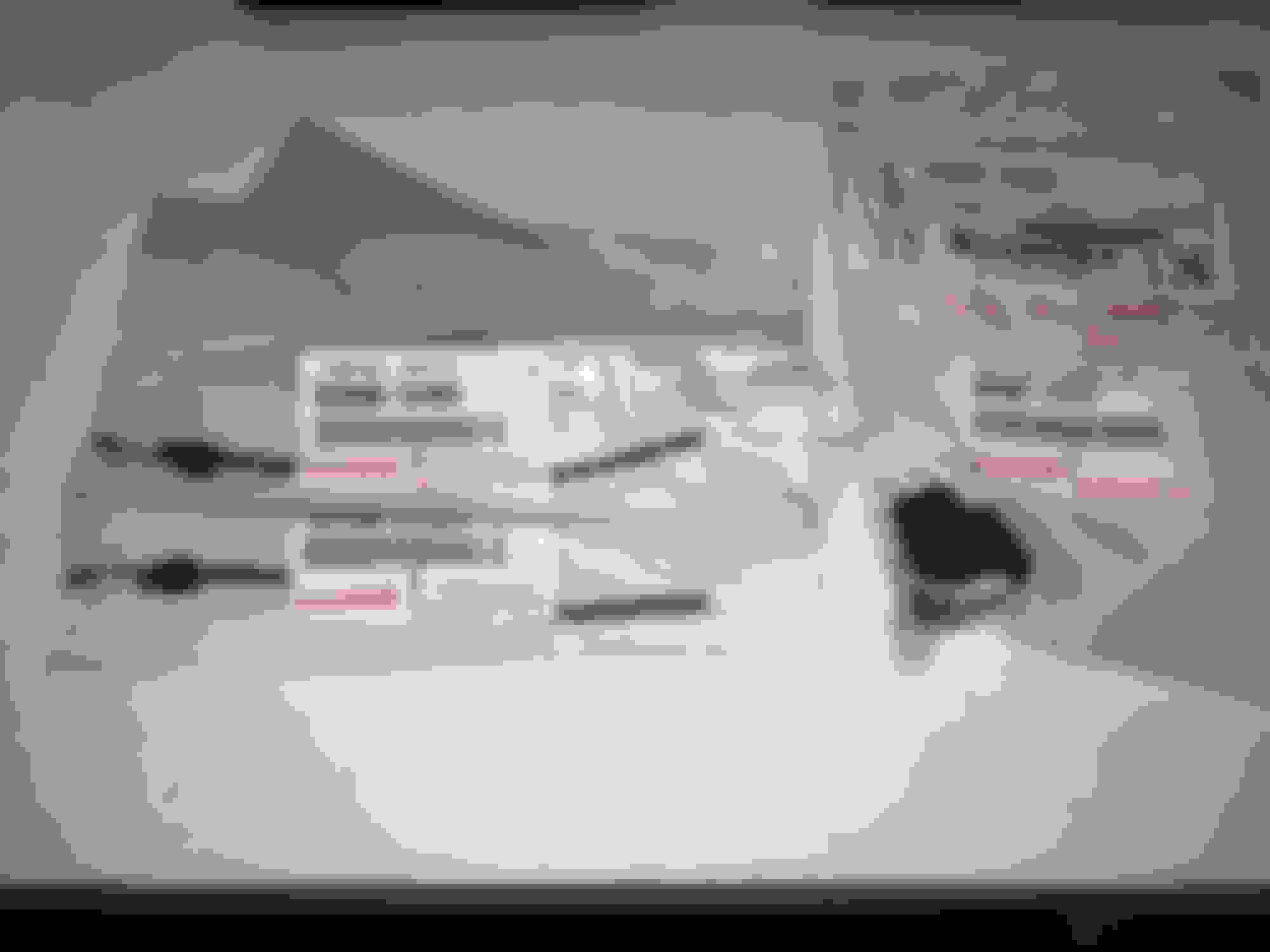
Here is the result of creating the first part of a 2nd O2 direct wire setup from the engine harness:
^^ You can see that my Pin 3 O2 sensor signal wire (the shielded one) has the OBD2 style extra terminal end extending from the shielding that is intended to be plugged into a spot on a connector that goes to a shielding block of some kind. This is another leftover aspect of my USDM TT OBD2 harness that I will not be using for the OBD1 TT spec I have converted it to.
I think I can just snip this off and use electrical tape but someone please correct me if I am wrong!
Also, I am wondering if I need to procure a little extra shielding to cover up as much extra unshielded portion as possible right up to the connectors themselves.
OEM parts used for this part of the project (this side does not use the expensive terminals):
For the rest of the extension harness I cannibalized O2 sensor wires and a 90980-11028 connector and terminals from the spare '97 SC300 Auto harness that I've been taking things from. This includes one shielded wire for the O2 sensor signal. That covers the end that goes to the side of my trans tunnel.
To plug into the engine harness 90980-11028 connector I needed to recreate the connector end of an O2 sensor.
These were:
x1 90980-11027 connector
x4 82998-12430 terminals (shop around for these... they are NOT cheap at about $20 EACH!!)
I needed these soon and so I ordered them locally. I assumed that because the terminals for the other side were only $6 each they would be the same. What I would recommend is to take a bad/old Toyota Denso O2 sensor with the 11027 connector and just steal what you need from that. I did not have an old one handy.
I've set these parts aside for now. Once I get the GTE engine harness into the car I will know how long I need to make the extension harness for the direct connection to the 2nd (under body) O2 sensor.
......
Connection to MSD Tach Adapter
Next, made a simple quick disconnect for my MSD Tach Adapter connection to the harness with a set of repurposed Molex connectors:
For this, the wires used are:
MKIV body connector II1-29 "TACH IN" (meaning tach signal into the MSD)
SC body connector IK1-8 "TACH OUT" (meaning the converted MSD signal to the tachometer)
On the MSD Tach Adapter itself there is a +12V Power and a Ground wire that connections have to be located for under the dash.
The other connector end wires I will splice into the MSD once I have the harness int he car and have a good idea of what the wire lengths need to be.
Last edited by KahnBB6; 07-21-18 at 09:49 PM.
Reason: Added pictures and additional information
As of yesterday I've encountered a good deal of misfiring from my original 251k mile 2JZ-GE such that it's now time to begin the swap since I don't consider that old engine very drivable at this point at least when accelerating. Whatever that longstanding startup issue was, now it's finally started to affect normal drivability... two whole years after it first made itself known.
After my warnings from oil samples I sent Blackstone Labs in 2016 it took this long for the issue to truly affect the engine's everyday health. That's quite excellent I'd say. If I had intended to keep and rebuild the 2JZ-GE and boost it instead of the 2JZ-GTE I know it would still be good for it. But for a totally untouched engine that has has nothing more than maintenance and stock replacement parts that sees little more than 6-7k miles per year and has otherwise performed flawlessly and reliably... I'm quite happy with my experience using an NA 2JZ for the last eight years. I'll be a little sad to see it go
USDM 2JZGTE Gauge Water Temp Sensor to SC dash water temp gauge
For a while I've been concerned about how to deal with this issue in the best way. Vigman with his USDM 2JZGTE swap eventually ran a separate water temp gauge and sensor altogether. Gerry tells me he hasn't had issues with the dash temp gauge with all of his swaps. Then for the longest time it has been suggested to use a 330 Ohm resistor in line with the dash gauge connection at the SC body connector IK1-9 (which for this swap was supplied with the wire from MKIV body connector II1-9).
However in my searches I also came across this link which seems to offer a much simpler solution and a reason why GTE swaps into SC's have trouble with their dash temp gauges:
Therein, the poster states that the issue arises from different grounding methods for the dash temp gauges between GE and GTE cars (or SC's and Soarers and MKIV's).
A discrepancy here: while my swap guide and notes suggest that this connection for OBD1 SC's is at SC IK1-9, this poster suggests the solution is to add a ground to a specific SC IK2 pin.
I have not yet gone into the schematics to test his theory. Personally I'm trusting the pinout guides I've already consulted for my harness work which point to IK1-9 but further investigation will be needed and soon.
Thoughts on either shrink-tubing as-is or re-soldering (and shrink-tube covering) the +12V fuel pump direct power wire
A few months back when I was converting my harness to use SC body plugs I made sure this thick gauge wire was routed through the harness past the firewall area. I stole it from my spare 97 SC300 Auto harness in as much length as I could gather.
It has these factory clamped connections throughout which were originally mean to connect to other wires that needed +12V power but all I need to do is cover them up. My concern is if I should just pass heat shrink tubing over the exposed clamp connections or should I cut them here, strip the wire ends and solder them together before applying heat shrink tubing.
I'm normally a proponent of soldering everything but Toyota viewed those crimps as suitable throughout the harness. I'm not aware of any issues with them failing. I'd just leave them alone and be sure I covered them well with heat shrink.

 03-12-18, 03:27 AM

 .
. . I have yet to find some more parts like Gen 2 PT-7685 and another SP quick spool valve at a good price. Got my Motec ECU and 6 thermo couples with their Motec Thermocouple amp. I got an exhaust manifold from my buddy Jared of Speed for sale that has bungs on each runner for thermocouples.
 . Installing the harness specially if the engine is on the bay , it is much better taking out the 5 bolts and 2 nuts that hold the intake plenum into the runners , in that way , you have easy access into the injectors. It won't be long , you have your car running .