When you click on links to various merchants on this site and make a purchase, this can result in this site earning a commission. Affiliate programs and affiliations include, but are not limited to, the eBay Partner Network.
You'd think there would be SOME way to adjust brightness being LED and all. This thing is really coming together Craig!
Thanks Rudy! Yeah, you would think, right?
I only have a guess that the SC�s instrumentation brightness dial and the way that overall circuit works has a lot to do with the independent Illumination 12V+ and Illumination Ground/Negative wires.
Or... it�s even simpler: the LED backlight inside that gauge is not dimmable. Just the same as with household LED bulbs if you buy one that isn�t a dimmable type it�s not going to adjust its brightness when you turn a dimmer dial or switch. It will just turn on when the minimum required current is applied and turn off when the current falls below that minimum.
I hope everyone is safe and protected with all the recommended sanitary precautions right now while we’re all locked down due to this virus.
Not a fun time right now. I am wishing everyone wellness and safety.
....
I revised the gauge layout yesterday, jacked up the front of the car and got behind the wheel well cover to run some more wires and integrate them into my accessory harness with new connectors housing more pins.
After lots of work and Scotch Super 33+ electrical tape I got everything tidied up again and wired together my boost sender.
I do like this layout much better. It does make practical sense to have the volts, oil pressure and oil temp readouts in one location (plus now all those gauges match in their uniform backlighting) and the boost gauge near the main cluster instrumentation.
The needle registers positive boost and goes back into vacuum so quickly that there really is no other location where it makes sense to put it.
...
Now there is one issue I am having. Perhaps it’s not an issue at all though. I’m not sure.
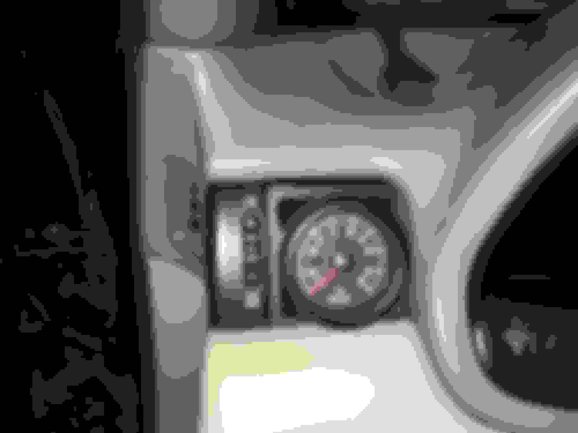
According to the Prosport boost gauge the 1st turbo only registers only 5psi even when I’m pulling hard up to 3500-4000 RPM (since I now know that my 2nd turbo is shot I am staying out of it while in sequential mode).
If you look at the picture of the boost gauge above, where I observe maximum boost up to 3500-4000 RPM is at the “5” marker. I think I *should* be seeing it at or just before the “10” after that “5”, correct? Because you should be reading vacuum (ie: well below the "0" on the gauge's scale) until you build boost and gain positive pressure in the intake.
It's almost like the scale is off... but that cannot be the case... can it?
Either my pressure tap location on the intake manifold isn’t good enough or the Prosport’s boost scale on the gauge face isn’t compatible with how I’m hooking it up.... or perhaps my 1st turbo wastegate is getting stuck at 5psi when it should be maxed out at 10 psi?
(Remember that the full stock boost 10.5-12psi is only supposed to come when both turbos are online).
I can definitely say that the engine does NOT feel lacking in power in the lower RPMs at all. It feels perfectly healthy and very strong and powerful.
My 2nd turbo replacement needs to be addressed later but that’s a separate issue (my spare rear turbo is currently awaiting a rebuild at a specialist's. I'm sending the spare front turbo in for rebuilding after that one is done).
Does this sound right to anyone? I thought that with the stock sequential system active the #1 CT12B (USDM) or #1 CT20 (JDM) would go to between 8-10psi before the 3800-4000-4200 RPM #2 turbo transition.
that's been on my list, keeping factory radio (pioneer in my case) and integrating bluetooth and an antenna up/down function on two of the radio's buttons.
Thanks! Independent antenna up/down function is what I have wanted for a while now. It was fine to switch between the AM/FM modes and CD (Reading "CD ERR") for aux-input because the stock head unit would make the antenna go down whenever you left one of the two radio modes.
When I went with an aftermarket head unit even when I combined it with the pricey Beat-Sonic SLA-10B adapter kit the stock antenna would always stay up when the head unit was powered on and the stock/OEM Pioneer amplifier and sub-amp (both of which I am still using now with my setup) got their amplifier remote power on signal.
Only turning off the car entirely makes the antenna go down. Turning off the aftermarket head unit does not do it.
.....
That's where Raine's great DIY thread comes in handy. He shows you how to bypass three wires to the factory Pioneer sub-amplifier (the wiring is under the package tray and it's a chore to take lots of things out just to get to it) in order to tie them all together to run a long remote-power-on wire directly from the aftermarket head unit.... or if like me your aftermarket head unit has no remote power on wire (German designed aftermarket head unit weirdness) you can wire up the same signal by using a cheap PAC TR4 module to generate that same signal and trigger it from your radio powering on.
Right now my manual up/down switch is only limiting the antenna from going up whenever the aftermarket head unit is turned on. As soon as I flip the switch to complete the circuit the antenna goes up... but flipping the switch back down again to break the circuit does not make it go down. Only turning off the car will do that... for now.
.....
After studying Raine's thread I searched for and bought another blown/junk SC Pioneer sub-amplifier on ebay and raided it for its connector. Then I noted the part number on the connector that goes into it on the body harness and bought a couple of OEM replacement wires and raided some more spare OEM terminal pins with wire gauges of the same size as the ones on the body harness side and made myself a patch harness with the three wire bypass built in.
You do not need to do it this way. My way is added expense. In Raine's instructions he shows you how to do exactly the same thing by cutting the wires right on the SC's stock body harness connector for the OEM Pioneer sub-amplifier.
The little circuit interrupt switch will actually do its full job once this extra three wire bypass is done as per his instructions.
My extra work to make a patch harness just makes everything really neat and plug and play. I like almost everything electrical on my car to be clean, reversible and serviceable with this approach but it could be considered overkill I suppose.
I haven't installed this harness yet because... well... I need a non-rainy day when I'm not otherwise busy to take apart the back seat again and test it. That's my entire excuse really. But according to Raine's instructions this should work and allow true manual up/down control of the factory aerial antenna.
.....
Here's a picture of the Pioneer sub-amplifier patch harness I made according to his instructions. I have a super long coiled length of amp turn-on wire which will need to be run from the package tray area of the SC's back seats all the way to the front console radio area.
(This is the custom-made plug-and-play patch harness I made to go between the SC's body harness at the package tray area and the connector on the stock Pioneer sub-amplifier in that location. Note the three bypass wires tied into one very long coil of wire. This has to be run all the way from the package tray to the front console radio area where an independent amplifier turn-on signal is supplied.
I need to work on making my tight space patch harnesses much shorter. And don't pay attention to the wire colors on this custom made harness-- the pin locations are all that matter. I couldn't justify the expense of all new terminal repair wires from Toyota (well... I bought three of them and that was costly enough added with the spare connector) so I just used what I had laying around in spare Toyota harness wiring bits and terminal ends to complete this. Remember that the female connector end required buying a whole blown OEM Pioneer sub-amplifier off ebay just for that part).
I am also holding off because I want to know exactly what cables and wires I will need run back there into one of the trunk pass-through grommets to give myself backup camera pre-wiring for the OEM 1992-1996 spoiler. That's another project for a later date but I want to set the long wires up for it early if I'm going to take the back seat apart anyway to finish the antenna control wiring.
Completing the harder and more time consuming parts of little mini projects like this often get shoved onto the back burner until there is a good day to get out there and do it.
Originally Posted by babycrab
keeping factory radio (pioneer in my case) and integrating bluetooth and an antenna up/down function on two of the radio's buttons.
I did this exact thing with my stock Pioneer stereo. I did the aux-in jack DIY modification, threw on a right angle stereo jack adapter, a ground loop isolator and installed onto that a stealth Bluetooth handsfree audio interface device that hid behind the stereo.
Might I recommend an iSimple Tranzit BLU-HF module? It's a little pricey but it worked very, very well for me and proved very reliable. Only a couple of times did I have to do a hard reset of the device's stored memory by physically accessing it or perform the same reset via their iPhone app. Their handsfree unit also includes a microphone and a little almost OEM looking telephone answer/end-call button that you can affix to the front of your OEM Pioneer head unit.
It handled Bluetooth audio music streaming from my cellphone very well.
Until I got myself an aftermarket head unit with these functions built in I swore by that little module.
thanks for pointing me to raine's thread, I was unaware the lexus special interest forums existed.
with the iSimple transit unit behind the radio, how did you pair devices and also select for the radio to be playing off the bluetooth unit?
No problem. The forums split up some specific stereo DIY topics into that specific sub-forum independent of the Lexus models.
With the iSimple BLU-HF unit once it�s installed and hooked into your OEM head unit�s DIY aux-in jack you just pair with it from your phone�s bluetooth menu.
There is a downloadable app (ios and android) that allows finer control but generally all you need from it most of the time is to audibly hear it beep confirmations through the car�s speakers.
I should still have mine in a box. I can shoot a few pictures of it.
The only modifications I made to it were a couple of mini Molex quick disconnect connectors.
sounds like a great solution, better than what I had in mind originally.
sure send some photos over!
the diy aux input thread I found by user pieisgude had its photos removed. is that the guide you followed?
I believe it was, yes. The pictures have been removed now? Yikes! Well, I still have my stock head unit stuffed into a corner. Worst case I could pull it out and take some pictures of the internal modification if there is no current frame of visual reference. There wasn't a whole lot to it, really as I recall. It's just a factory set of test pins that gets tapped into inside the stock Pioneer head units.
The 1/8" stereo jack is a cheap and common radio shack (or other generic similar) part. Then you just use a 90-degree angle 1/8" stereo adapter and onto that you plug into some brand Ground Loop Isolator (Radio Shack or other brand, it doesn't matter) which then gets plugged into whatever your audio source should be.
I'm fuzzy on what he said about getting the CD changer into "CD-ERR" mode but that's the most reliable way that worked for me. My tape deck was always perpetually jammed and I could never stay in tape deck mode for more than a second. Eject mechanism issue. Therefore in my case I'd always use the "CD" button since my CD changer never worked either.
The DIY aux-in mod will allow you to play your source audio onto ANY of the stock Pioneer stereo source modes (AM, FM, TAPE, CD) but you want either TAPE or CD in a permanent state of non-operation (though with the head unit allowing you to *stay* in TAPE or CD mode) so that you have a clean input channel for your aux-in sound via cable or Bluetooth module.
since I don't have a cd player, it appears i'd have to put a dummy tape into the deck in order to select tape mode.
well thanks again for the info, I won't hijack your thread further lol
Wow, you have one or the rare cars without the CD changer option! Very cool!
In your case, yes you need to put a dummy tape into the deck so that it is always in �Play� mode. Once your tape ejects that sound source cancels and the head unit reverts back to an FM or AM radio source.
As requested, here is my old stock Pioneer head unit with the auxiliary-in DIY mod and the iSimple Tranzit BLU-HF Bluetooth A2DP streaming audio and handsfree phone module and all its wiring, the microphone and phone answer/end button that I affixed to the front of the stock head unit. I added the molex quick disconnect plugs myself.
I also opened up the case to show the little sound test port that is used for the Pioneer stereo aux-in DIY.
You can see that I picked up a generic small electronics connector with three wires. One wire is the left channel, the other is the right channel and the third wire gets grounded to the head unit�s chassis. I drilled a hole in the chassis just big enough for the Radio Shack 1/8� stereo jack and soldered the L & R channel wires onto its terminals after testing beforehand to be sure each was going into the right channel post.
(*There is also another hole that was drilled but not used. Way back when I originally did this modification I made a mistake in where I wanted the jack to be mounted. A good lesson in �plan/measure many times and cut/drill once�.)
Thanks Rudy! That stock head unit and the Bluetooth setup are both old news now for my car (both still in perfect shape, I just moved on).
I happened to have the HU handy in a box to snap a few pictures of the aux-in DIY. I�ll post them in that DIY thread since the original pictures have gone offline.
^ Always appreciated by many! I did the Aux input on my stock head unit and am so glad I bothered. My car is purring like a kitten right now! I need to figure out how to get the AC relay wired up for the Aristo ECU still, but otherwise, I simply can't get enough of driving it. I'm planning on filling it up today and heading to the mountains to go cruise for an hour or two to get out of the house.
^ Always appreciated by many! I did the Aux input on my stock head unit and am so glad I bothered. My car is purring like a kitten right now! I need to figure out how to get the AC relay wired up for the Aristo ECU still, but otherwise, I simply can't get enough of driving it. I'm planning on filling it up today and heading to the mountains to go cruise for an hour or two to get out of the house.
This sounds like a great idea! I hope you were able to get out there and enjoy a little driving this afternoon! The Aristo A/C clutch wiring fix hopefully will not be all that different for a GTE VVT-i ECU. At least in Florida I wouldn't last more than a week without getting my A/C sorted out.
...
I spoke to a Prosport Gauges rep today and the boost gauge accuracy issue may have something to do with either the signal line I ran from the engine bay into my dash, the +12V power source and ground used to power the sender, the boost sender itself or barring all that the gauge itself. I've run some tests and have to run several more to nail down what the issue is but it may indeed be a signal line issue.
With the ignition set to ACC or with the car started the boost sender signal wire should read 1.0 volts to the gauge. At ignition "ON" I got 1.0 volt at my multimeter but once I switched to "ACC" I read a constant 0.86 volts. I'm beginning to wonder if the switched +12V cigarette lighter circuit that I pulled my power from is being taxed so as to cause this... but the main +12V and Ground wires coming from that circuit to my boost gauge power read a consistent +12V.
Additionally I tried out Prosport's "Premium" boost sender that I'd also bought but didn't use. I hooked its power up directly to the battery and hooked it into my firewall snaked signal wire going to the gauge. Same exact readings as before.
So now I'll have to test my +12V wiring going to the boost sender for a consistent +12V and I'll have to bypass the signal wire running through the dash with another wire to the outside of the car going directly from the gauge to the boost sender. Then I'll be able to rule out the last remaining electrical questions about this.
The last resort would be if the gauge itself has an issue but that +0.86 volt reading at the signal wire when it should be +1.0 volts before the car is turned on has me suspicious.
At the Prosport rep's suggestion I used my Mityvac hooked up to the boost sender directly (did this with both of them) to simulate both engine vacuum, engine in boost and the engine off at "0" between In-Hg and PSI. Here are some pictures for reference comparing the gauge on the Mityvac and the electrical boost gauge's reading. Something is definitely off.
That is so weird, my digital boost gauge in my audi has been doing similar.... might have to check the voltage like you pointed out although I noticed I crushed a small part of the vacuum line some.
Hopefully you get it sorted out, that is a little annoying for sure. I might have to go back to mechanical lol

 03-24-20, 06:40 AM