Kahn's USDM 2JZGTE swap thread (aka The "Not Easy" Way)
#961
Pole Position
You're the man, as always Craig!
#963
Pole Position
TBH I think I've just got a bad check valve maybe. I've got my VSV bypassed to test, but it snowed over the weekend so she's at home tucked in the garage until the roads clear a little lol. My GF always says "get that ****box out of the garage and enjoy it more"! haha.
#964
This is the location of the three way vacuum splitter that I was referencing. It replaces the screw-in part that your FPR VSV vacuum line feeds from.
This is where I run a long Gates vacuum line from to connect onto the SC Heater Control Valve VSV’s check valve.
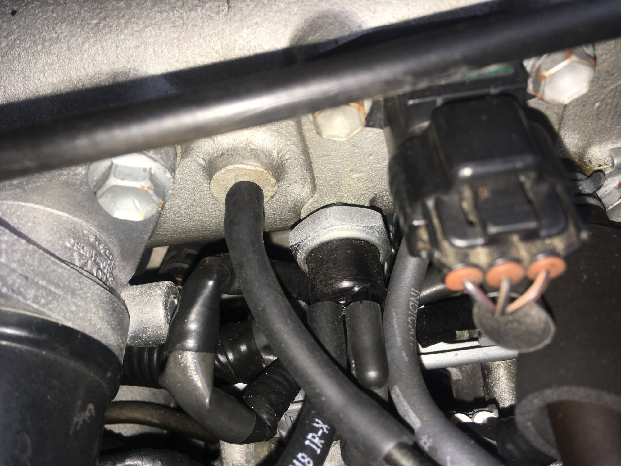
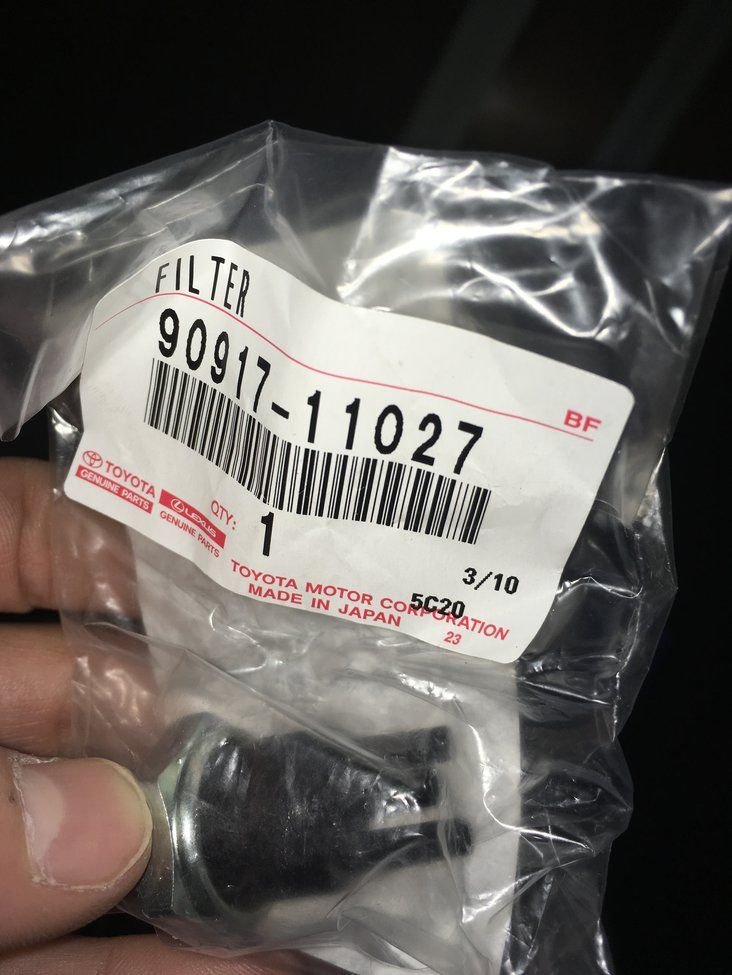
Edit: And the Toyota part number for that three-way vacuum splitter is 90917-11027
Last edited by KahnBB6; 01-25-21 at 01:12 AM.
#965
Pole Position
Craig - I've got that picture saved and a note made on your build thread! That's a great idea and will most certainly come in handy!
#966
What gauge are the original battery cables? I quess the point in using two cables in parallel is to split the current in to two cables. However the thicker gauge will have less resistance and therefore carry more current (assuming both cables have equal length). But the fuse should still be selected according to the cable with the smaller gauge (or separate fuses for both wires). Lets say there is a 200 A fuse and the crimp on one of the cables fails - now the other one is carrying all the current and if it is the one with the smaller gauge it may not handle the current (original fuse is 120 A) and cause a fire.
I admit this is a problem only in the worst case scenario. The 2/0 gauge cable alone should be sufficient to carry the current.
I admit this is a problem only in the worst case scenario. The 2/0 gauge cable alone should be sufficient to carry the current.
#967
What gauge are the original battery cables? I quess the point in using two cables in parallel is to split the current in to two cables. However the thicker gauge will have less resistance and therefore carry more current (assuming both cables have equal length). But the fuse should still be selected according to the cable with the smaller gauge (or separate fuses for both wires). Lets say there is a 200 A fuse and the crimp on one of the cables fails - now the other one is carrying all the current and if it is the one with the smaller gauge it may not handle the current (original fuse is 120 A) and cause a fire.
I admit this is a problem only in the worst case scenario. The 2/0 gauge cable alone should be sufficient to carry the current.
I admit this is a problem only in the worst case scenario. The 2/0 gauge cable alone should be sufficient to carry the current.
The original battery positive from the alternator (unless it's split into two 10 Gauge wires deep within the run across the radiator the same as the MKIV Supra) looks to be an 8 Gauge or 6 Gauge wire but I am not certain of this.
Yes, the basic idea is to put much thicker and finely wound electrical cables at the main charge and ground points to allow for bigger pipes for the main electrical current to flow.
And I do have a 200 Amp inline fuse with holder sized for 2/0 gauge but I haven't used it yet... or installed the cables or alternator yet... more on that in a moment.
I was recently alerted that there actually is a 150 Amp alternator fusible link for the fuse box that was standard in early model SC400's, up from the stock SC300's 120 Amp fusible link. I'm picking up one of those tomorrow to swap in.
My main problem the last time I had a chance to work on the car is that I am having a lot of trouble fitting the absolutely massive 2/0 gauge cables... even though they were made using flexible and dense strand welding wire... at the factory battery terminals. The close proximity to the factory fuse box makes it extremely tight to fit these additional connections in there and cleanly.
Getting them all onto the alternator, engine block ground location and the factory chassis ground next to the battery negative terminal and running them the distances they need to go are the semi-easy parts. It's getting them cleanly onto the battery terminals in such a way that the hood can close that is the difficult thing I am running into.
...
I have called and emailed DC Power to get their opinion about whether or not I absolutely need 2/0 gauge wire or if I can safely drop down to a 1 Gauge or 2 Gauge set of wires. Driftmotion recommended the 2/0 size cables but I feel like they may be overkill for my application. Maybe I'm wrong. This is one area (upgrading battery cables and grounds) that I am not astute about.
In another recent thread Lexforllife told me with his upgraded setup and aftermarket high output alternator he runs 2 Gauge cables.
Whether I wrestle these 2/0 cables into place or have 2 or 1 Gauge cables made instead I will run an in-line 200 Amp fuse on the alternator charge wire and I will replace my 120A alternator fusible link with an SC400's 150A fusible link.
#968
Another long overdue update.
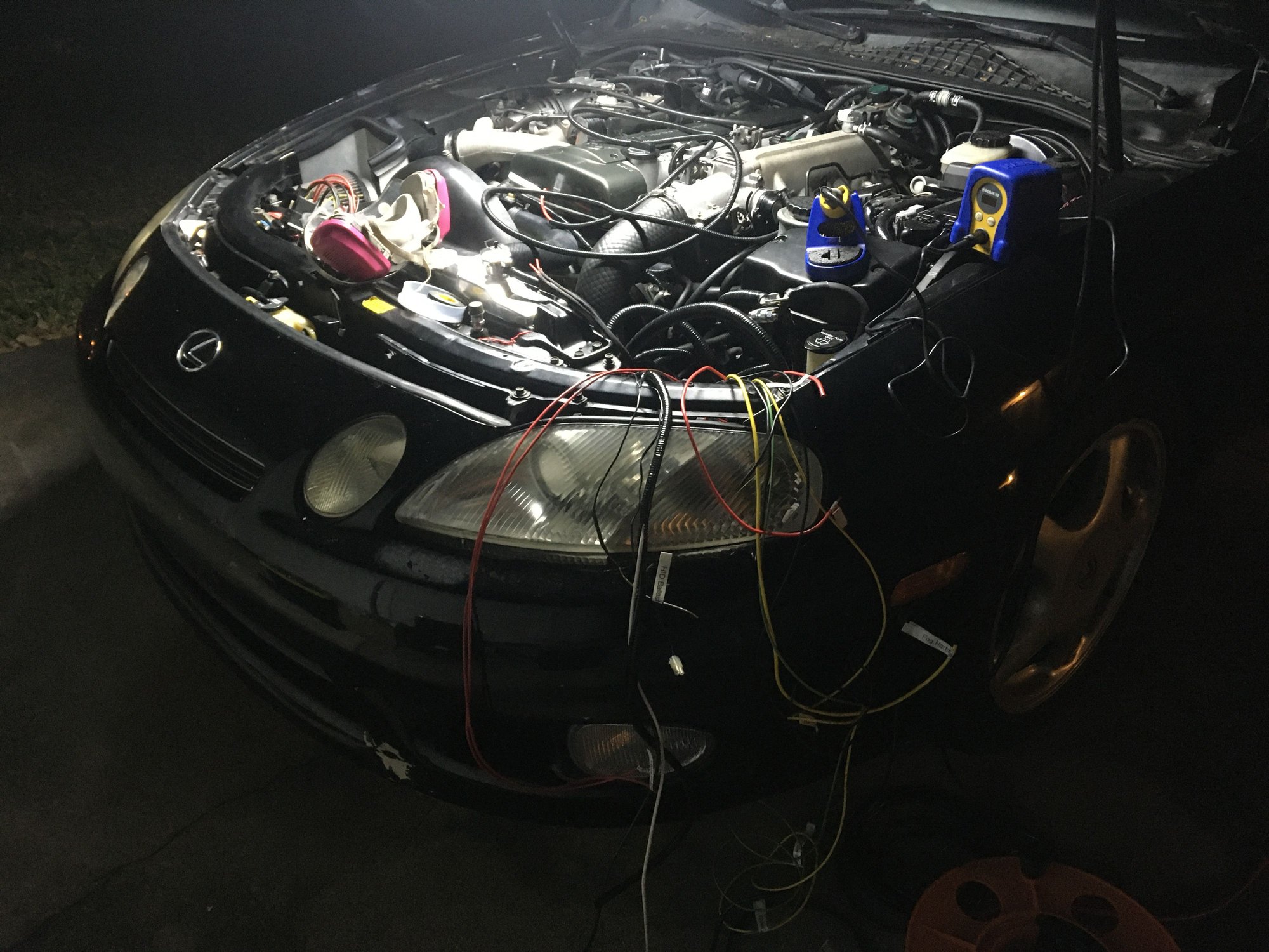
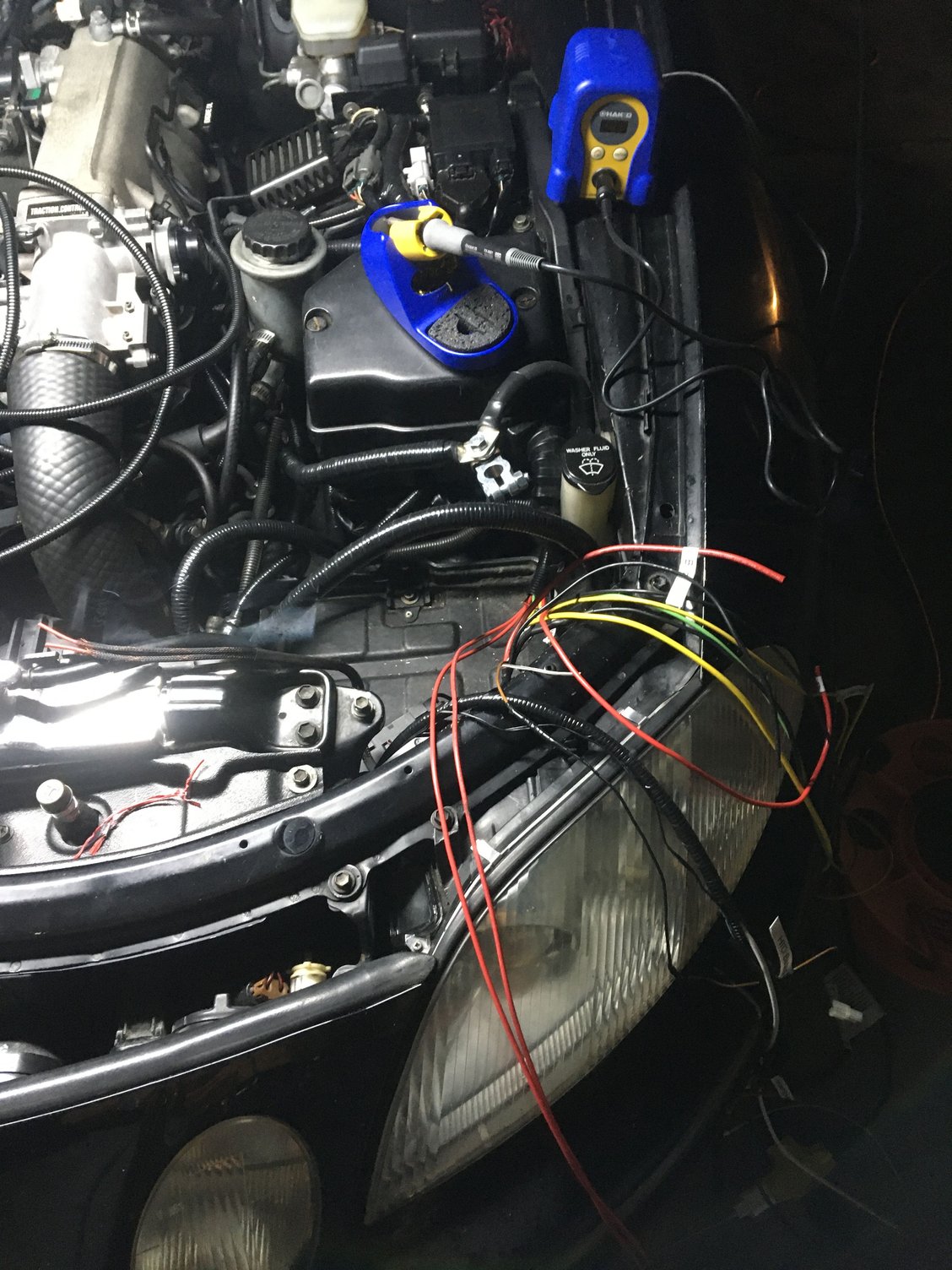
It took me a couple of months to acquire all the new parts I needed, get through each task and slowly and carefully get the electrical accessory, charging and ignition system overhauled.
More on the final result later but unfortunately I found tonight after the SC started up on the first try since November 2nd 2020 that my voltage is still unstable... and it still managed to shut down with another CEL 14 (bad/inconsistent IGF signal error).
I’ve pulled my ECU #3 (which has not yet been capacitor serviced) for inspection. I’ll start into that tomorrow.
Here’s a list of what I’ve done since November when the engine was last fired up until last night (tonight) when I started it up again:
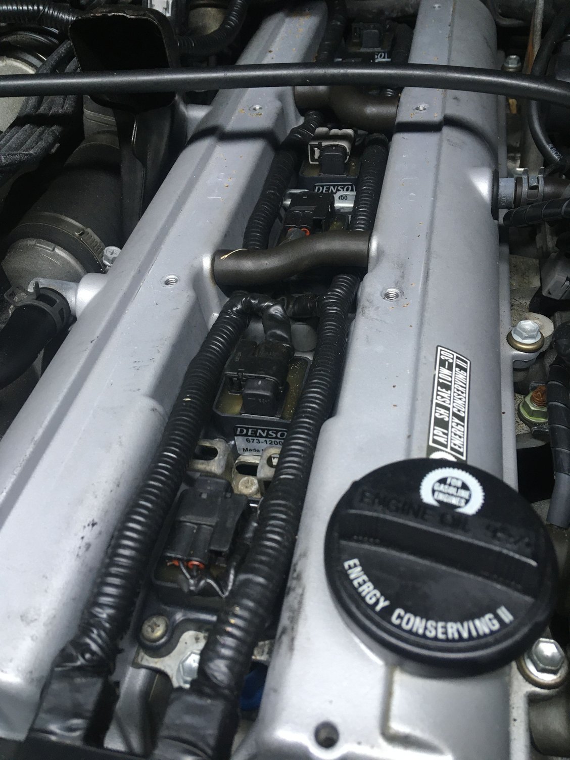
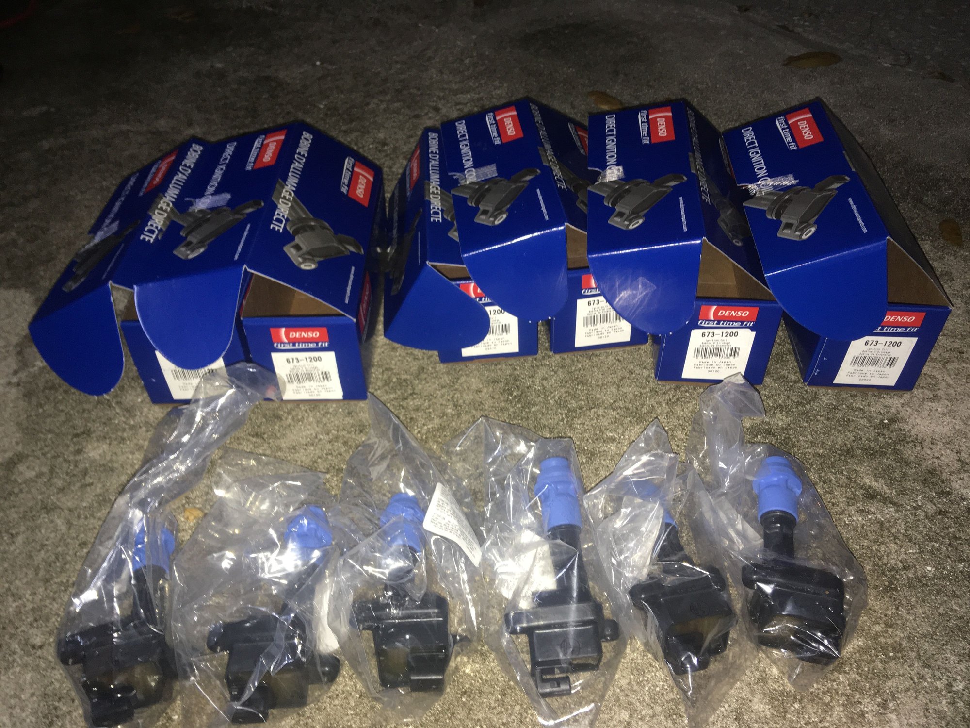
—installed x6 brand new Denso TT coil packs
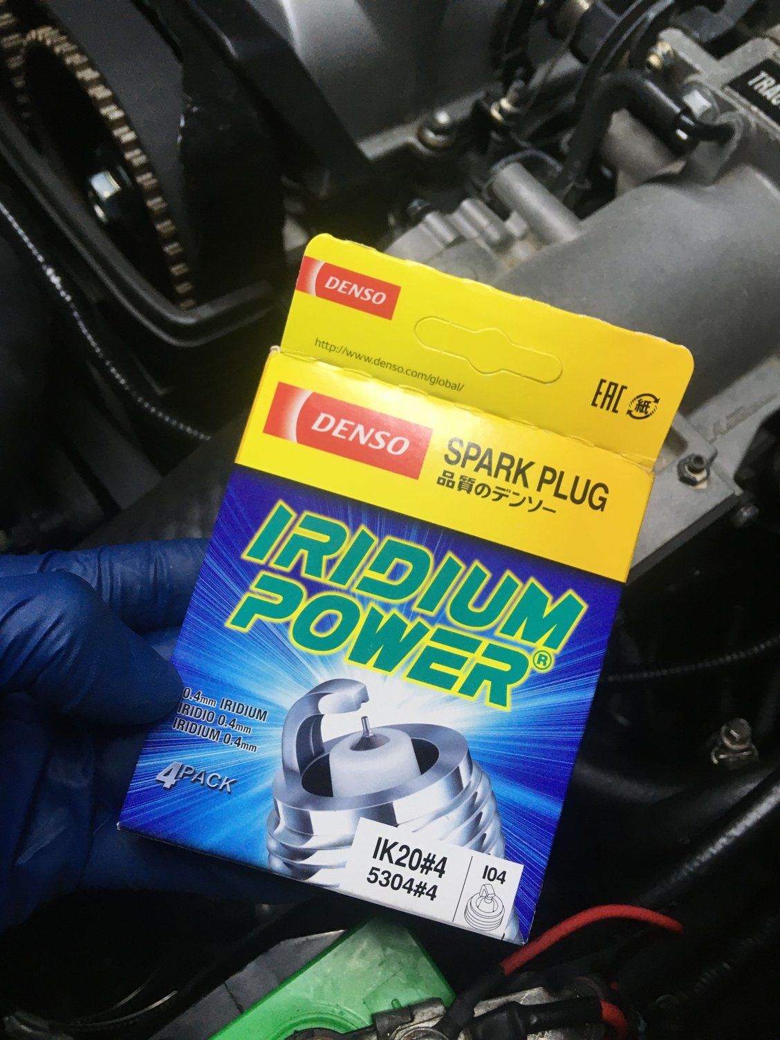
—installed x6 brand new Denso IK20 plugs
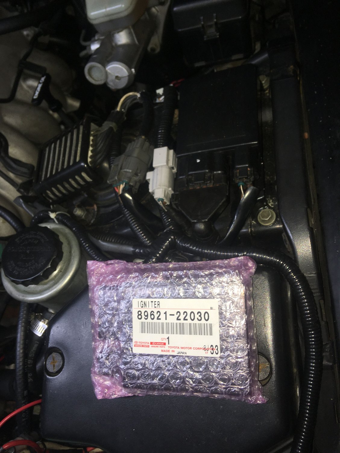
—installed another brand new OEM 1JZ/2JZ igniter from Driftmotion
—repaired slightly frayed old crank sensor wires at connector with new OEM terminals
—sanded down, primed and repainted the OEM battery tie-down part in black with an infused slight urethane to better resist dings and scratches.
—installed a pair of new hood struts
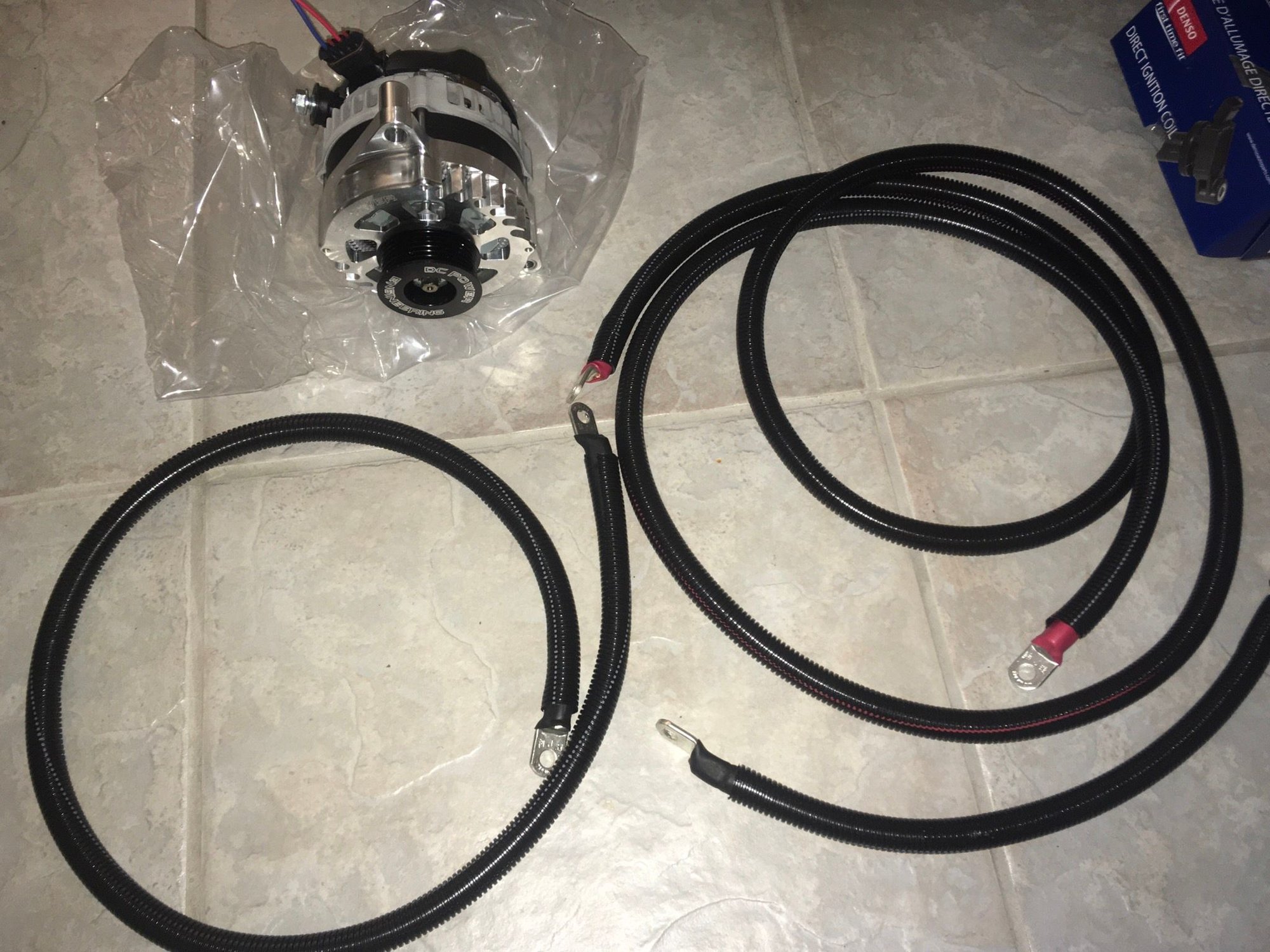
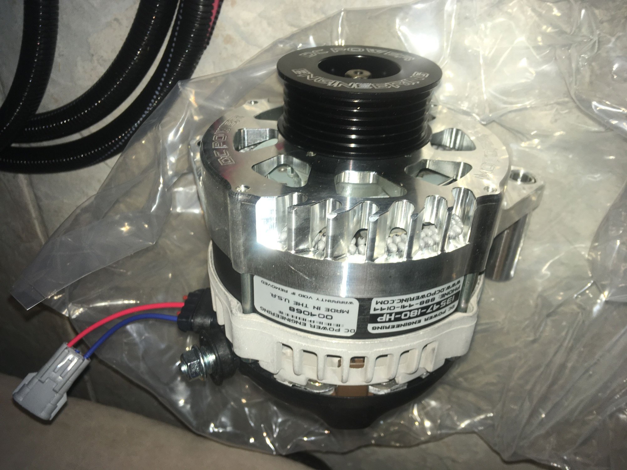
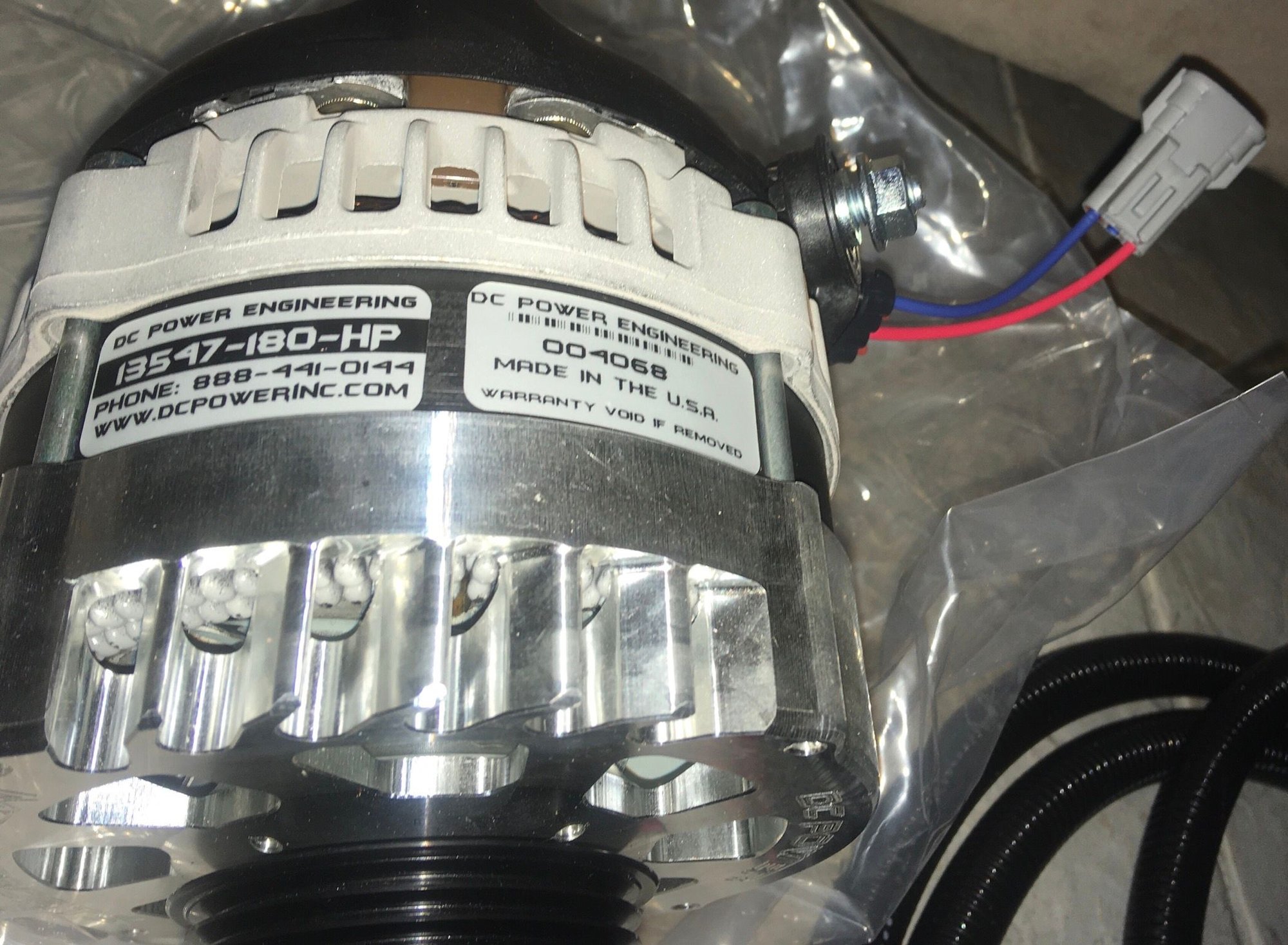
—installed new DC Power 180-amp 6-phase alternator
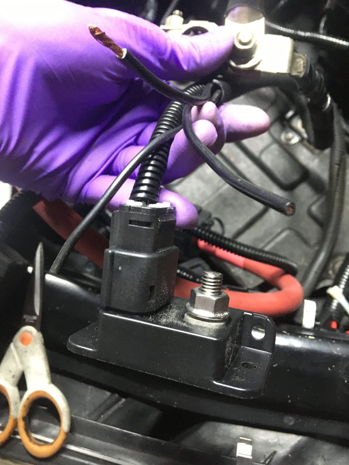
—“Big Three” upgrade with 2/0 cables: additional alternator to batt positive w/200A in-line Littelfuse brand Megafuse, additional engine block to battery negative ground wire, additional battery negative to chassis ground wire
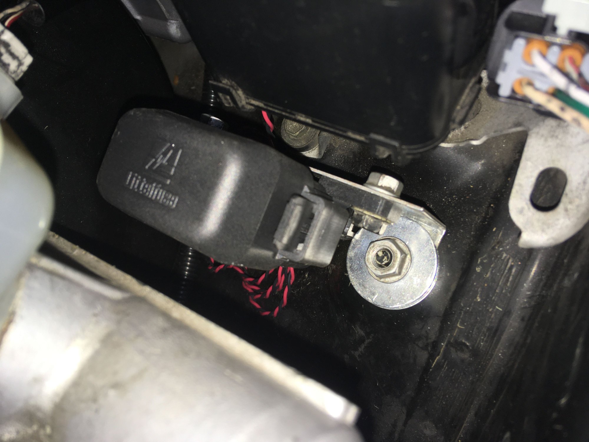
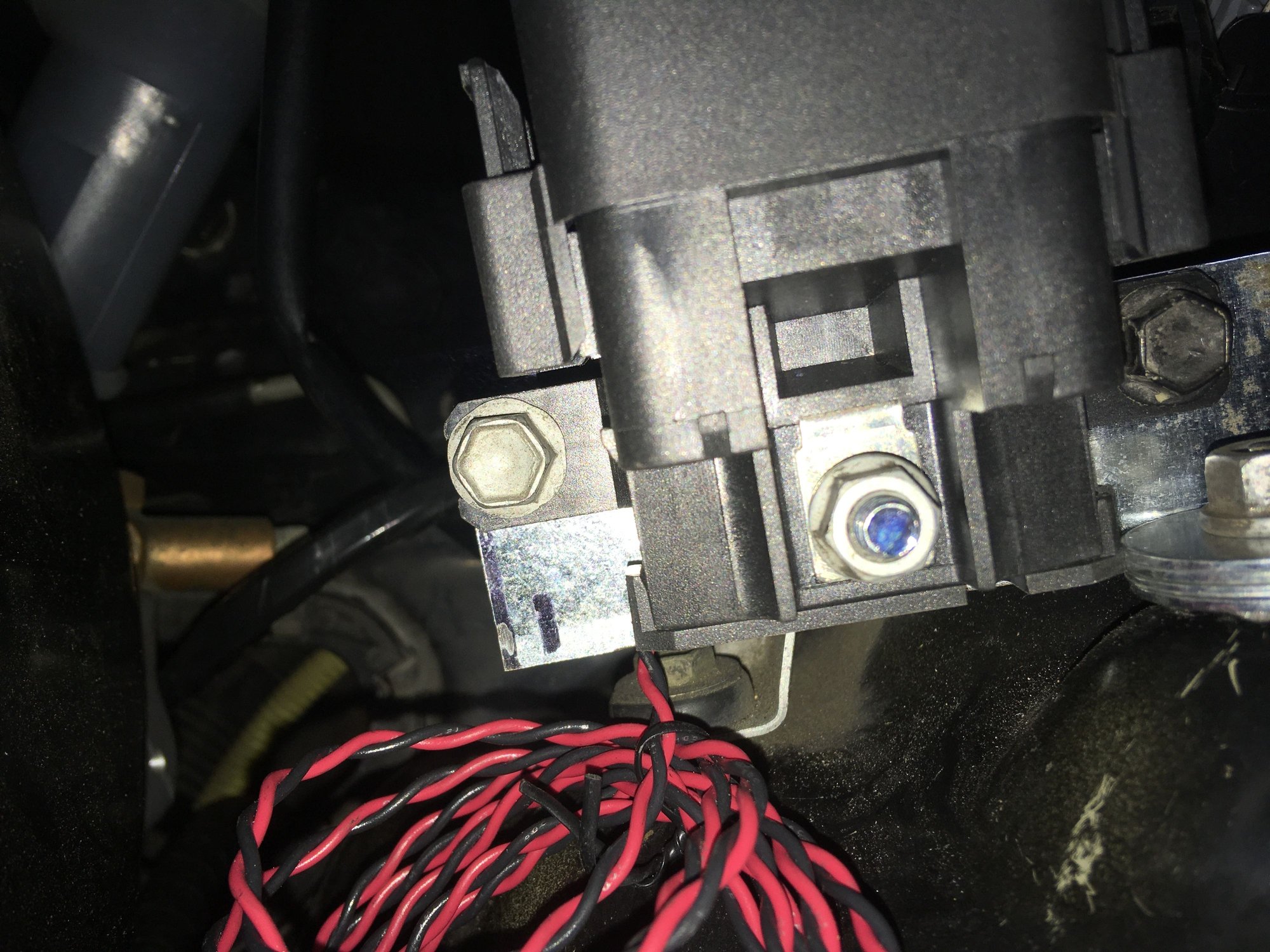
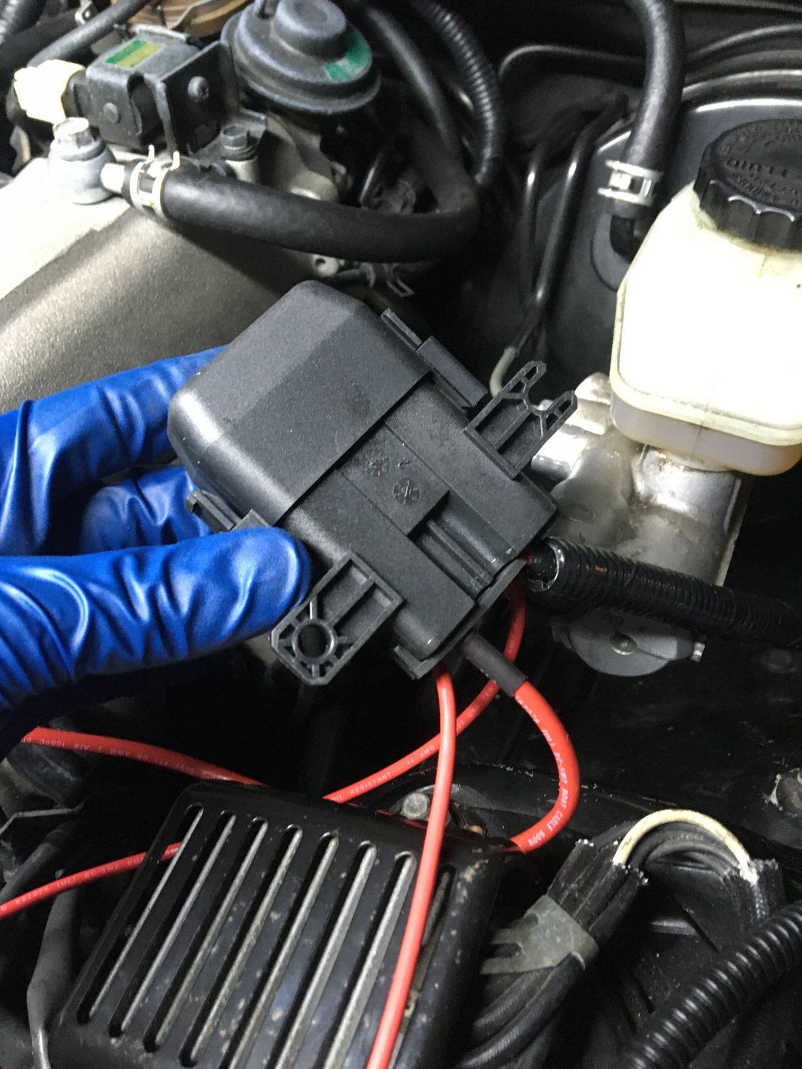
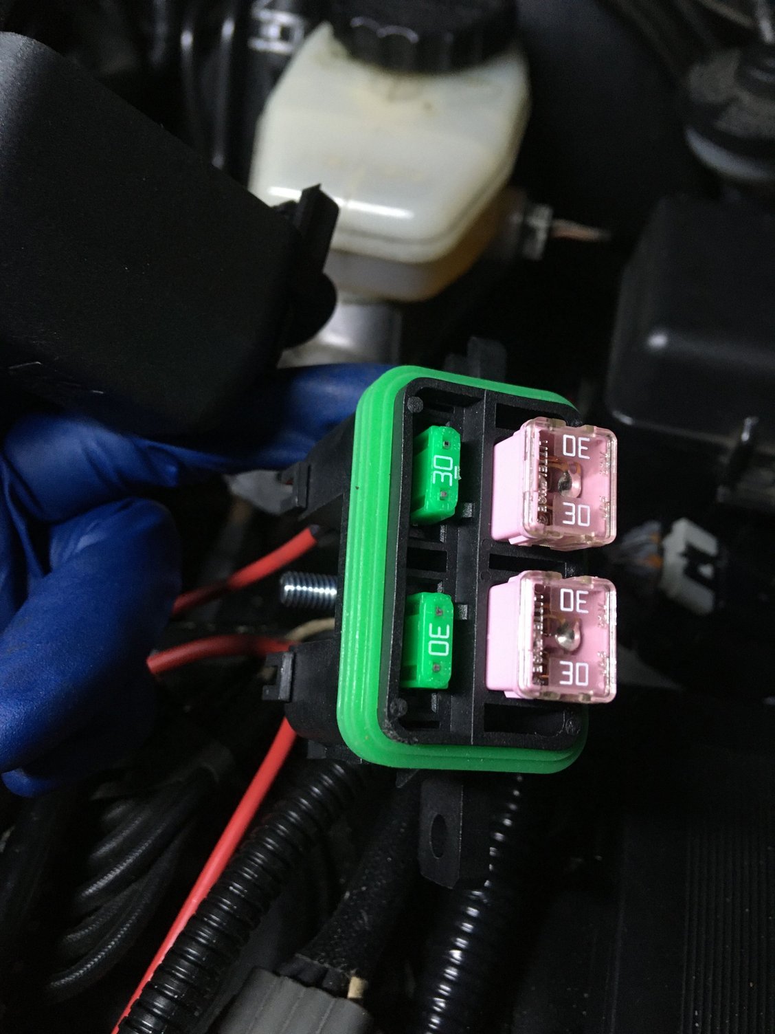
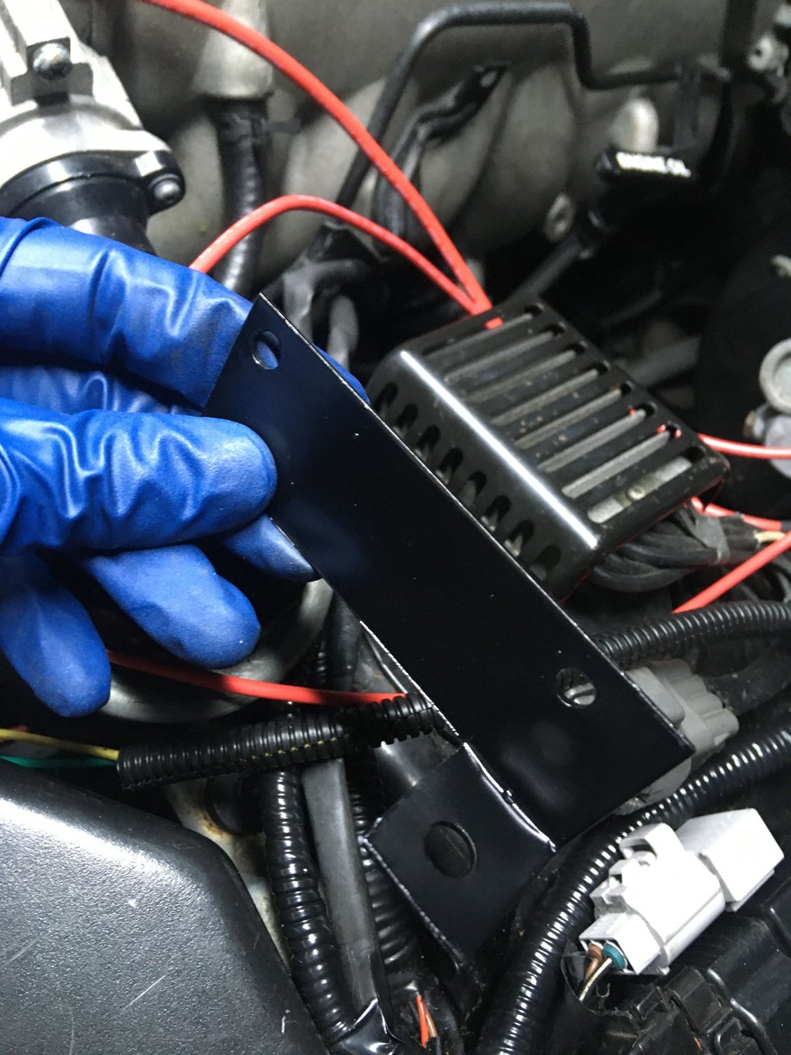
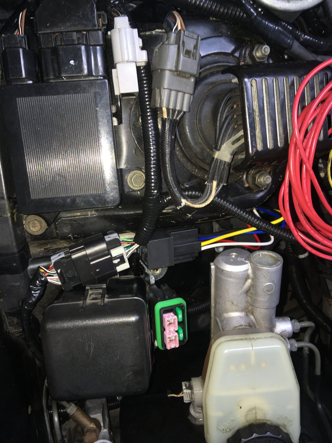
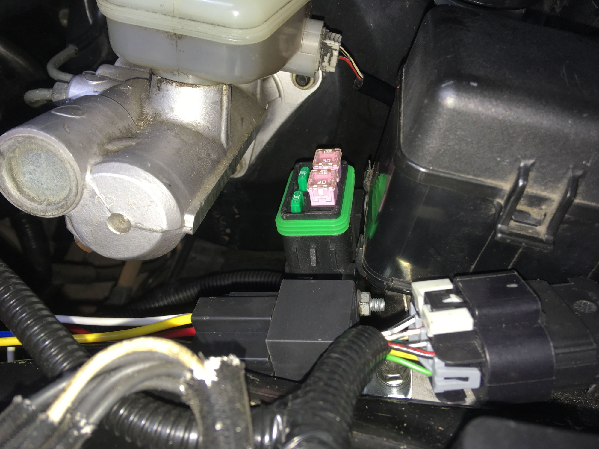
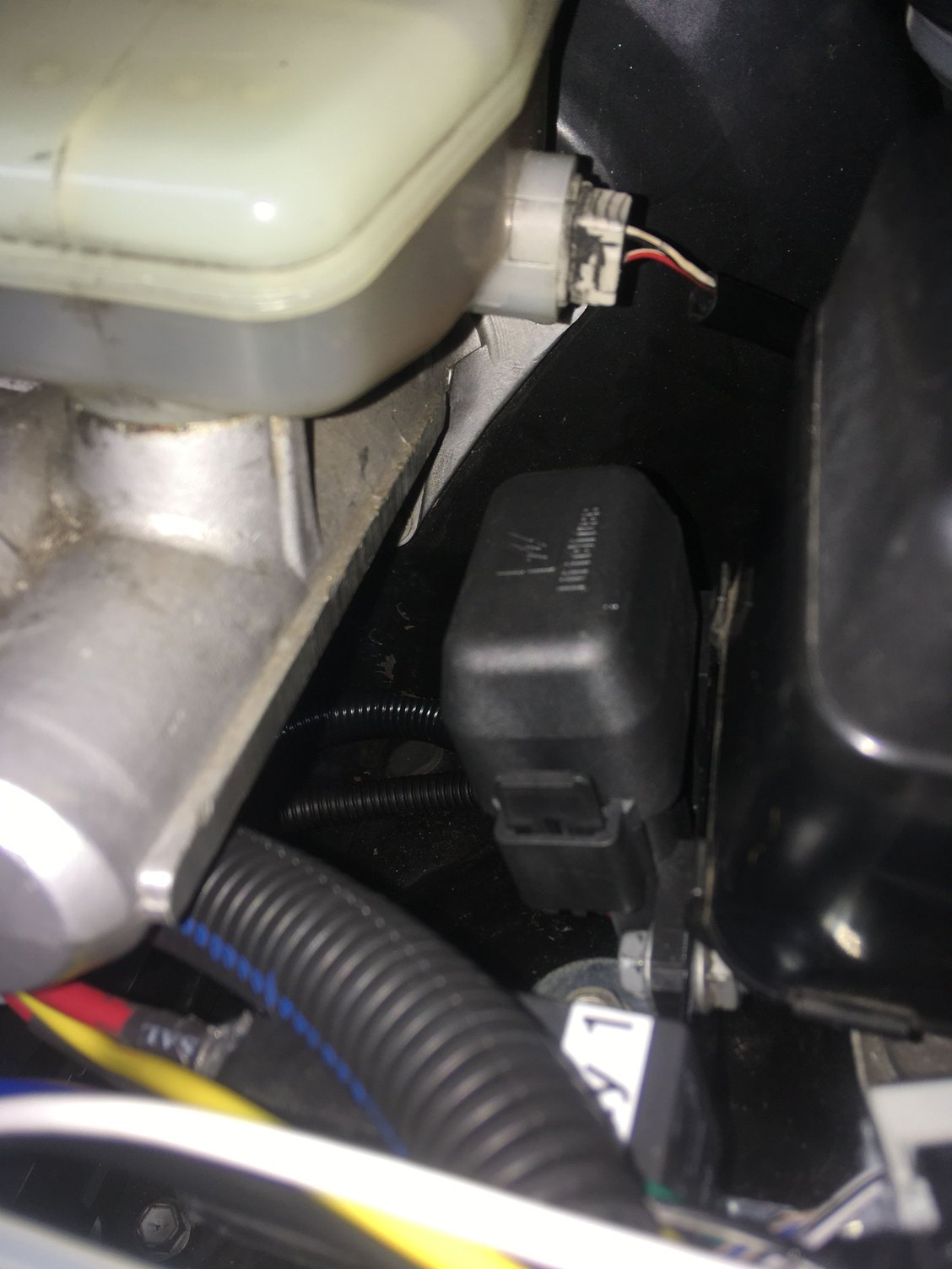
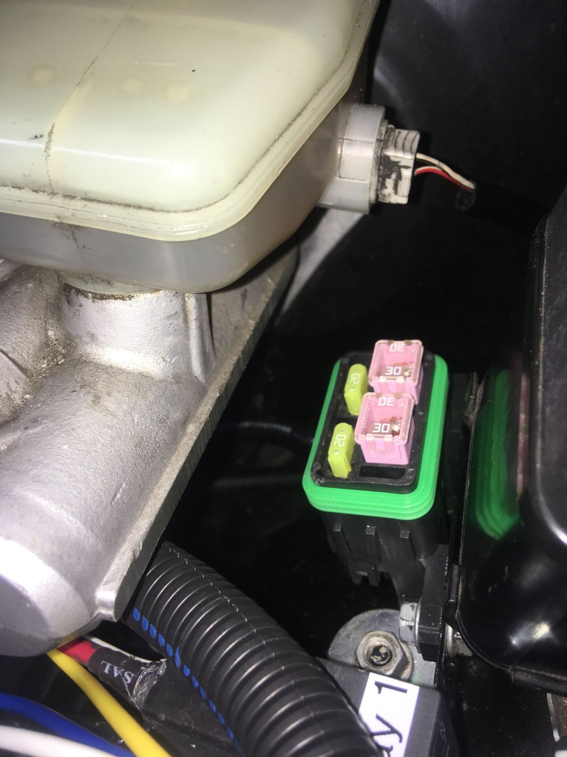
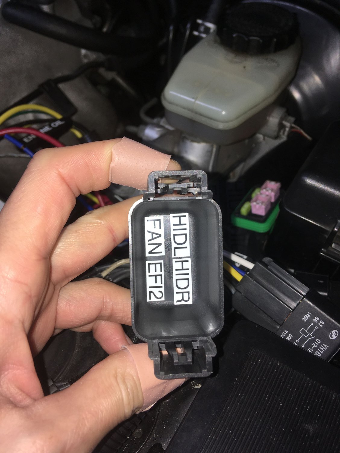
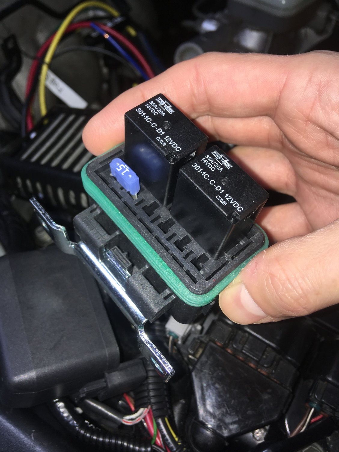
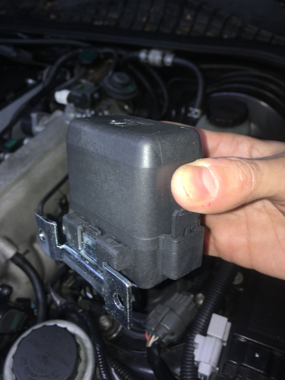
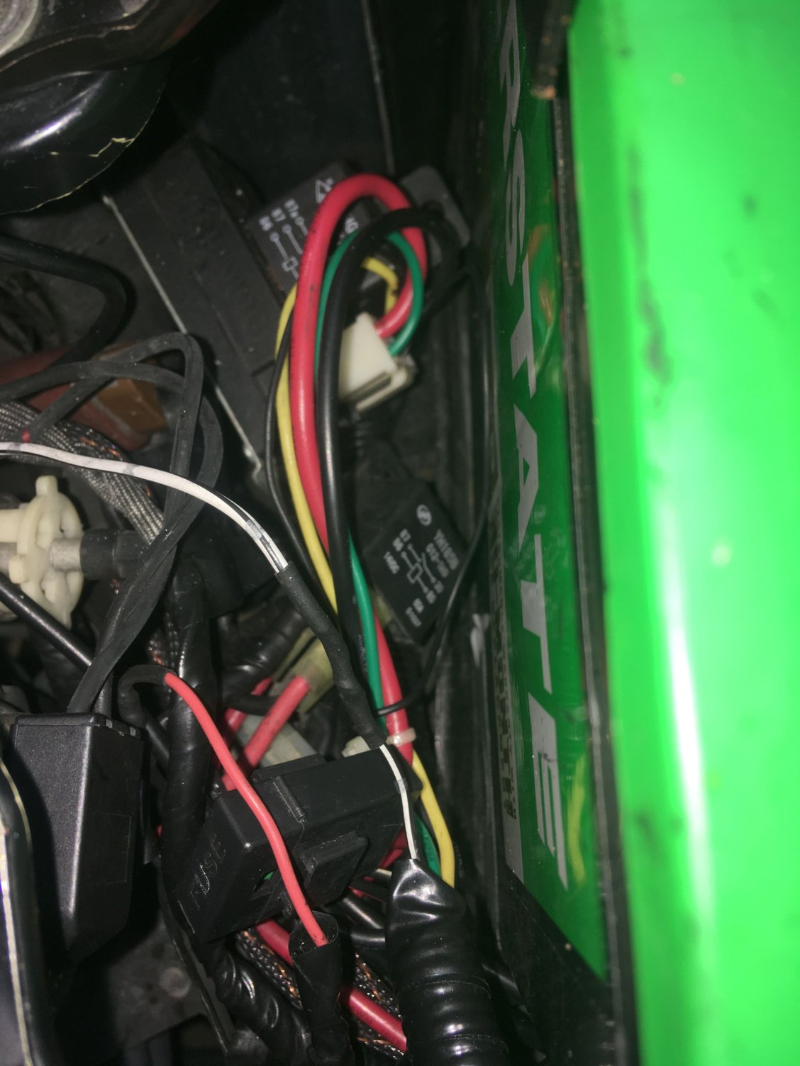
—reworked ALL my old add-on electrical accessory wiring to consolidate extra relays and fuses into small Littelfuse PDMs placed near the brake booster area with custom made brackets and an additional in-line 100A Megafuse for the extra 4GA power feed wire for all of these. All wires and distances calculated, sized, insulated and terminated appropriately.
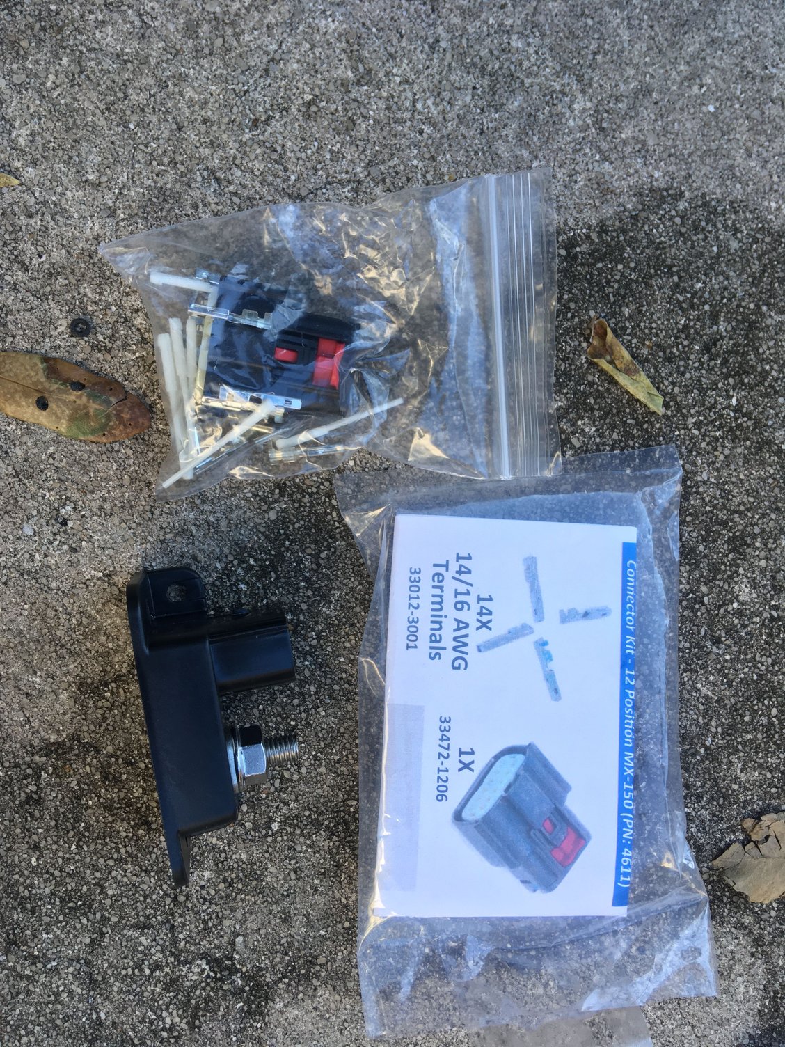
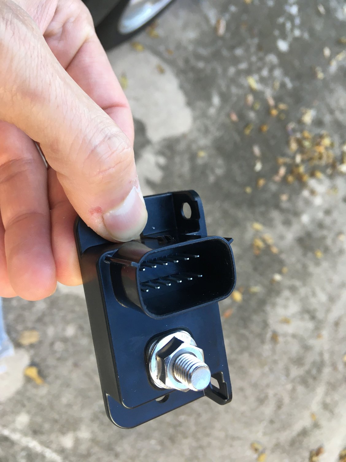
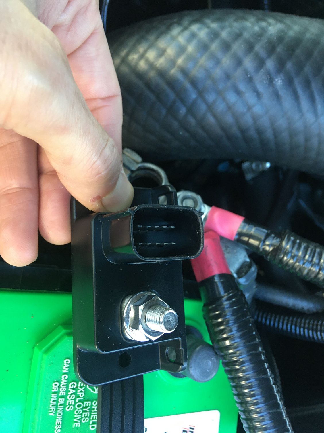
—Added a super compact 200A rated extra accessory ground fuse consolidation unit going into a 4GA wire to a factory chassis ground point.
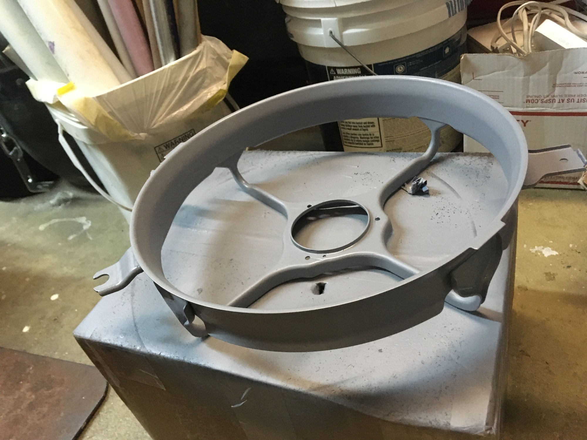
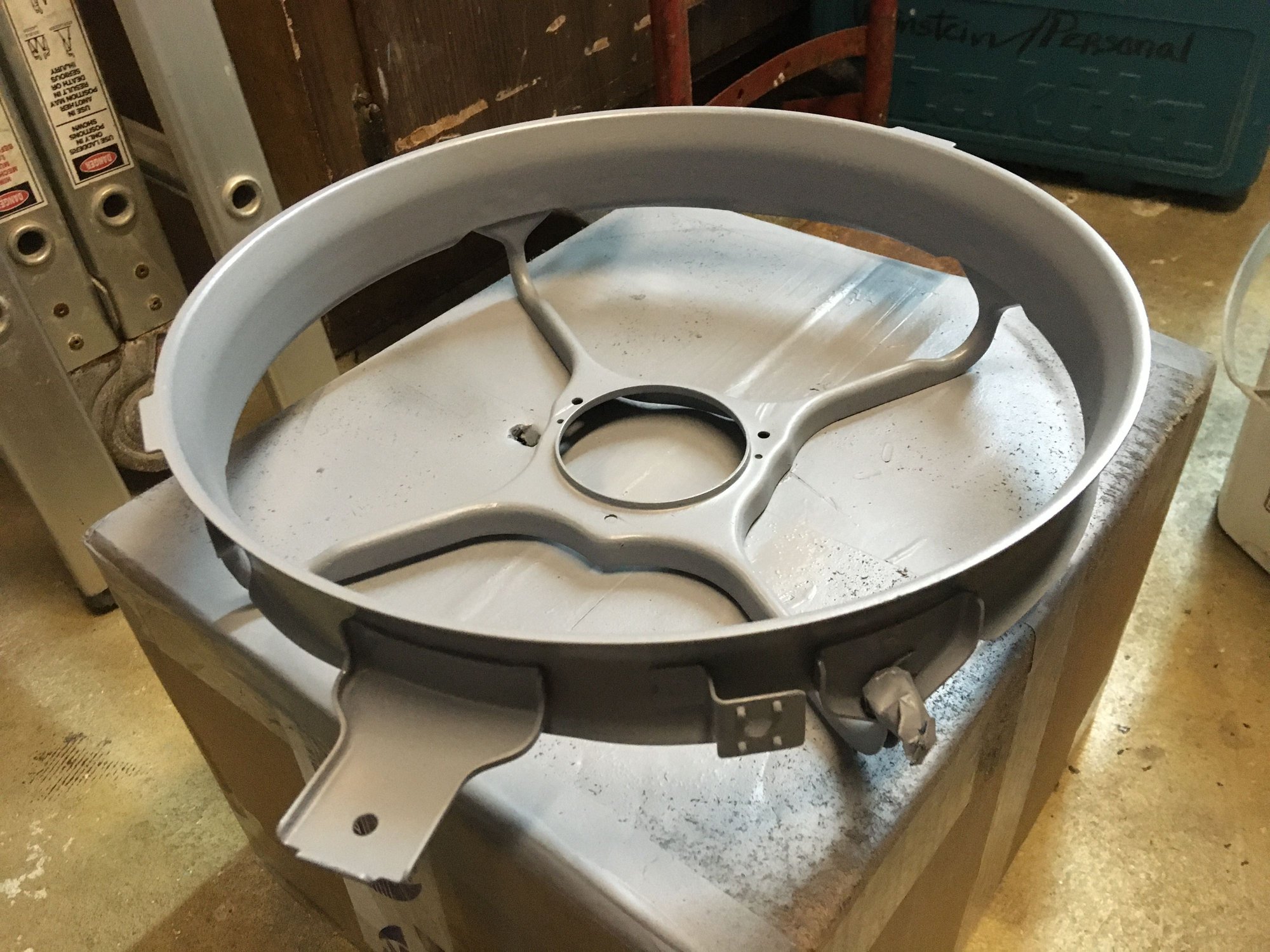
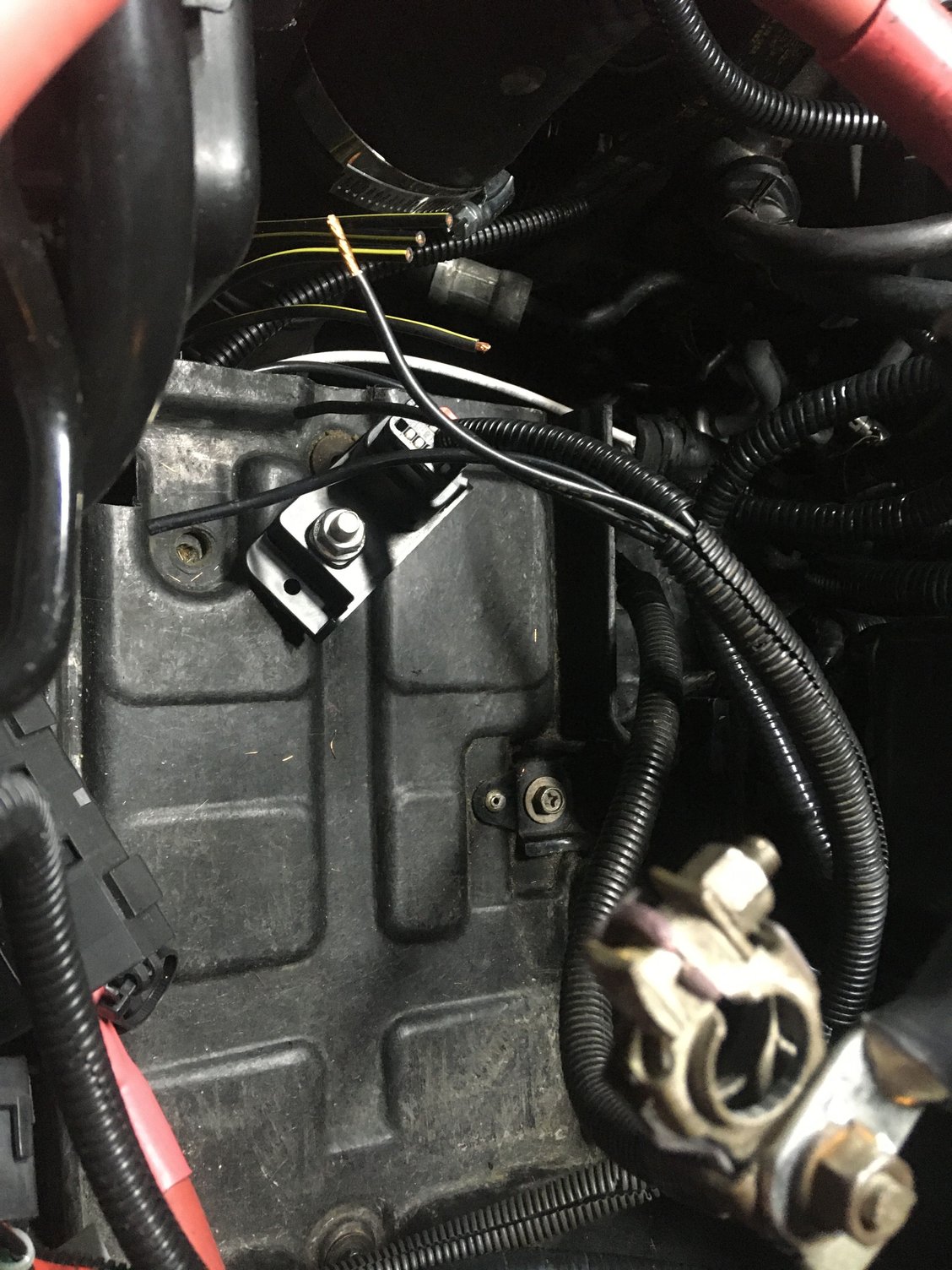
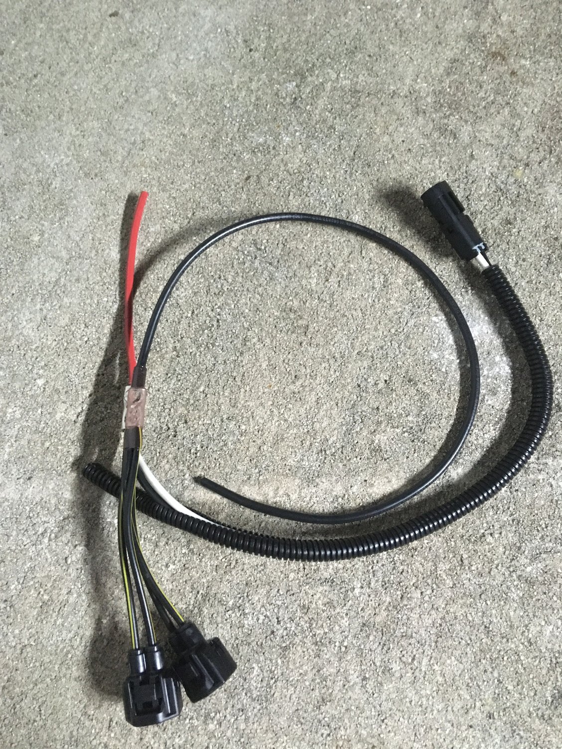
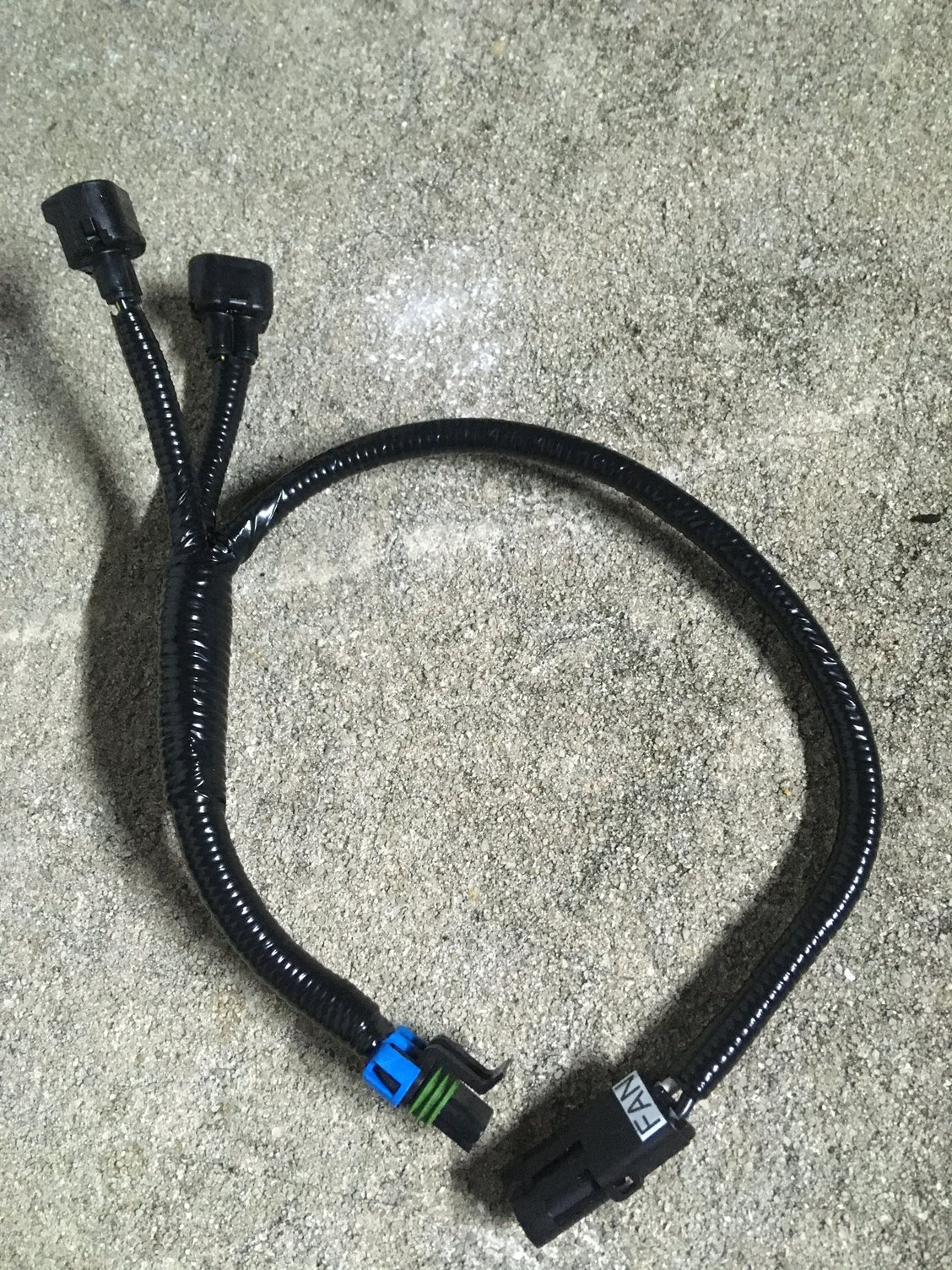
—upgraded from a single aux fan 93-96 Supra TT fan shroud to the 97-98 Supra TT fan shroud:
Now I have the main TT mechanical fan plus two OEM TT aux fans behind the radiator
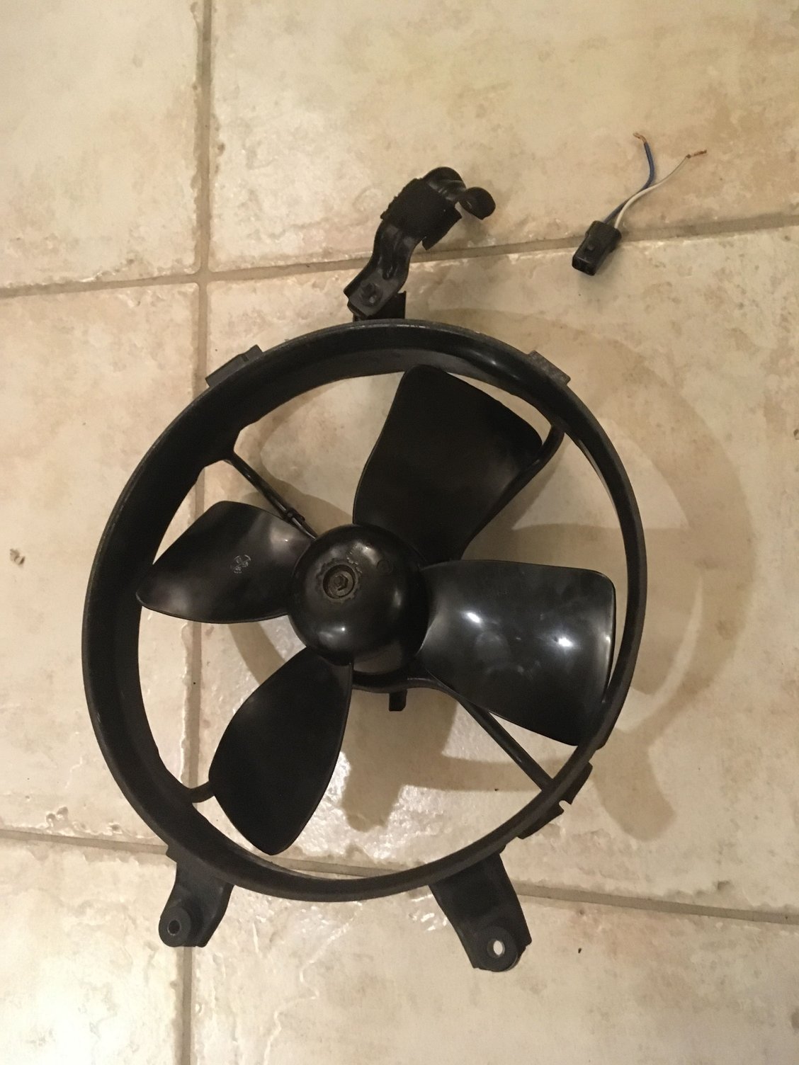
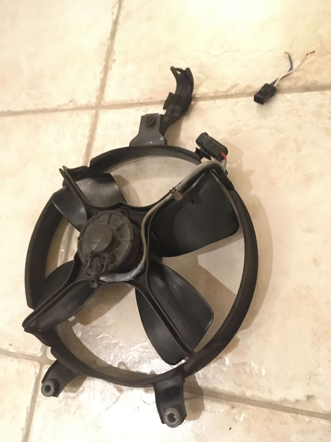
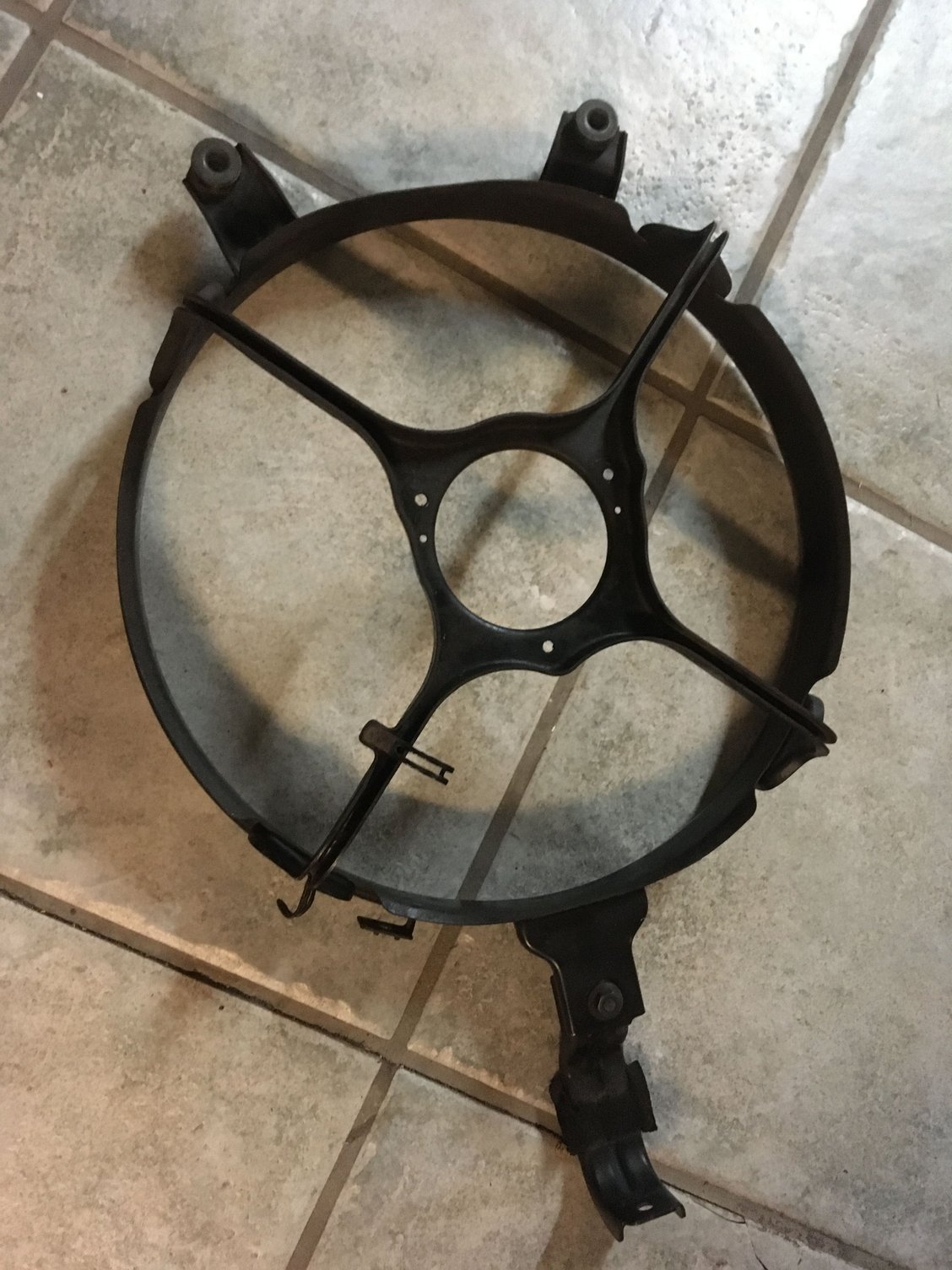
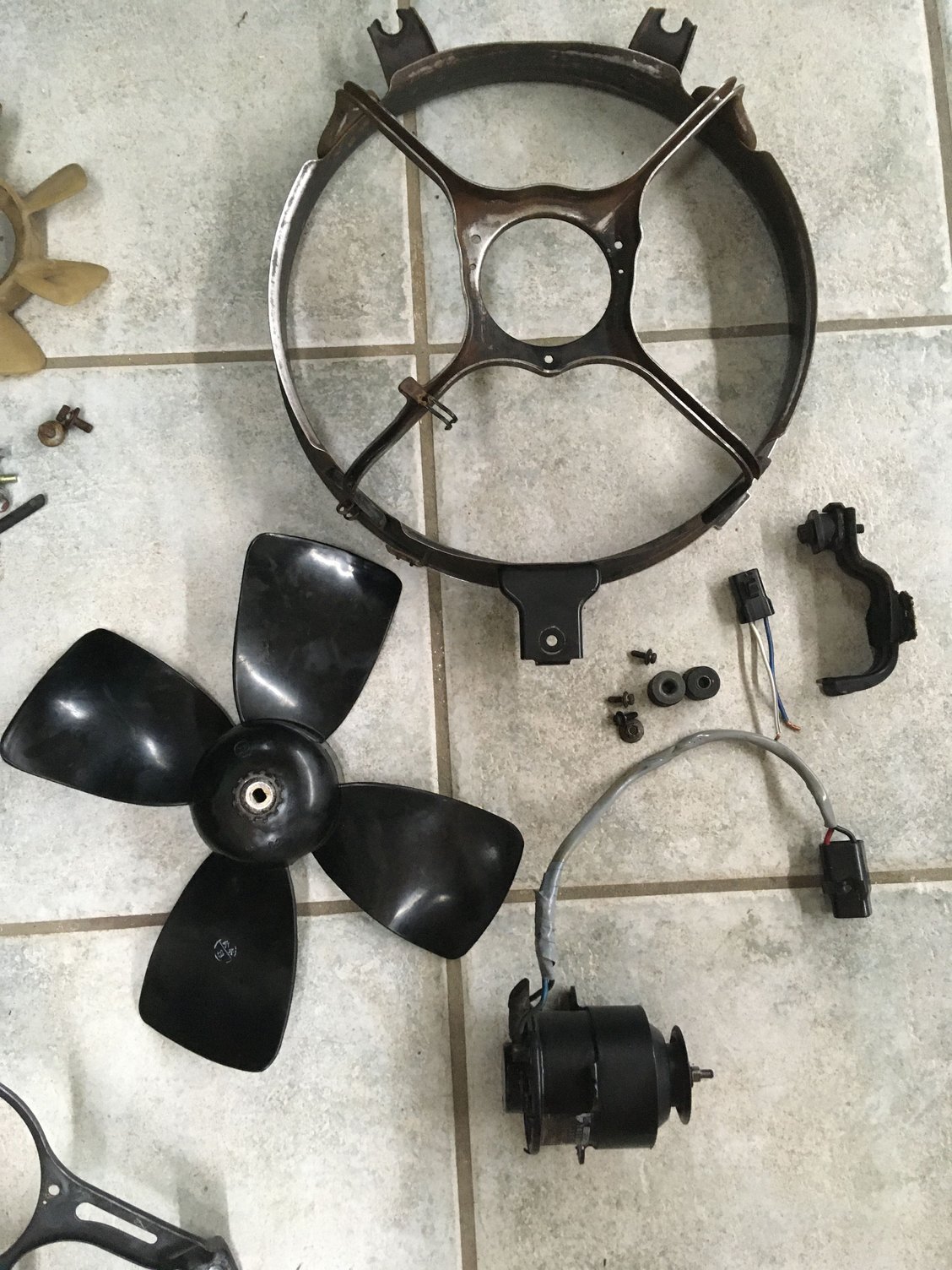
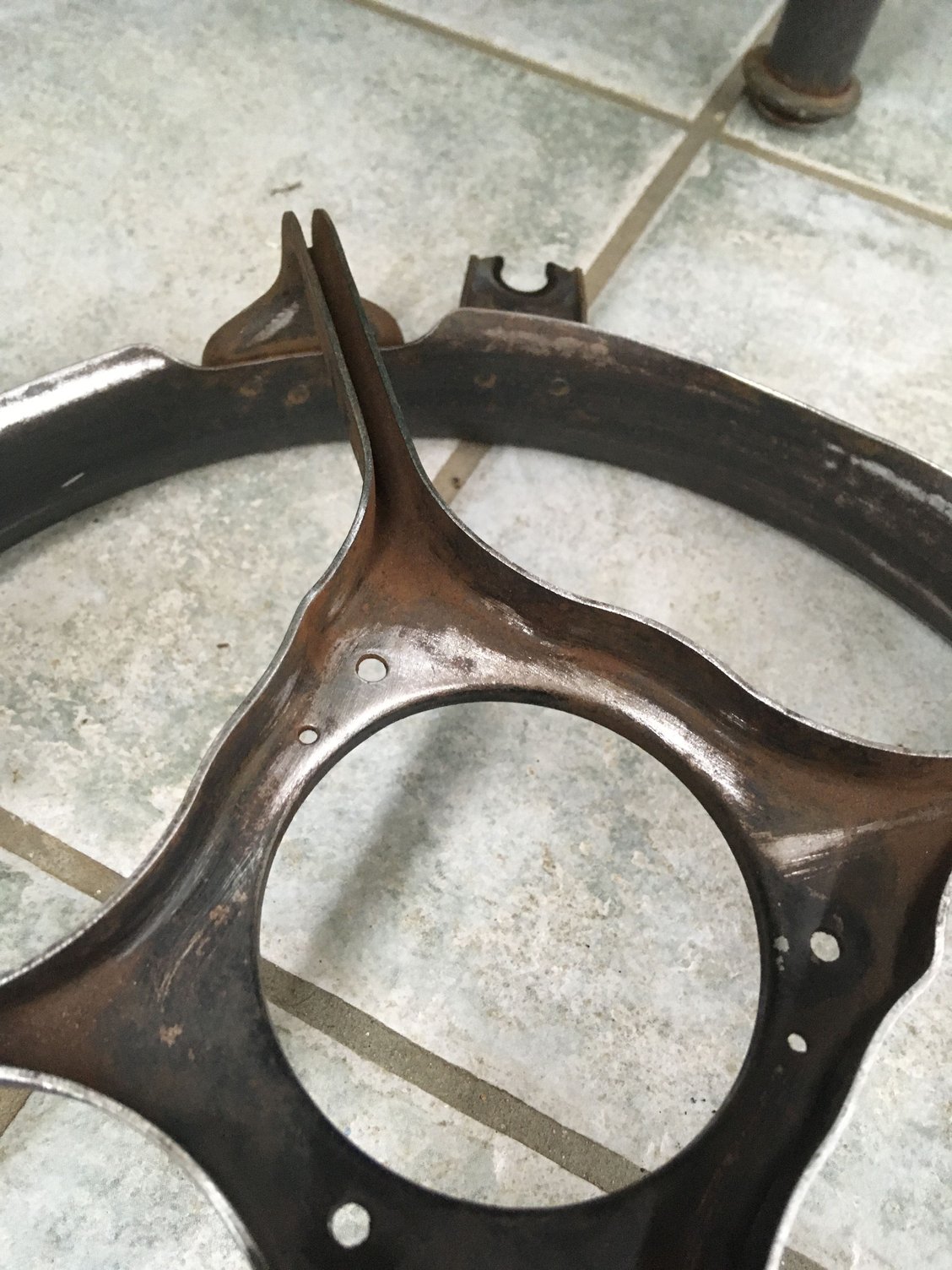
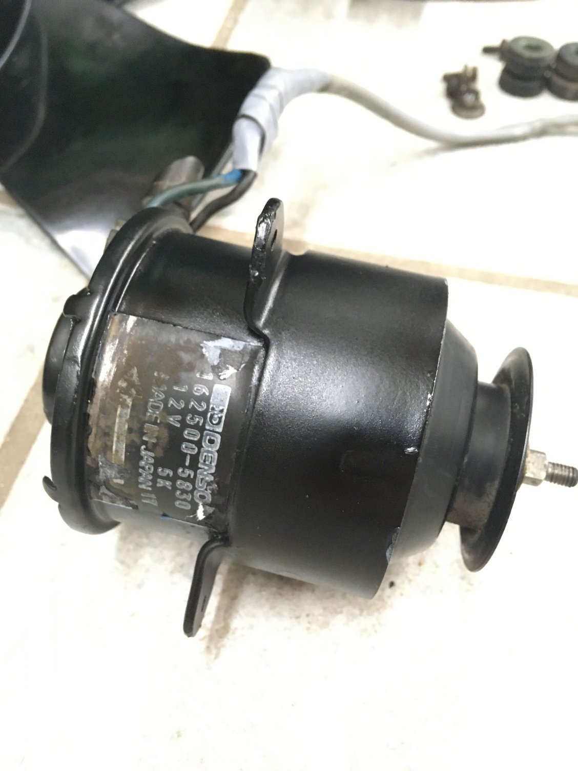
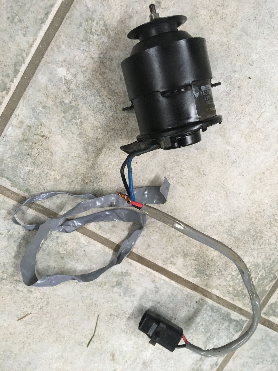
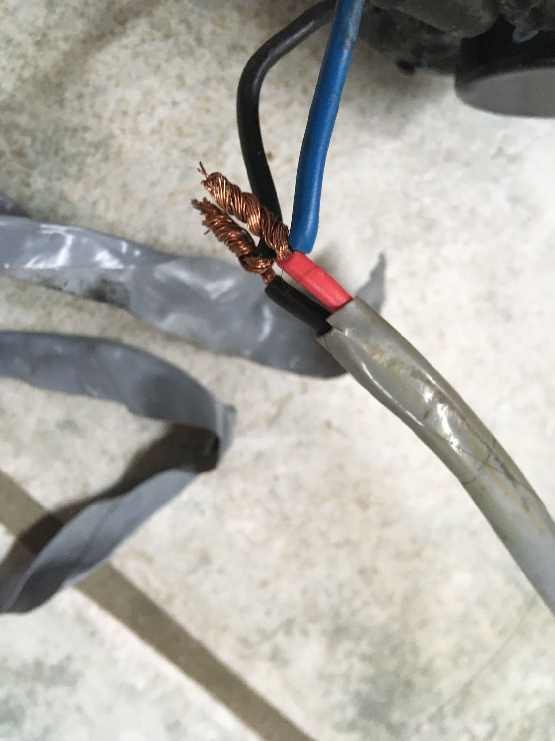
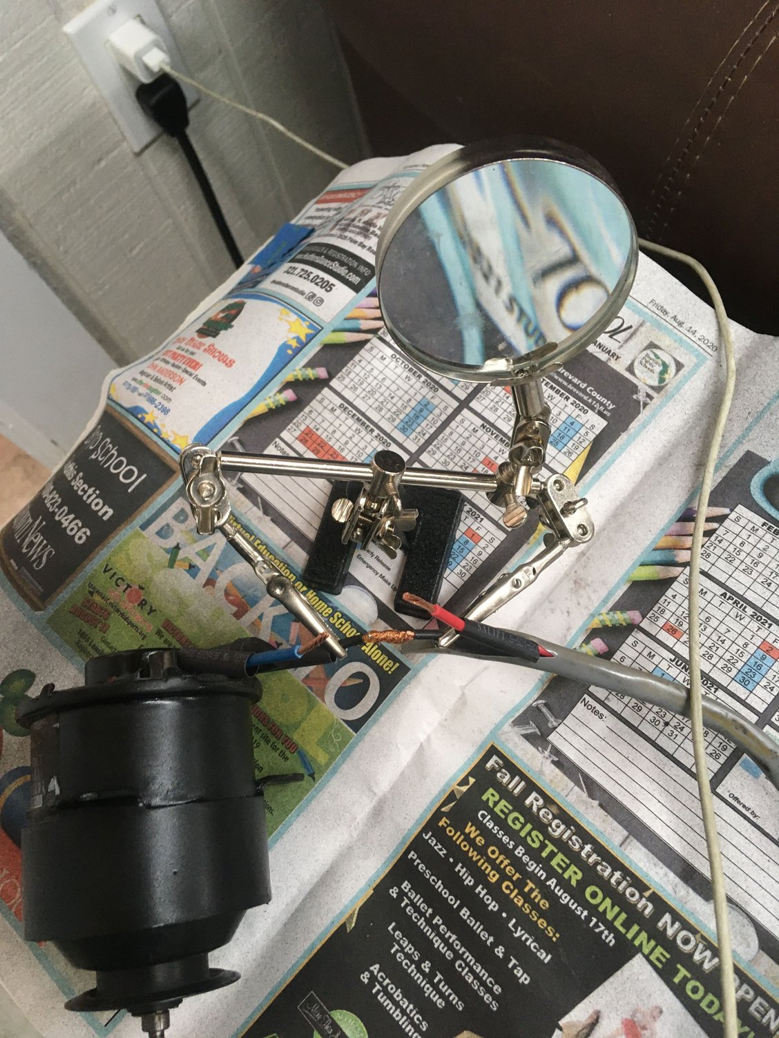
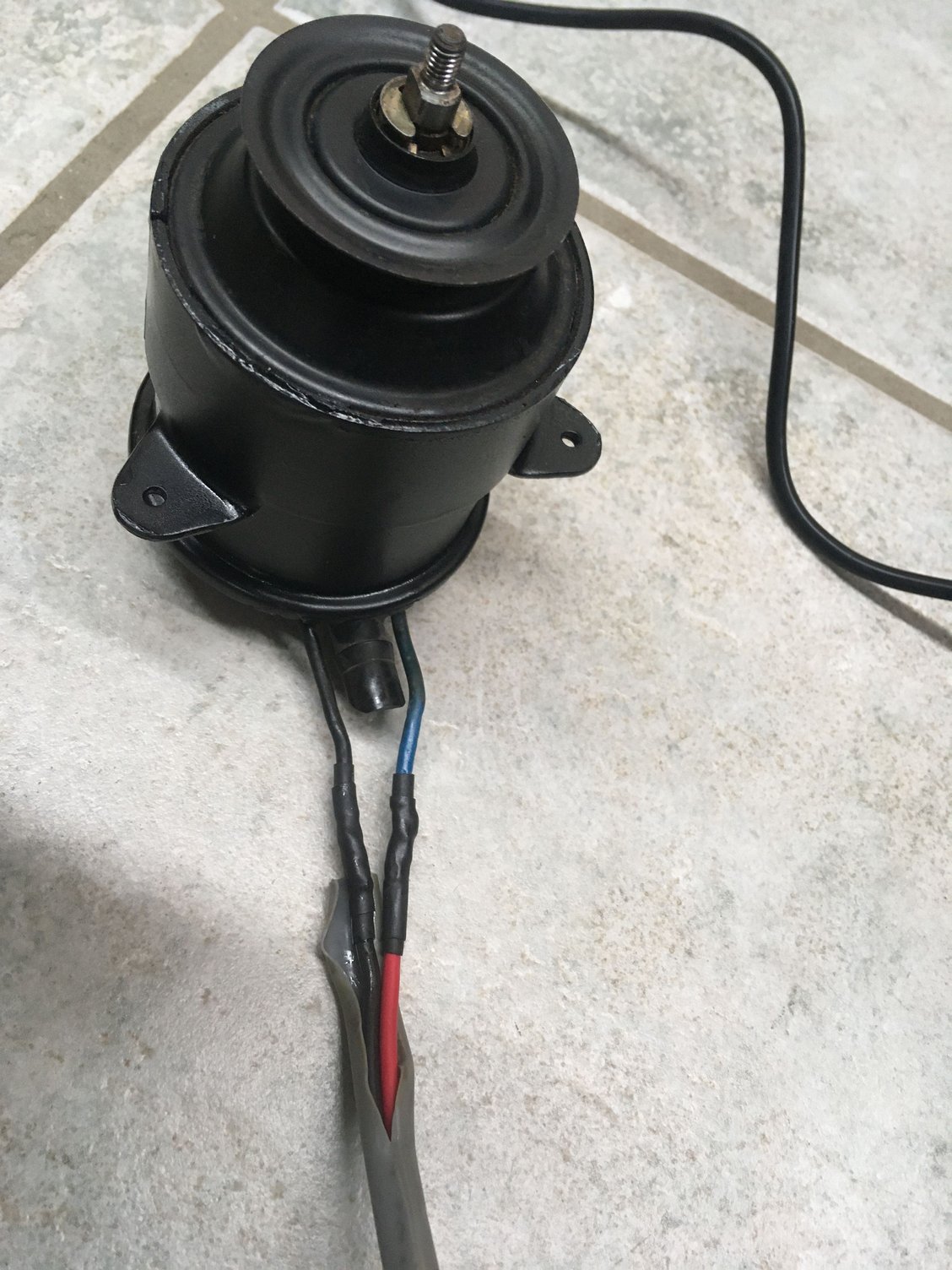
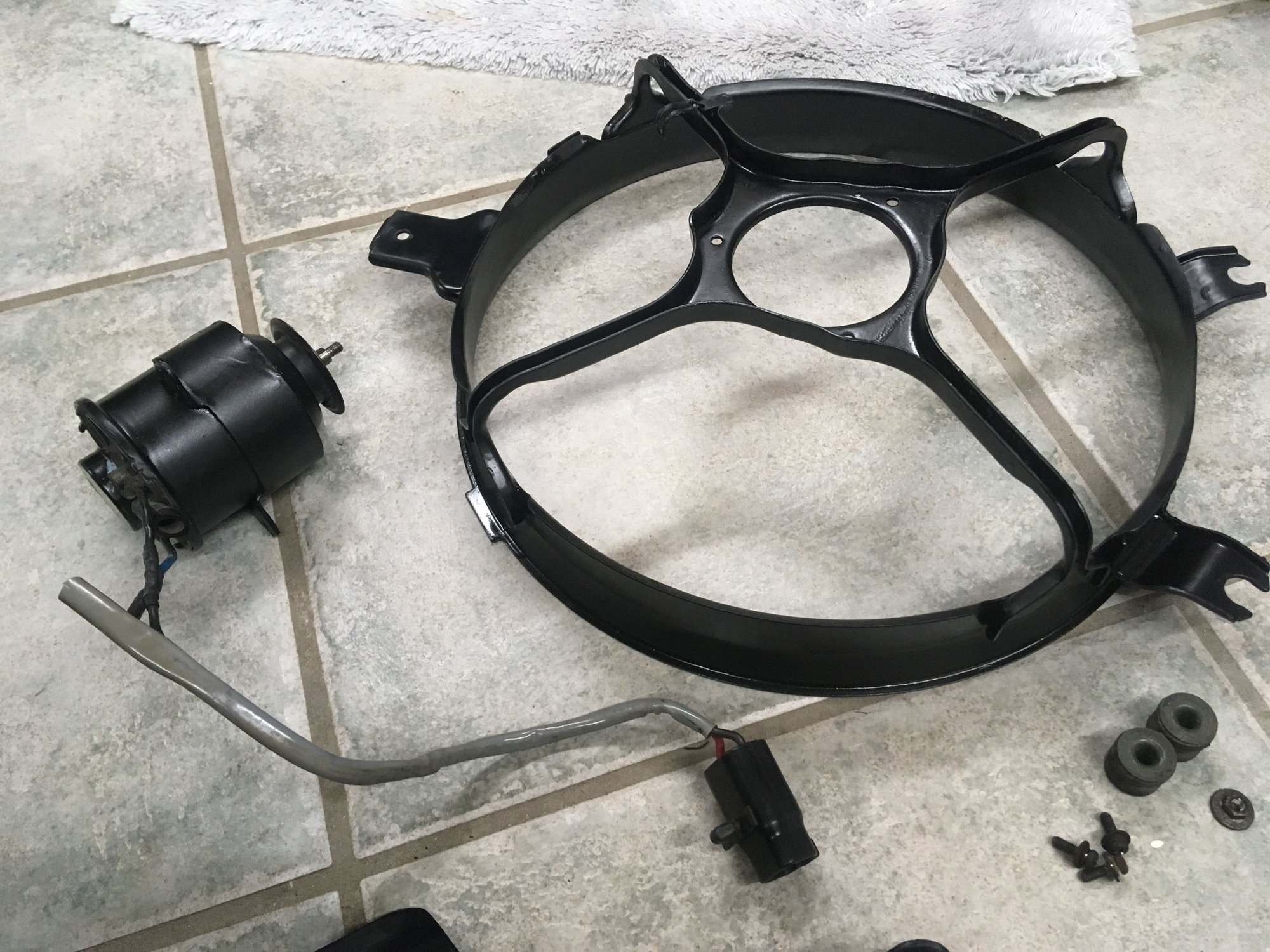
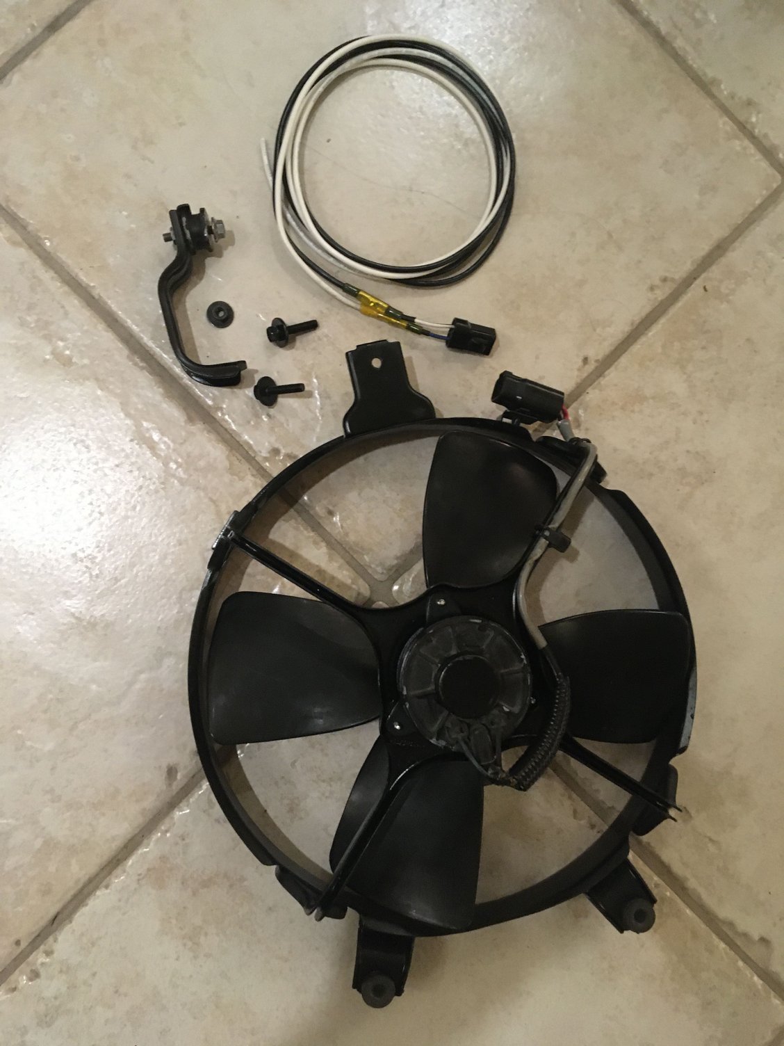
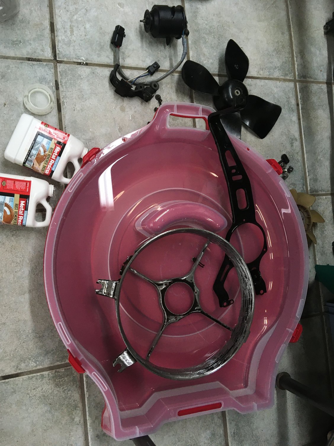
—Found, bought, sanded down, rust repaired, primed, painted and rewired a Toyota Soarer 2.5GT (1JZ-GTE) Automatic model factory A/C condenser fan, bolted it right into the SC and wired it up into the rest of the electric helper fan circuit just like a factory Auto Soarer 1JZ or factory Auto Supra TT.
—Cleaned up and re-located the Mishimoto electric fan controller and better replicated the Supra MKIV TT’s 30A electric fan circuit with the addition of a relay just to keep battery positive feed wire power to the fans limited to engine accessory on mode and ignition on modes only (the Mishimoto controller works as a ground-switching unit).
Pictures of all the work in the next post.
Last edited by KahnBB6; 01-20-21 at 12:24 AM.
#969
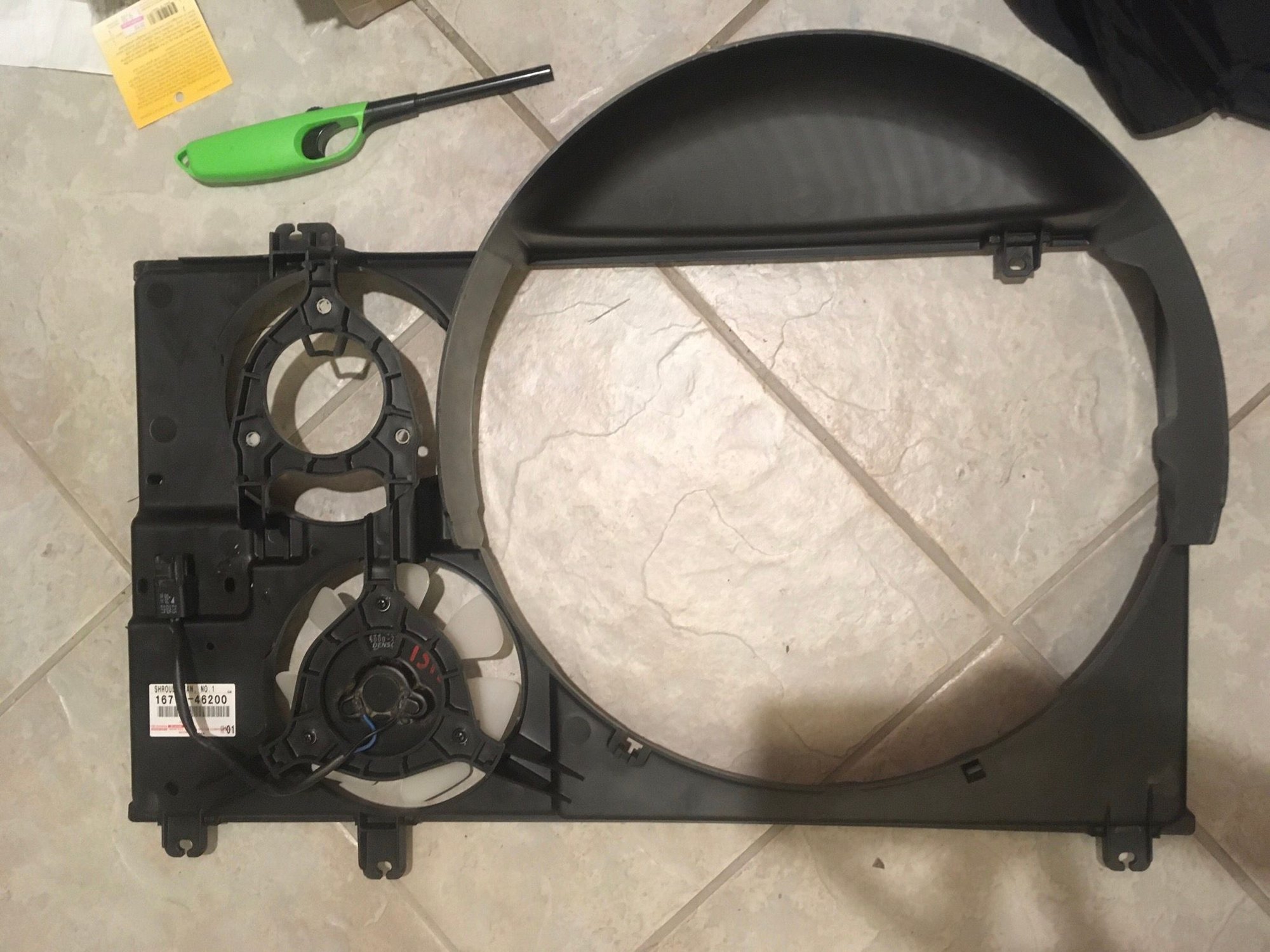
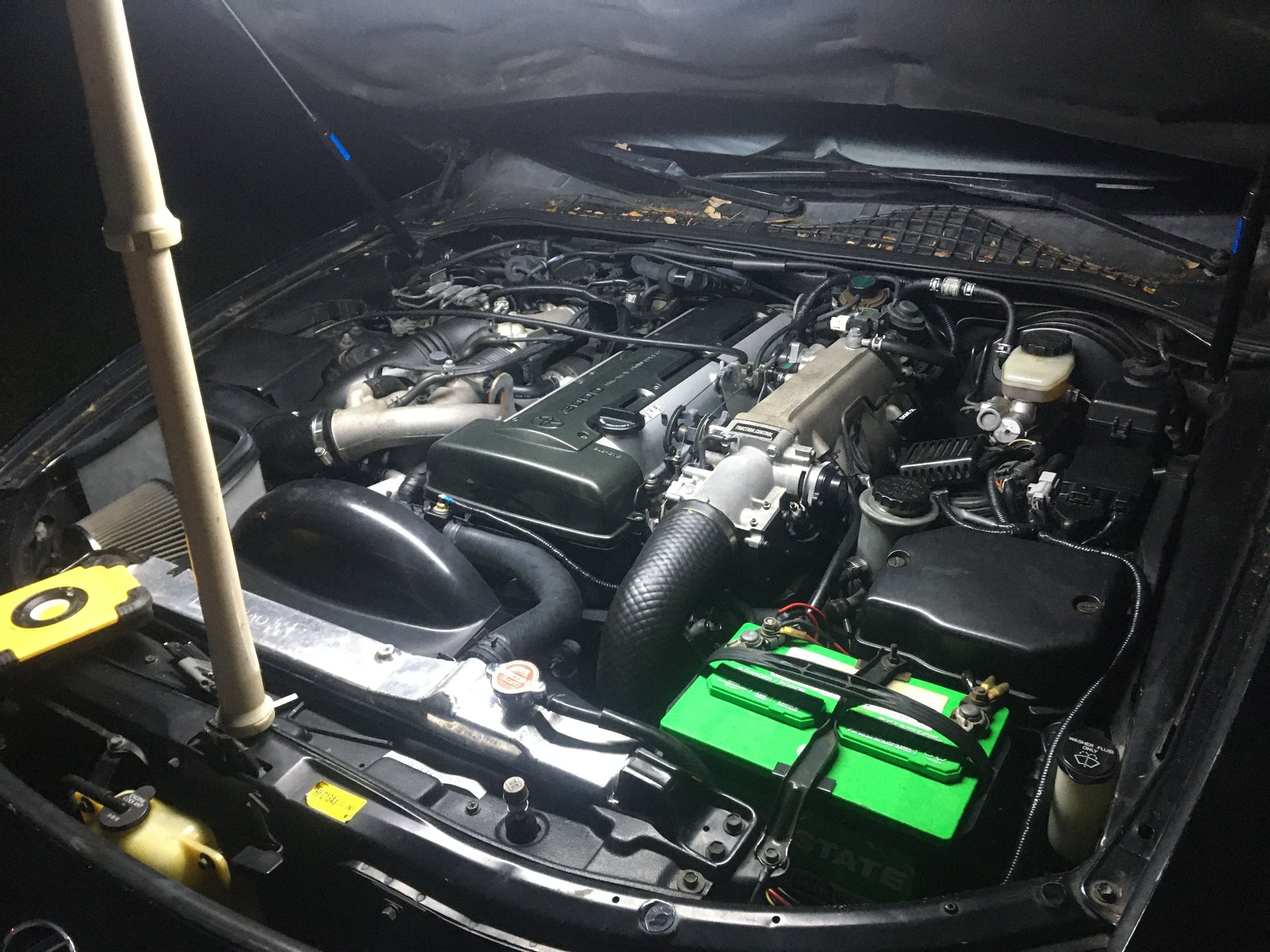
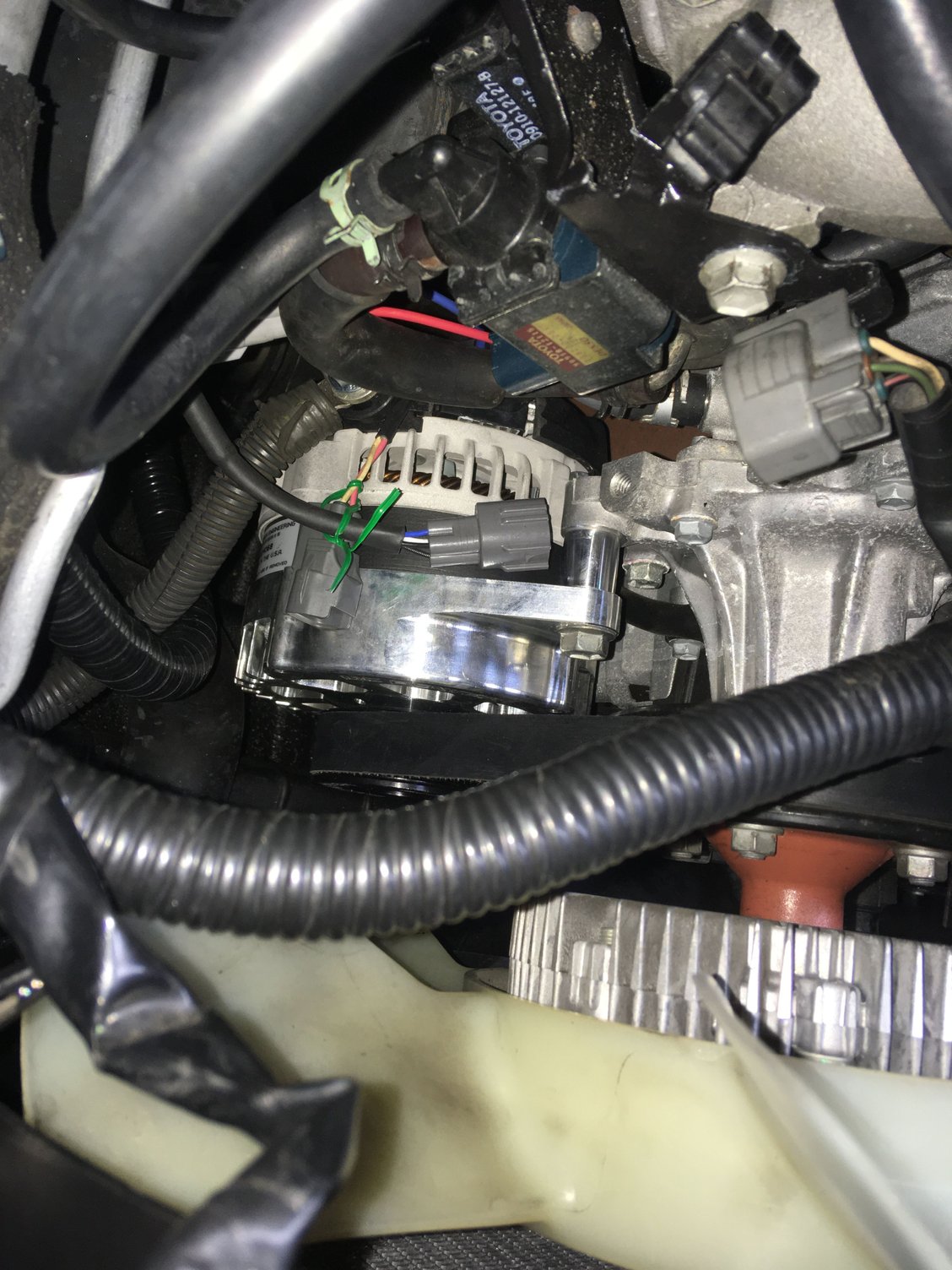
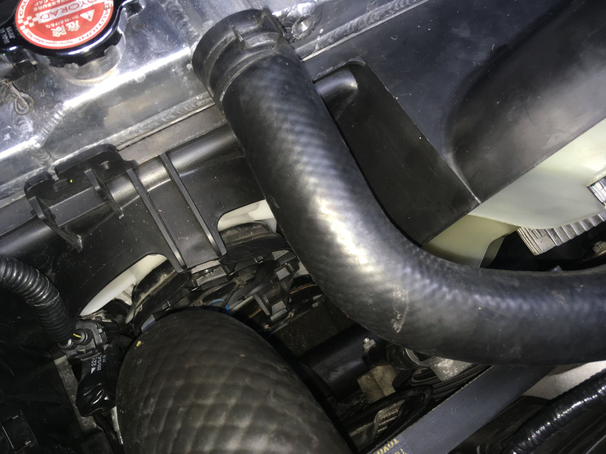
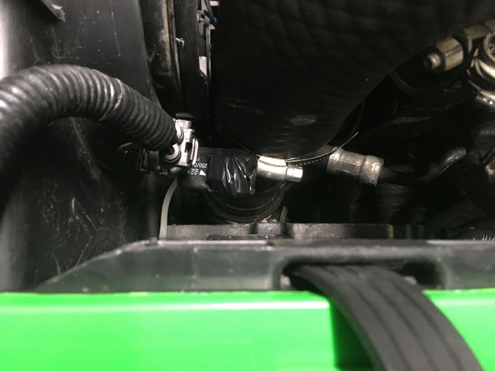
With the OEM Supra TT and/or Soarer 2.5L style OEM intercooler piping setup the fitment of the Supra TT 1997-2002 fan shroud has very tight clearance but it works. In fact Toyota revised the OEM intercooler pipe and hose to the throttle body in this location for model year 1997+ Supra TT's. I did obtain those parts but I didn't find much additional clearance with them. I may have had them assembled in the wrong orientation.
In any case the 1993-1996 factory intercooler piping and hose clearances will still work with the 1997+ Supra TT fan shroud.
Last edited by KahnBB6; 01-20-21 at 12:31 AM.
#972
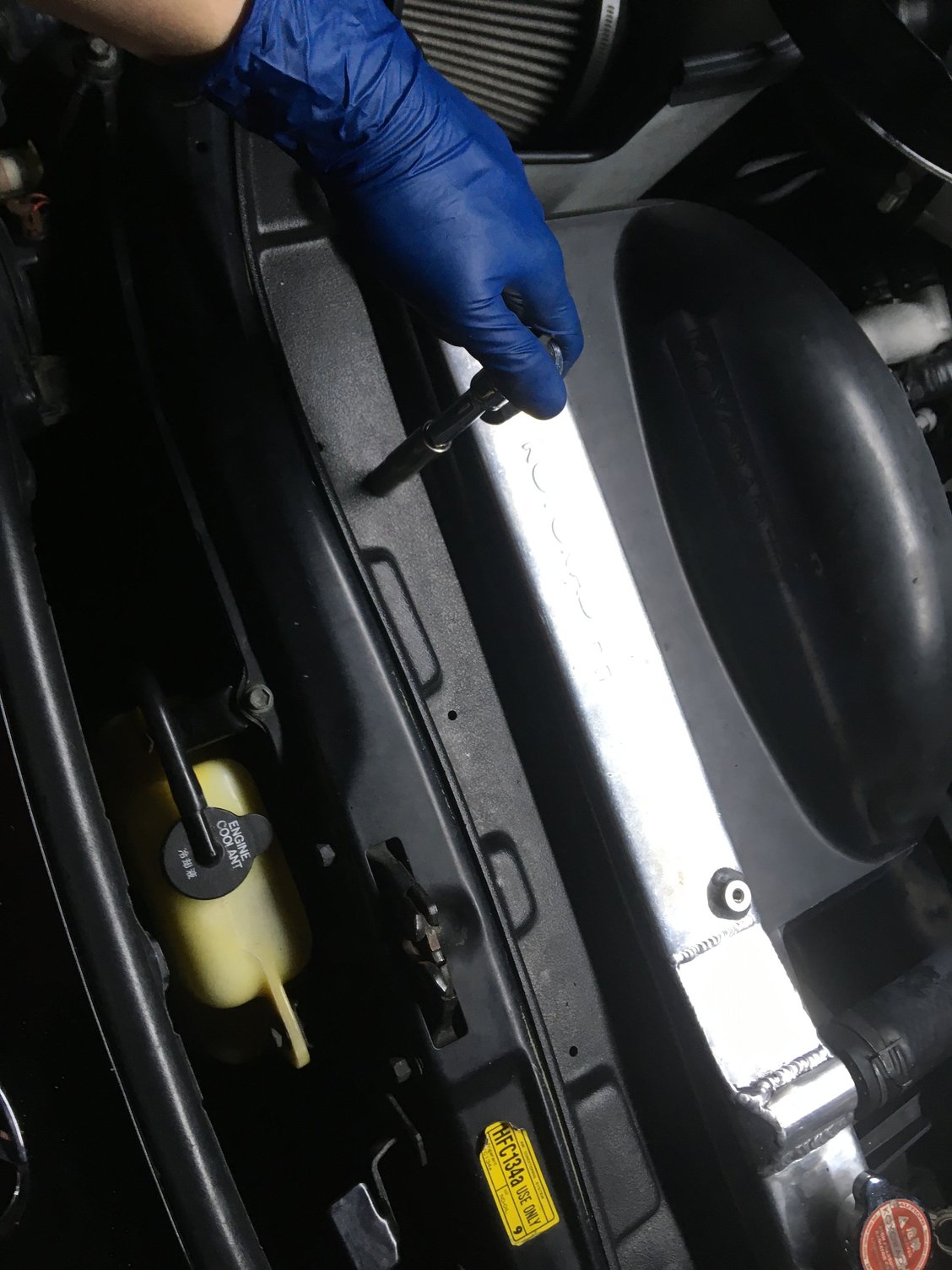
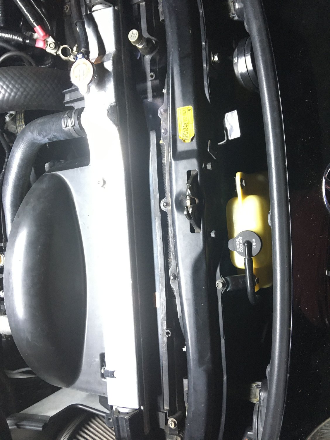
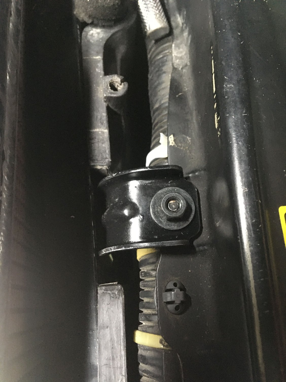
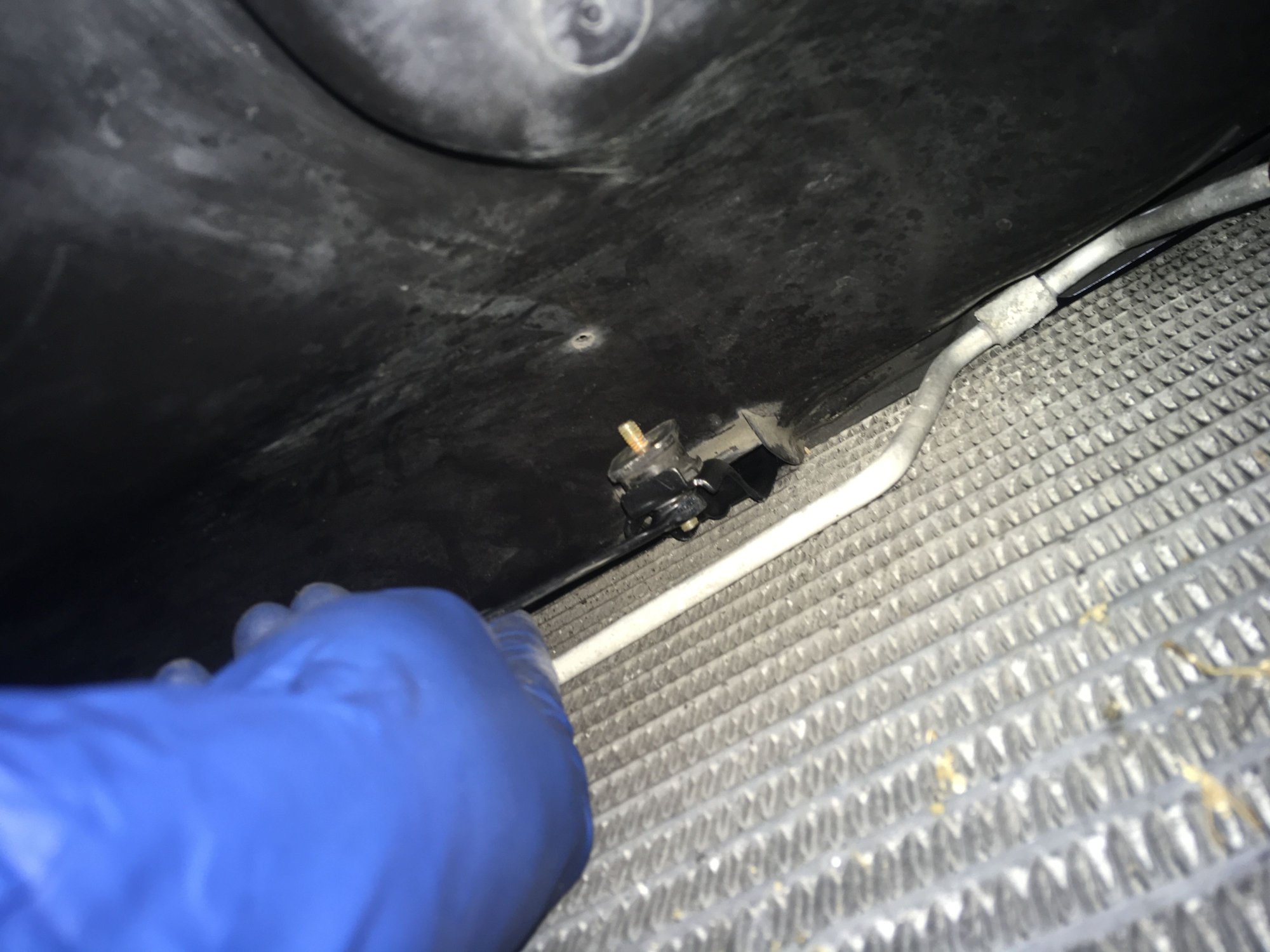
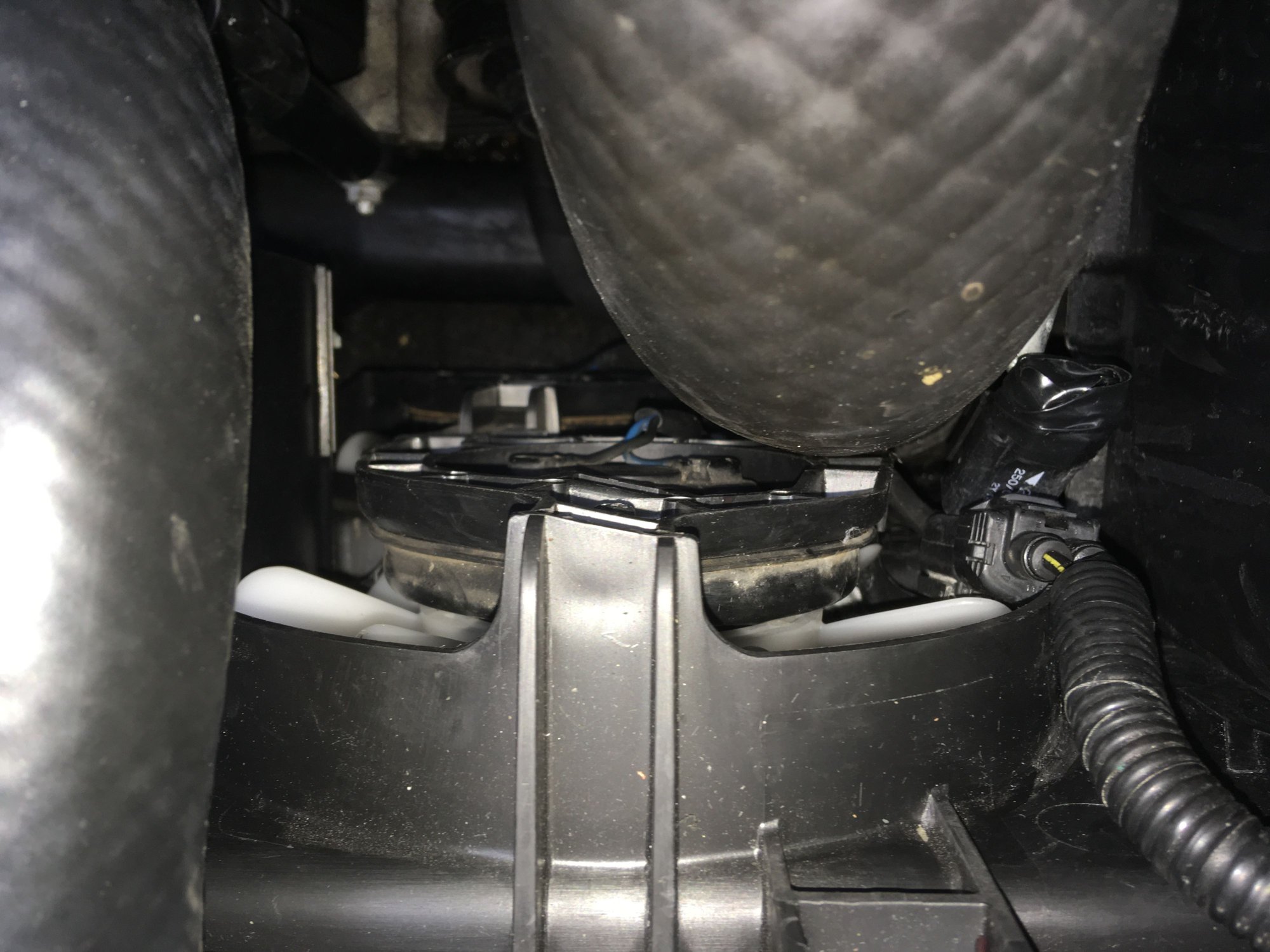
The Soarer 2.5GT Automatic factory condenser fan is designed to fit into an SC300 as a bolt-in assembly. The bracket setup for it has a specific order for installation and to get the metal fan shroud bolted to that upper bracket (once the upper bracket is bolted to the car correctly) you need a LONG 10mm thin wall wrench to tighten it in place.
I improvised by putting another wrench end against my 10mm wrench and affixing them together tightly with electrical tape. Even then it was still a chore to get to that one bolt from under the car.
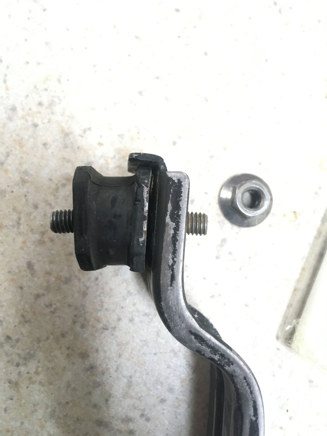
There are two pre-existing bolt holes on the SC for the Soarer 2.5GT Auto metal condenser fan shroud to bolt onto. The shroud has two rubber bushings.
Nearly all the bolts and nuts are still available to install one of these if you can locate one.
May interfere with front mount intercoolers. My car uses a re-cored factory side mount intercooler so it’s no issue for me.
—90179-06214 — Nut for condenser fan assembly top mounting (near the top of the radiator underneath the SC's upper plastic cosmetic cover over the A/C condenser)
—90119-06330 — x2 Bolts for lower condenser fan assembly mounting
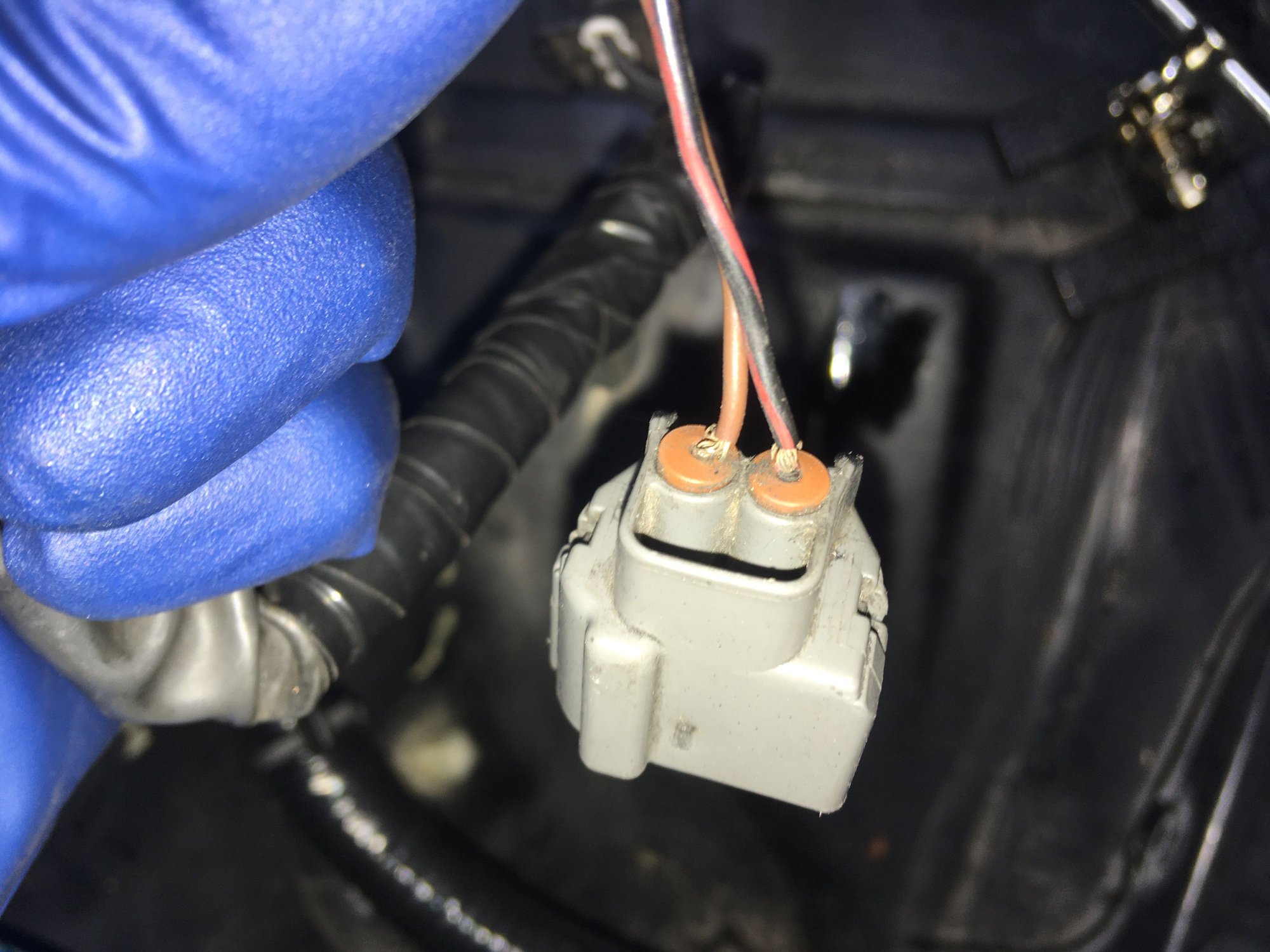
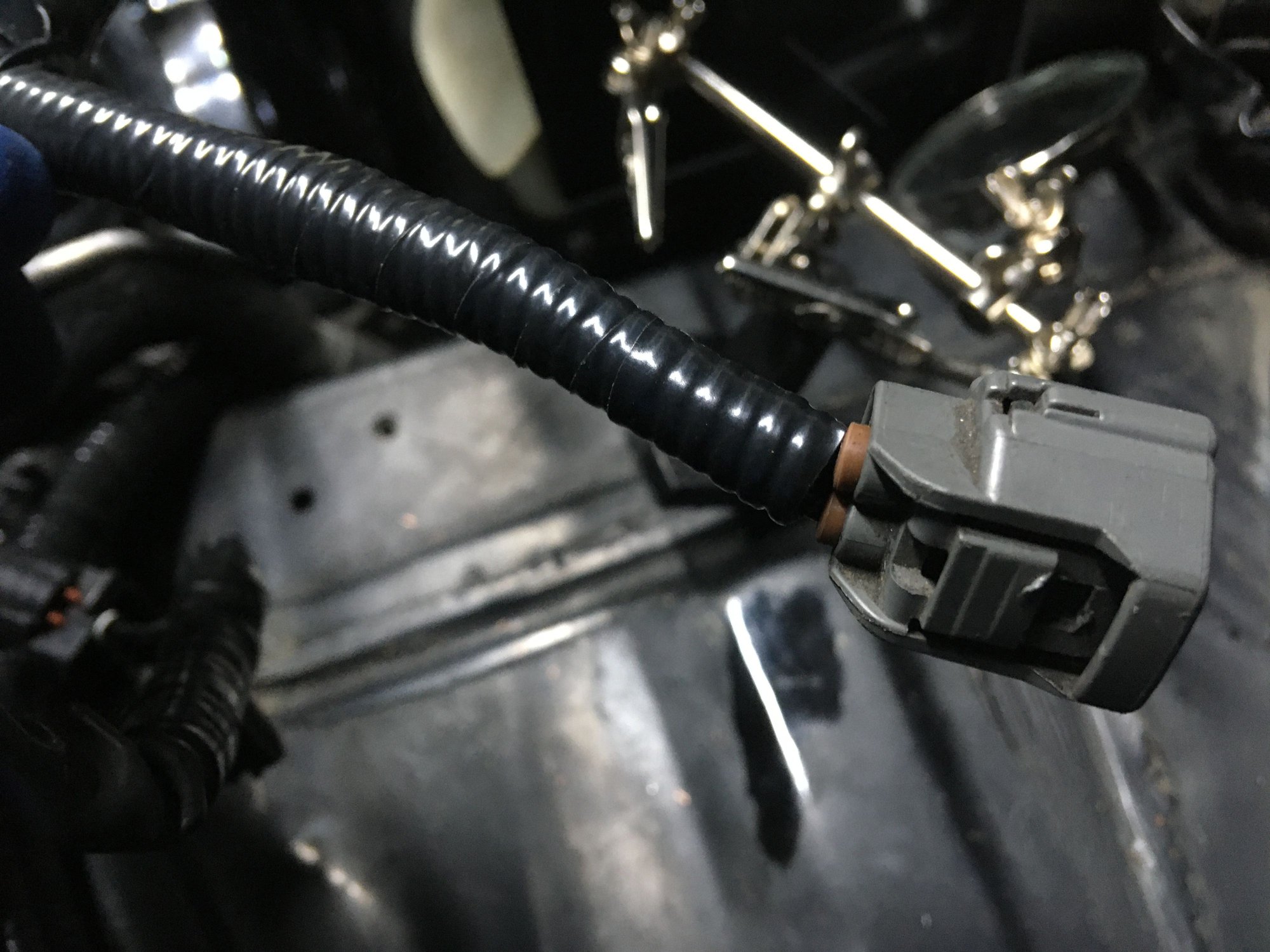
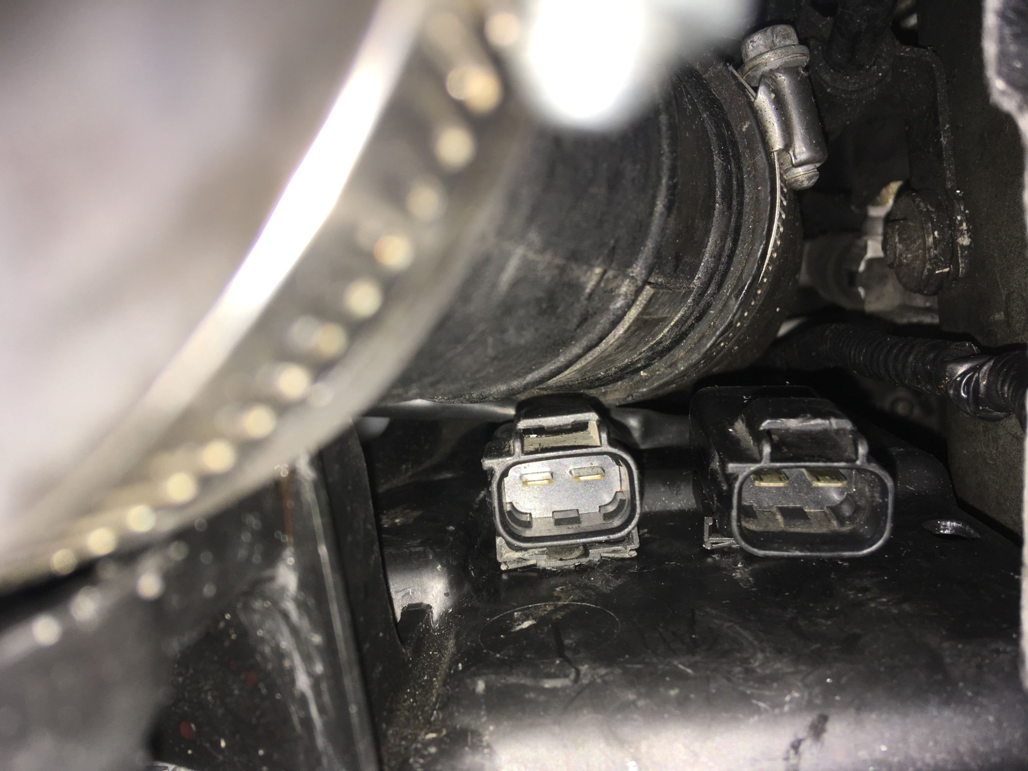
—82711-2B640 — Fan Motor Connector Clip/Clamp Plastic (if needed for USDM Supra TT Automatic A/C condenser fan connectors or Supra TT aux fan connectors)
Last edited by KahnBB6; 09-23-21 at 03:48 AM. Reason: Added part numbers
#975
Here are most of the relevant OEM and aftermarket part numbers that I used for all of these projects here for those interested:
--16711-46200 -- 1997-2002 Toyota Supra MKIV Turbo fan shroud (dual auxiliary electric fans) (discontinued)
--16361-46070 -- 1993-2002 Toyota Supra MKIV Turbo fan motor blade (x2 in this application)
--90099-04117 -- 2JZ-GTE Auxiliary Electric Fan Blade Bolts To Motor (x3 per motor)
--90099-04119 -- 2JZ-GTE fan motor 46060-type fan mounting bolts (x3 per motor and use washers with 97-02 Supra TT shroud)
--Common Toyota 10mm bolt with integrated washer (not too long) for mounting the newer 50020-type fan motor to 97-02 Supra TT shroud
--90980-11237 -- OEM connector for 2JZ-GTE aux electric fan
--82998-12480 -- Terminal repair wire for 90980-11237 aux electric fan connector (x2 per connector)
--All Soarer 1JZ Automatic condenser fan assembly parts save the mounting bolts, a few nuts and the motor itself are all discontinued-- you just have to find one of these as complete as possible, dismantle the assembly to sand down, paint and restore it the way I did. They are incredibly overbuilt parts, however and can be made to look nearly brand new with enough effort.
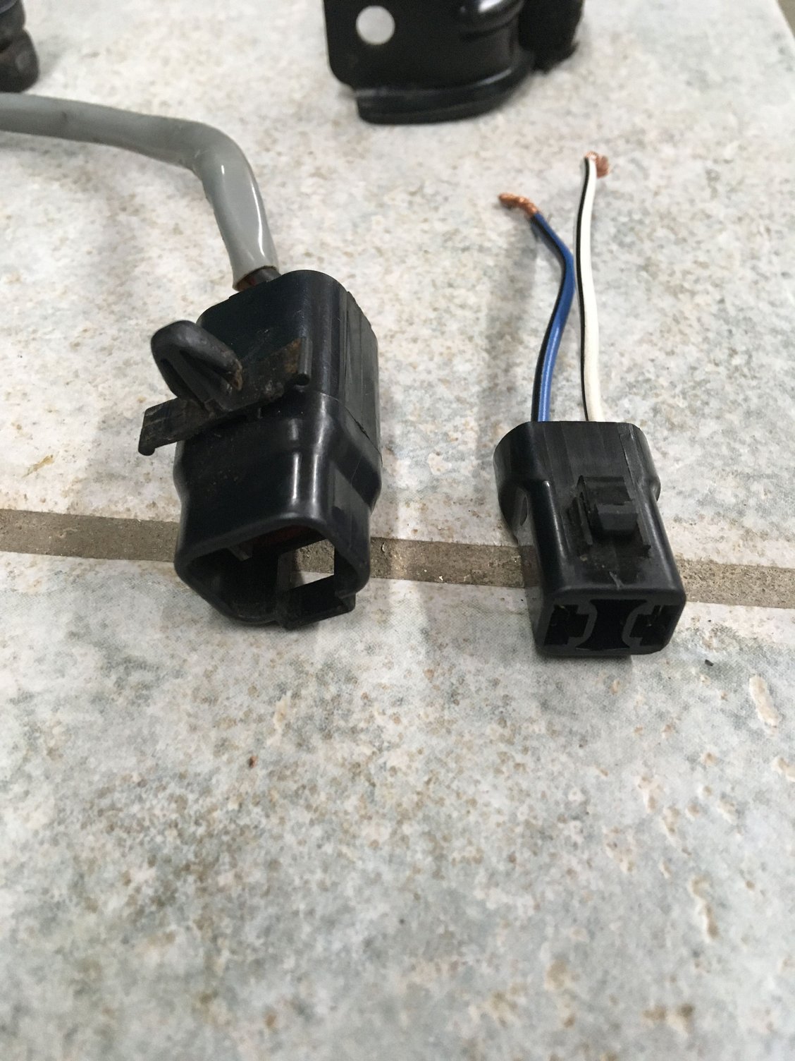
--The Soarer 1JZ Automatic condenser fan used its own type connector which was not identifiable so I just re-used what came with it. In this application a Delphi aftermarket weather sealed automotive spade-type connector would suffice if the used fan motor assembly doesn't come with one.
--Various lengths of marine grade wire in appropriate colors (red, black, white, blue, yellow, green, etc.)
--10ga for the main fan circuit power feed and ground to the Mishimoto ground-switching fan controller relay unit
--12ga for the immediate fan connectors, 8ga and 4ga for larger ground connections
--2/0 for engine block and battery additional grounds
--12ga for the 97+ fog light harness and fuse
--12ga for the HID system power feed and its twin 20A fuses
--16ga wire in various appropriate colors for very small current 12V Switched relay trigger wires
Littelfuse compact Power Distribution Modules for small 280-style fuses and relays purchased from Mouser Electronics:
--PDM31002ZXM -- Littelfuse Fuse Holder for 280-style components including small relays (metal end bracket sold separately)
--868-964 Littelfuse -- 90-degree angle mount for the above Littelfuse PDM unit
--12129493-L -- Aptiv Automotive Connectors Female (280 Series, larger cable size acceptance I think)
--12077411-L -- Aptiv Automotive Connectors Female (280 Series, up to 5mm wire but a little more can be squeezed in)
--301-1C-C-D1-12VDC -- Song Chuan Automotive Relay ISO280 (30/40A) (Data sheet and pinout diagram on website)
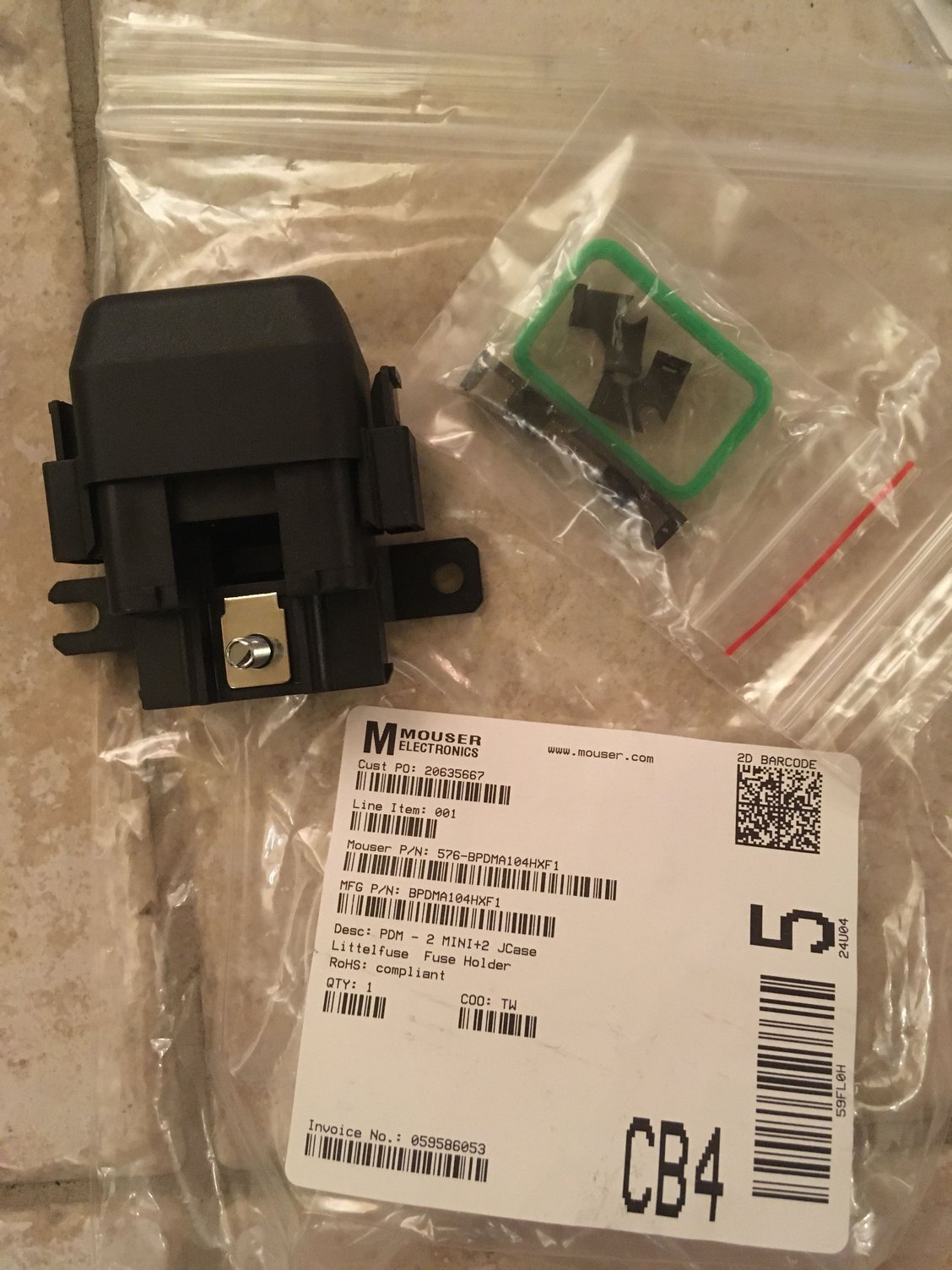
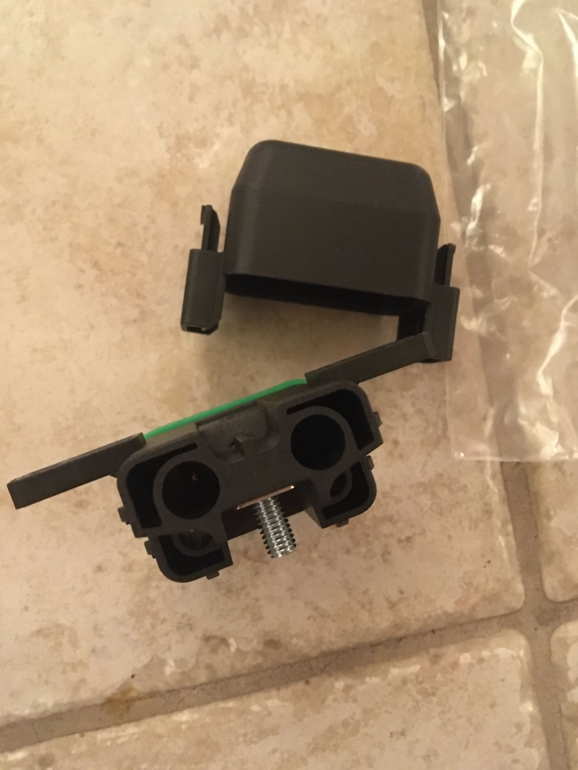
--BPDMA104HXF1-- Littelfuse Fuse Holder PDM - x2 MINI fuses + x2 JCase fuses w/ Mounting Feet
--JCAS030.X -- Littelfuse Automotive JCase fuse 30A Pink (x2)
--x2 generic 20A MINI Fuses
--12015858-L -- Automotive Connectors Female (280 Series) 4-6mm wire acceptance
Purchased from EGIS Mobile Electric:
--2012B -- EGIS Mobile Electric -- 250A compact ground connection busbar sealed 12 position M8 (black)
--4611B -- EGIS Mobile Electric Connector Kit (for 4611B) MX-150 12P w/14-16AWG Terminals (I was able to barely squeeze in a couple of 12ga wires with some Dremel boring and VERY creative use of heat shrink tubing placement but it was not easy; the rest of the ground connections were applied to the M8 bolt and the 4GA ground wire I made for it)
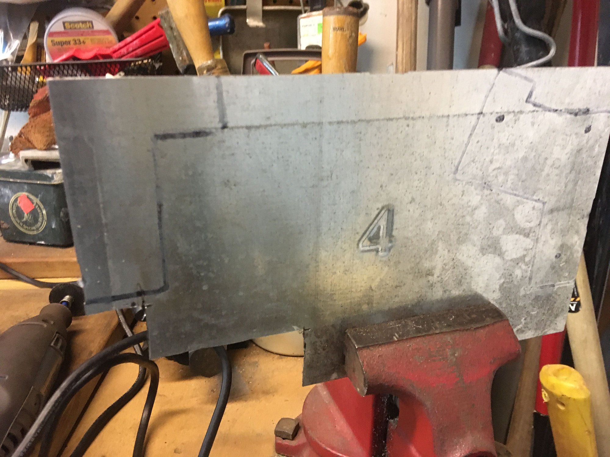
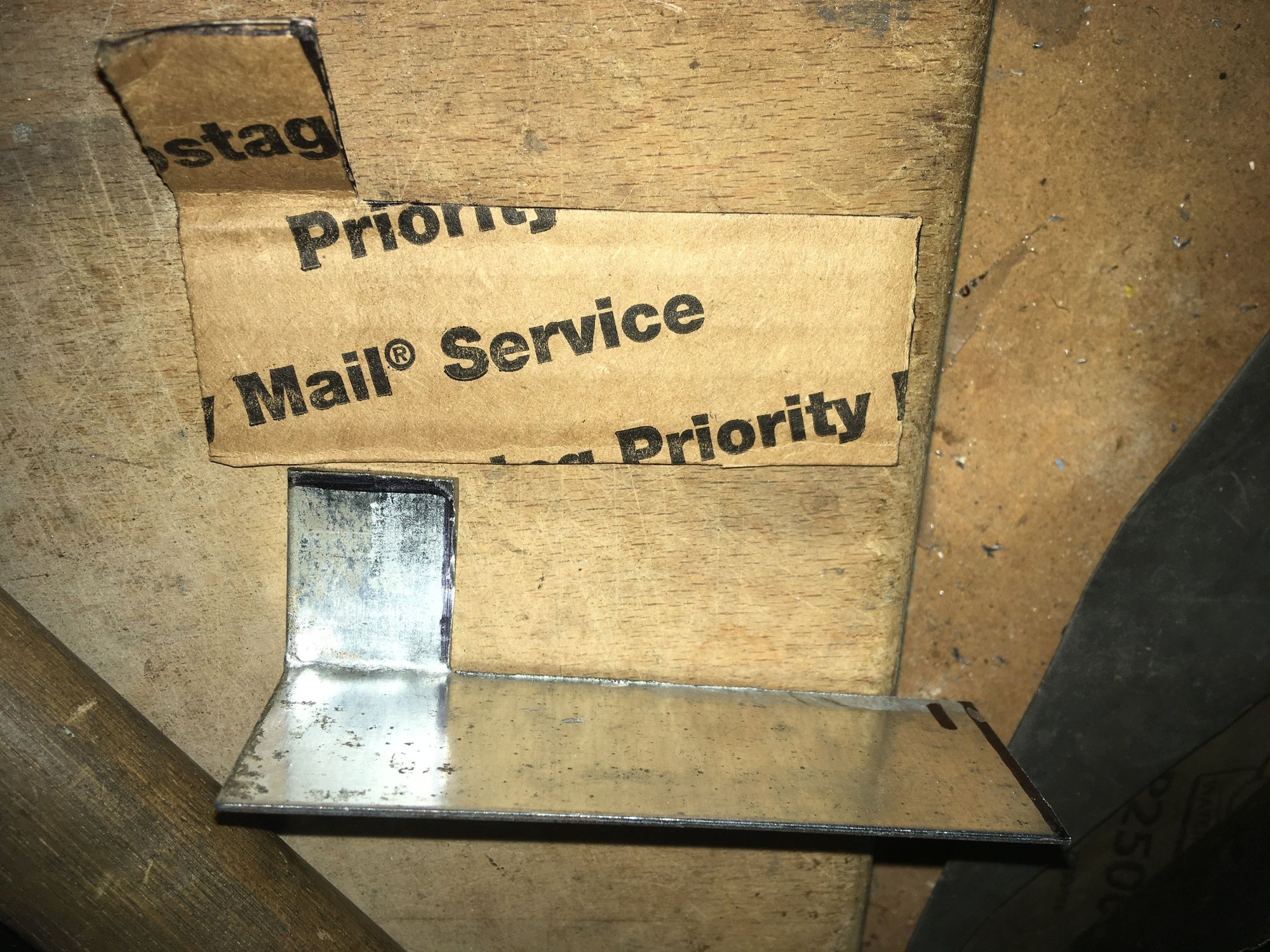
--Final brackets for the Littelfuse PDMs were made up in cardboard templates for testing and fitting, traced onto a thin plate steel sheet and then cut out with a Dremel tool using a cutoff wheel attachment. Evening up and de-burring was done on an old stationary electric shop motor with a grinder wheel on one side before scoring with 80 grit sandpaper, primer and final black paint (infused with some polyurethane I believe) were applied.
The 12VoltPlanet standard automotive relay and standard fuse holders that I had used back in previous posts were both removed in favor of the Littelfuse PDMs. If anyone is interested in those, just go to their website and keyword: "Standard Mini Relay & Blade Fuse Holder".
When ordering things like these from Mouser, check through every part to make sure you have EVERYTHING that you need. Littelfuse PDM components and the various fuses, relays and terminals and even mounting brackets are usually all bought piecemeal so you need to research all you need and make your own kit when you order.
I hope this helps anyone wanting to create their own OEM-grade compact auxiliary fuse and relay setup in their tight SC engine bay.
Last edited by KahnBB6; 02-08-21 at 12:40 AM.


