When you click on links to various merchants on this site and make a purchase, this can result in this site earning a commission. Affiliate programs and affiliations include, but are not limited to, the eBay Partner Network.
Here's where I started. I bought a new Pittsburgh 3.5-ton hydraulic jack to replace an old one that was giving me issues (NEVER chance it with a faulty jack) and a new set of jack stands with a locking pin as part of their design.
I drained the oil and coolant:
I removed the main intake tube, upper intercooler pipe and some other parts:
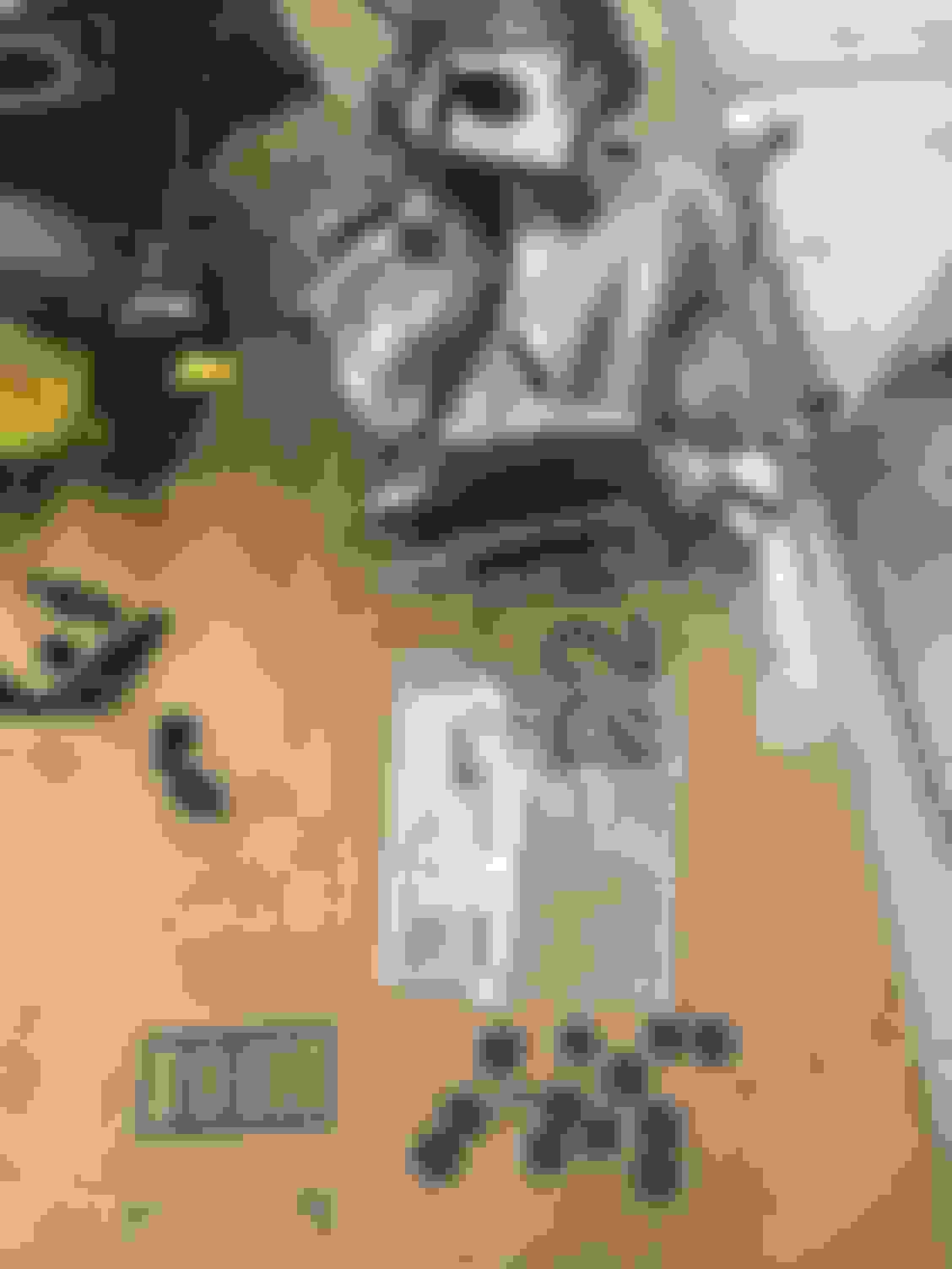
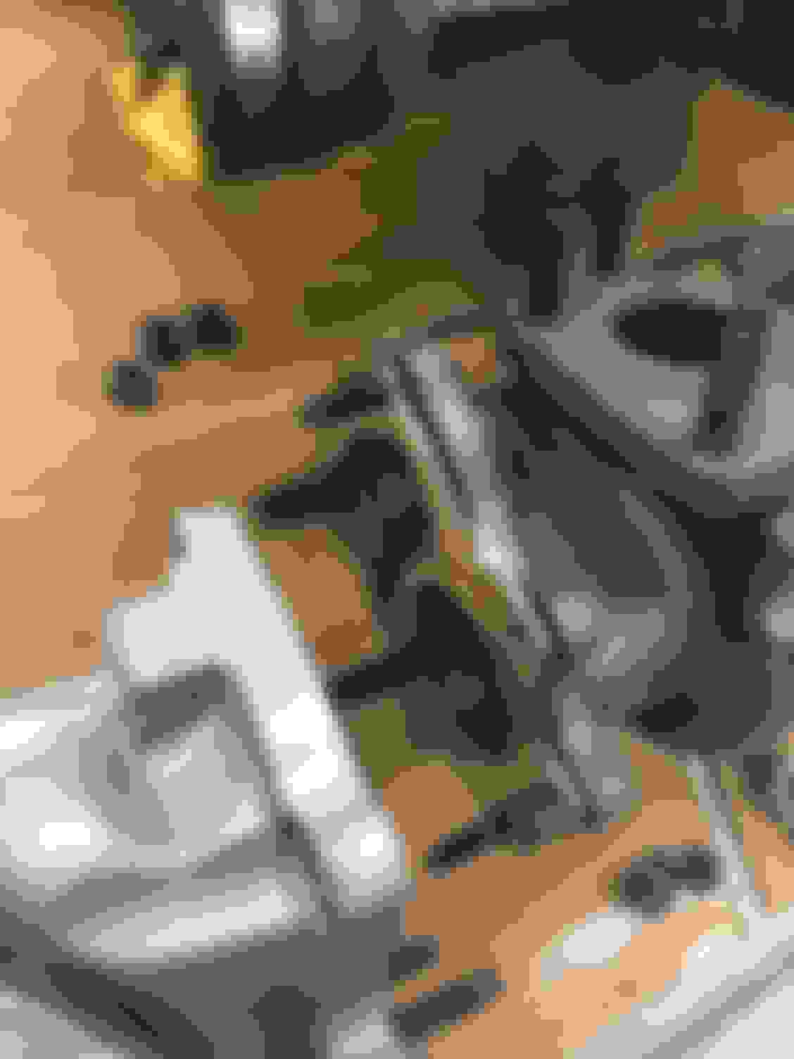
The floor I had set aside with cardboard laid down was already beginning to accumulate a good deal of parts:
Now at this point while I was still removing all the upper turbo intake parts that sit on top of the two turbos and heat shield I realized that it's MUCH easier to wait until taking off the Intake Control Valve assembly at the rear top of the turbocharger #2 before attempting to remove the last couple of vacuum lines from that large metal vacuum line assembly.
I let that metal vacuum hose assembly hang for a while until I had all of the upper tubing above the heat shield (other than the metal water line) removed. Then it was much easier to remove those last two vacuum lines holding onto the metal vac line assembly. A set of long bent hose clamp pliers are VERY useful to do this.
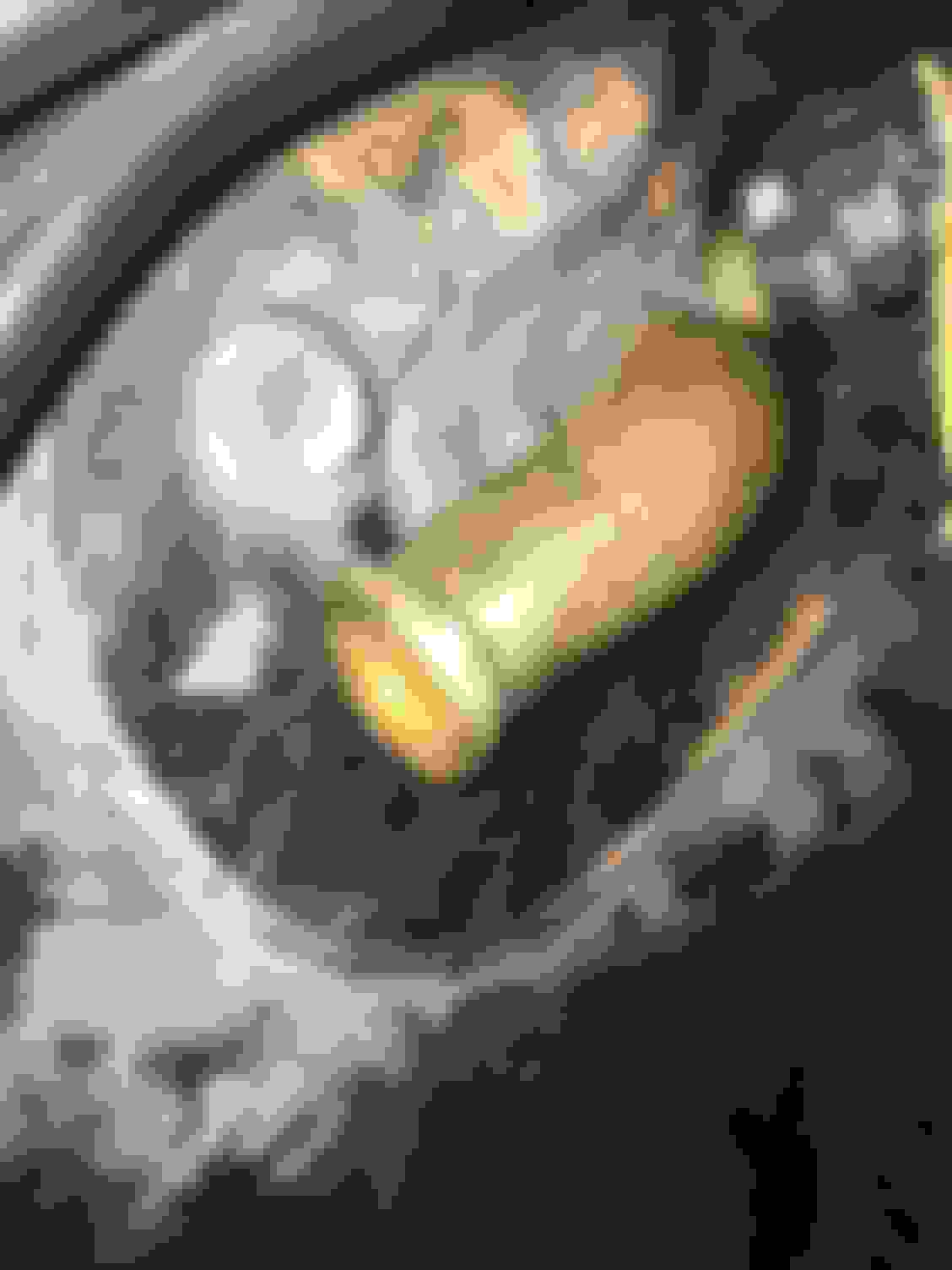
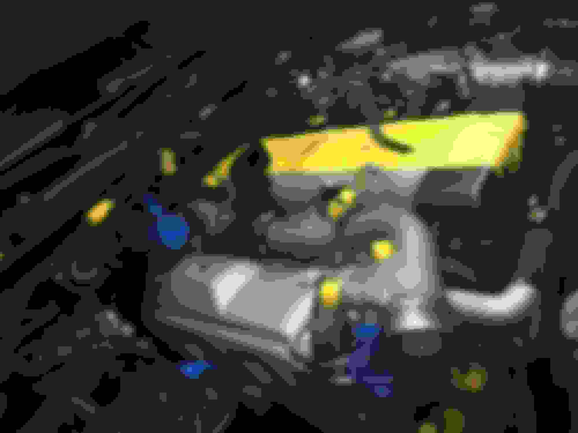
Sorry, no direct pictures of that but once you get there you will see exactly what I mean. Here's a picture of my using those particular hose clamp pliers to remove the front turbo coolant hoses to illustrate how far down you can take such a tool to get at hard to reach OEM tension clamps:
Now the upper air intake hardware is almost totally removed:
Finally when taking off the turbo heat shield (boy, this thing got very rusty within only a couple of years after I cleaned it up to begin with! This is why I repainted my spare heat shield with VHT 2000F silver color paint) it became apparent as to why the long metal coolant bypass metal line gets slightly bent out of shape when taking the turbos off. The reason is that there is just no way to not move it around a little bit. This makes it a challenge to get it in place for the little 10mm bolt that holds it in place upon re-installation. Still, it's impressive packaging by the Toyota engineers:
Okay, now once you get to the Exhaust Gas Control Valve Housing this is where it gets tricky. I don't think anyone hasn't had a hard time with this part of the removal (or reinstallation). Some people have suggested getting a Snap-On 14mm stubby wrench and a slide hammer... and I tried that... but I really like Beezupra's method best.
And I'll fill in a couple of details but I'll let Beezupra himself give you his method:
Originally Posted by beezupra
Regarding ***** bolt - Clearly the 14 mm stubby and prybar works for most people, but I managed to booger up the nut and this approach failed me. (Or I failed the approach, lol). I am adding an alternative method for ***** bolt removal that should work great before stripping the ***** nut corners, and worked for me even with after stripped.
There are 2 studs that attach to the lower end of the EBV tube to the Exhaust Gas Control Valve. At least one of these is totally in the way of accessing the ***** bolt with a socket. These studs have a star pattern on the end, and I was able to readily remove them with a 6 point Torx socket labeled EP8. At O'Reilly's, I bought a set of sockets called Bolt Extractors. These are the coolest tool I've bought in a while - they pressure a bolt head or nut in the middle of the flat section, instead of on the corners.
After fitting the socket-like 14mm Bolt Extractor over the ***** nut, I then added a short 3/8" drive wobble extension. Watch and feel the fit of the socket over the *****-nut; the junction between the socket and the wobble extension will want to "straighten out" which lifts the socket so it isn't squarely on the nut all the way around. Use a finger to push this socket/wobble junction inwards towards the body of the EGCV valve, which will max out the "wobble" in the wobble extension, to keep the socket fully seated on the nut. See if you can keep a finger there to maintain the proper socket seating while torquing your wrench with your other hand. I then tapered down to a 1/4" drive segment to clear the downstream lip of of the EGCV with minimal angle loss, then back to another longer 3/8" wobble extension. (If they make 1/4" drive wobbles, maybe that would have been easier, but not in my toolbox.)
I would recommend these bolt extractors any time one has a tough nut to crack - they will prevent corner stripping in addition to dealing with corner stripping after it is too late.
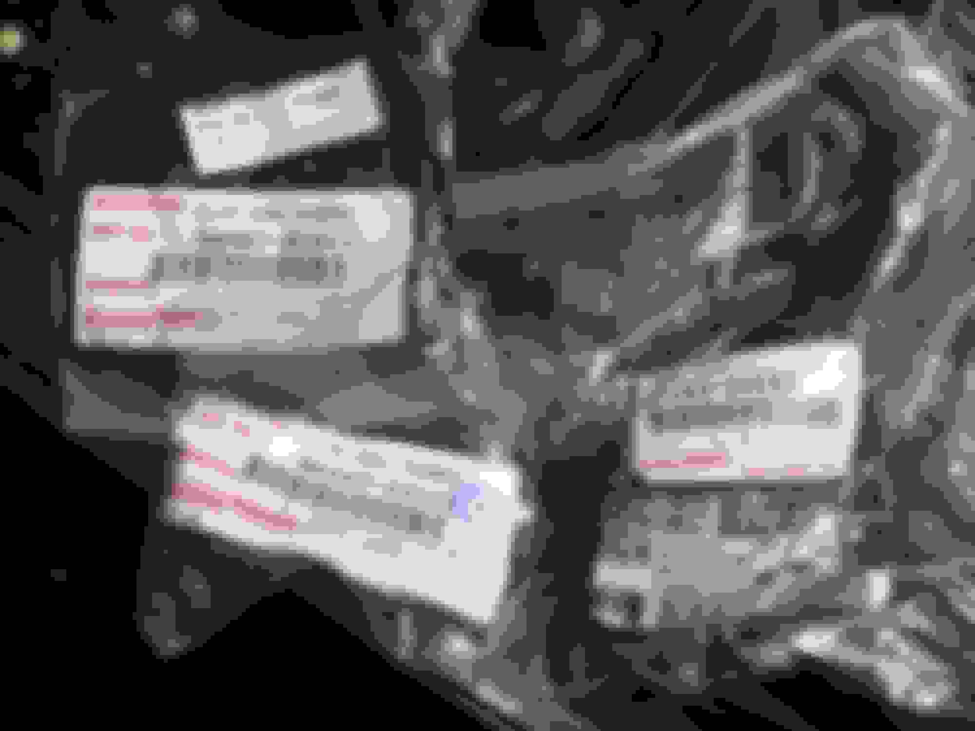
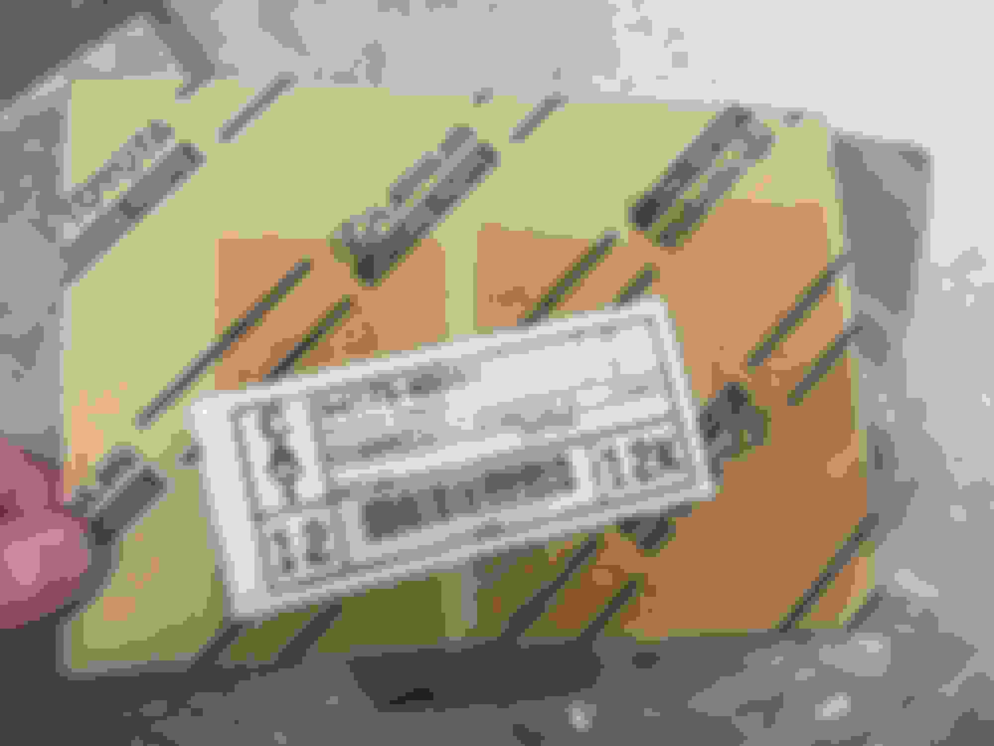
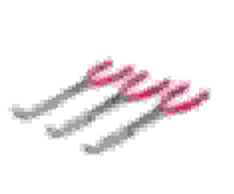
Below is a photo of each tool I described above for Alternate ***** Nut Removal:
One more tip to lessen future *****-nut hassles. Buy new nuts, and I found a difference in what's out there. The last time I ordered these exhaust manifold/stud/EGCV nuts from an online OEM Toyota dealer, the ones I got were the type that have divots along each flat edge as pictured to the far right. IMO, these suck and are much more likely to round-off and get messed up. You can use a star/torx socket but I still think they are inferior. The other two pictured are sold as specific for this application, and I find are superior. Driftmotion linked here is an example of a source for higher-quality replacements.
This was like a light bulb going off for me! Brilliant solution to a very annoying problem (thank you Beezupra!)
Now what you can't easily do is photograph exactly what he's talking about because the confines are so very tight in there.
In fact you can FEEL the b*tch nut on the EGCV housing better than you can even try to see it or photograph it with a small cellphone. Imagine trying to see what is on the other side of a mountain ledge that you have yet to traverse from below. You can't.
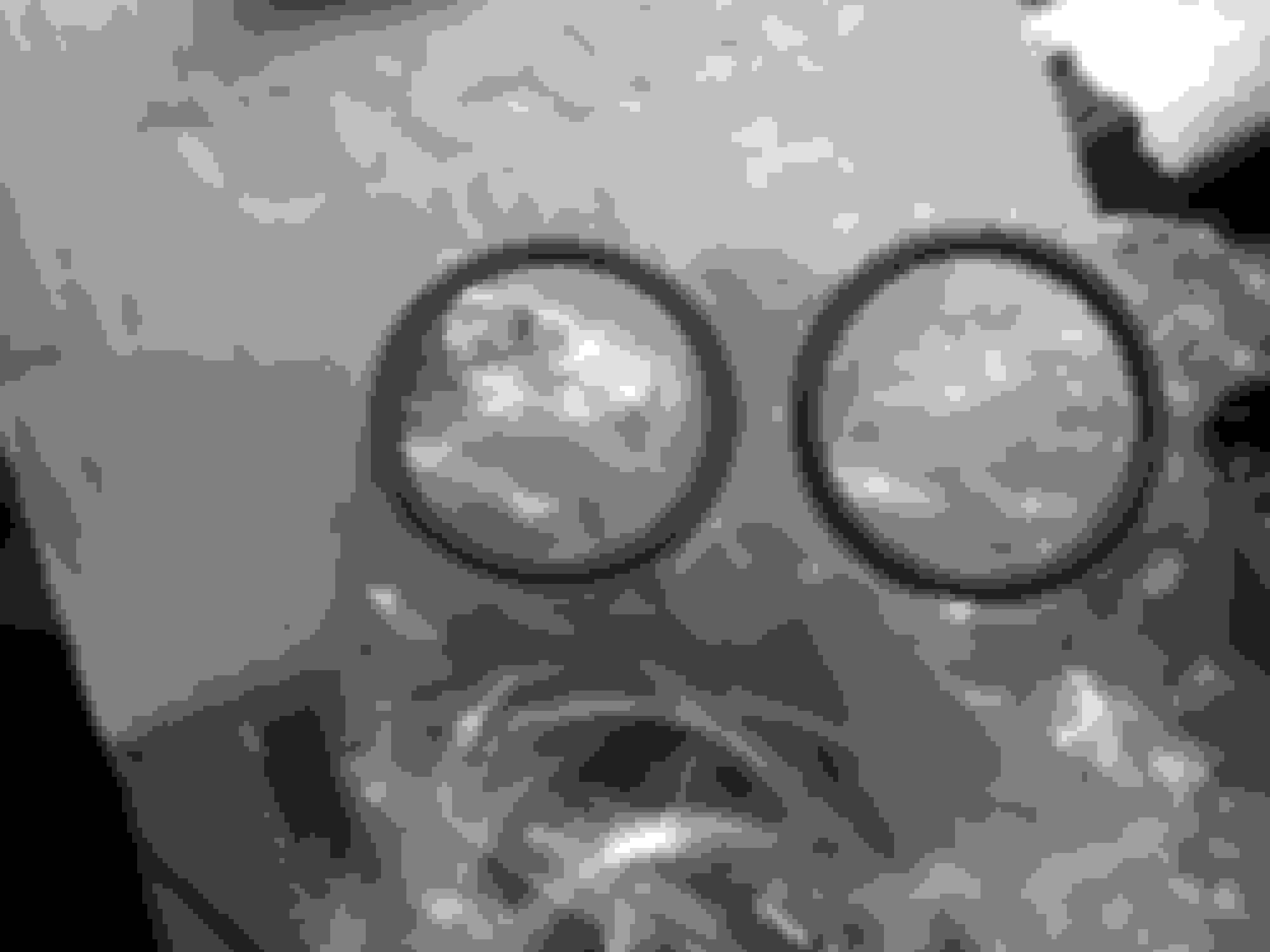
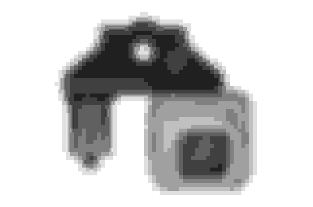
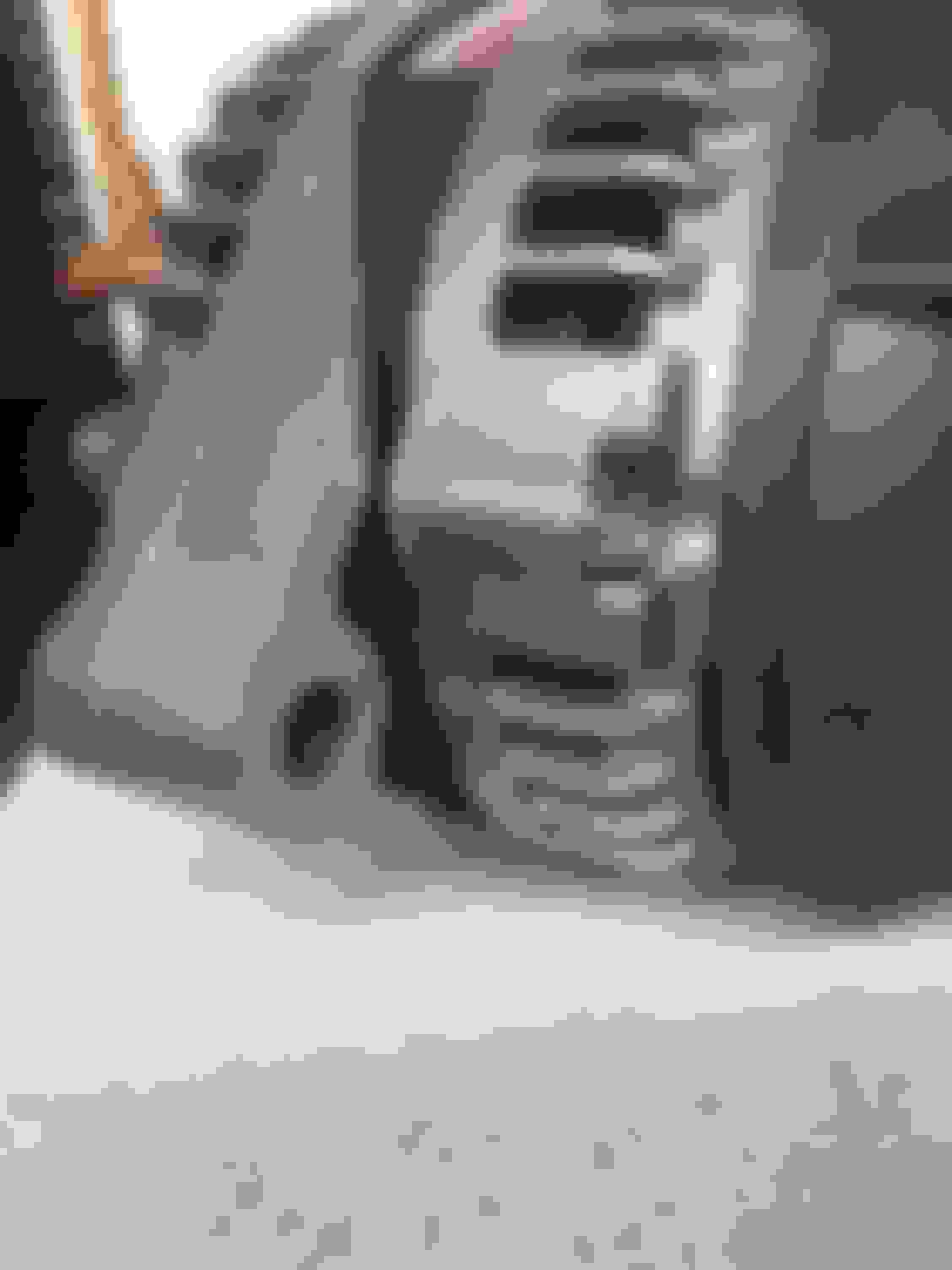
What I do have is a spare USDM TT EGCV housing to show you what you will not be able to see from under the car
As you can see, there is a lot of the housing material that is visually in the way of seeing the one difficult nut while looking from under the engine... or while looking down while standing over the engine.
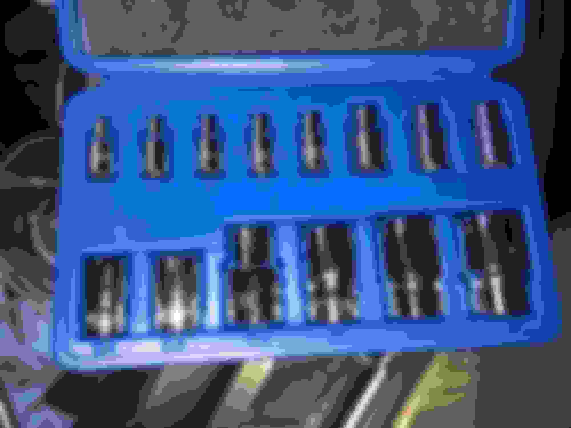
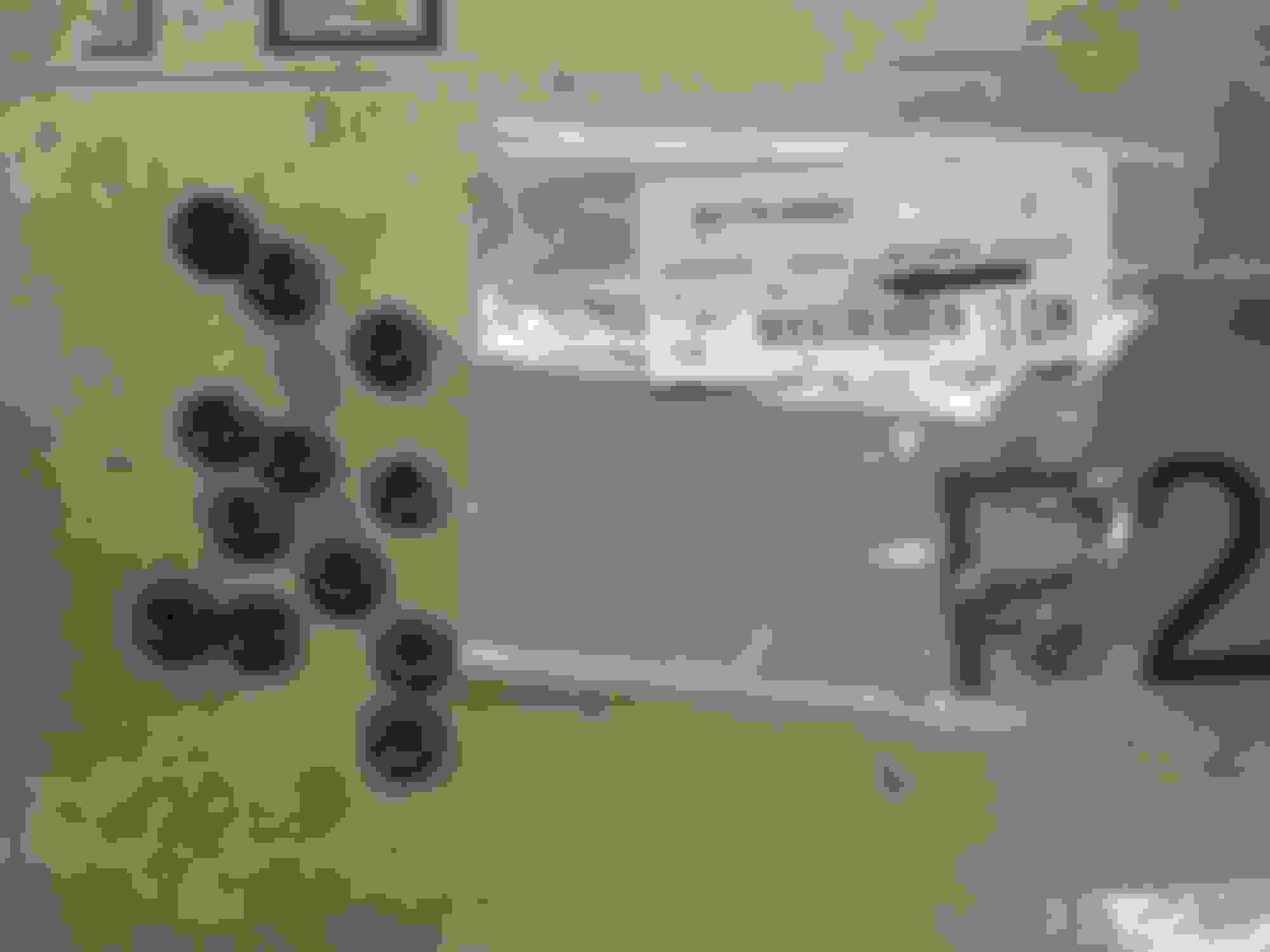
Beezupra also suggests removing the studs for the turbo transition crossover pipe and O2 sensor to get better access with the extractor socket and various extensions. This is required and that is one of the reasons why you'll need the Neiko Torx socket set:
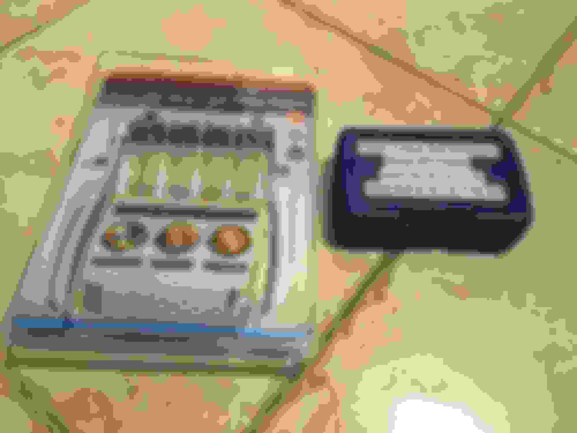
And here you can see the Power Torque bolt extractor kit that he recommends and after that the various combinations of socket extensions. I actually went back and forth between a couple of lengths of the 1/4" short sockets that are recommended between removal and installation. The key thing is that he's right in that you absolutely need some of the wobble angle bend when doing the removal and re-torquring later on (if you plan to re-install new stock twin turbos).
You need to get a pretty good seating of the bolt extractor socket on the 14mm nut and there is really no conventional socket that will do it. You really do need to step down to 1/4" before going back up to 3/8" after that "ledge" of the housing has been cleared.
You will be able to feel for all of this by hand and at one fairly difficult angle you can *kind of* see the extractor socket on the nut to determine if you have it seated properly. But you still need to be facing under the car to break the bolt loose and especially re-torque later with your torque wrench.
Oh, also spray PB blaster all over each of these nuts and let it set in.
Once you have this method set up that nut should come out fairly easily. It's all in the right method. Also as Beezupra suggests, (and also Toyota in their factory manual), just replace the nuts for reinstallation. Don't re-use the old nuts. They're cheap to replace and you have a good chance of damaging them when removing them.
Now at the rear of the engine there are two water bypass hoses that should be replaced while you're in here. You especially should if your engine has significant mileage on it. I replaced these with two brand new hoses and new clamps even though I only had 6k miles on the engine build at the time
Also, very critically if you happen to install these hose clamps on an engine stand, make sure you orient them so that you can remove them with hose clamp pliers while under the vehicle. I didn't think of this when I first put my engine together and boy was it a PITA to turn these things around. I eventually resorted to just cutting one perfectly good hose in half... which uh... might possibly be the reason I had to replace that one >_>....
And yes in case you were wondering I somehow did not realize that my engine block was not painted before I assembled it back in 2017. I asked the machine shop to do it and it *looked* like it had a light black-bronze color paint on it but I guess it was so clean at the time I had no idea that no painting ever occurred. Oh well.
Finally I was able to start removing the turbocharger assembly.
There is no need to remove the stock exhaust manifold to do this (unless you want to afterward in order to put on a different manifold for a single turbo setup) and it's better to leave it on as there is a specific torque pattern that you need to follow if you do plan to install new stock twins.
A couple of things:
--This is where the super long 14mm non-ratchet style VIM wrench will come in handy. That and a LOT of PB Blaster sprayed onto the nuts.
--The SC300/400's Heater Control Valve assembly will be in the way. You have to disconnect it partially and unbolt it from the chassis as well as disconnect the lower HCV hose to have enough room to move the turbos closer to the shock tower for removal (you'll have already disconnected the upper HCV hose to get some of the upper turbo hardware off earlier).
--You will find that you have to remove most of the studs on each turbo's mounting flange just to get it off and out of the car. I removed all but one on each side and left a nut loose on there to keep it held in place until I was ready to lift it out.
--There is really only one way to lift the 66lb+ assembly up and out of the tight engine bay. I could not avoid scratching up some of the rear firewall metal and part of the shock tower. It's brutal. You almost need to have one boot standing where the air intake box or cone filter should be.
*Watch your back while doing this!!*
Also... *watch your footing while doing this!!*
These things are heavy and you don't want to hurt your back or trip backward while trying to lift them out of the car or lift them into the car.
--I kept some Rustoleum kitchen appliance epoxy paint handy which sort of closely matches my stock Lexus 202 Onyx Black paint color. I also keep a bottle of 202 Onyx Black touch up paint handy. I repainted the scratched areas with whichever made the most sense (the epoxy on any exposed metal and the touch up lacquer on any metal that still had primer covering it). I had to do this again once I had my new turbochargers installed.
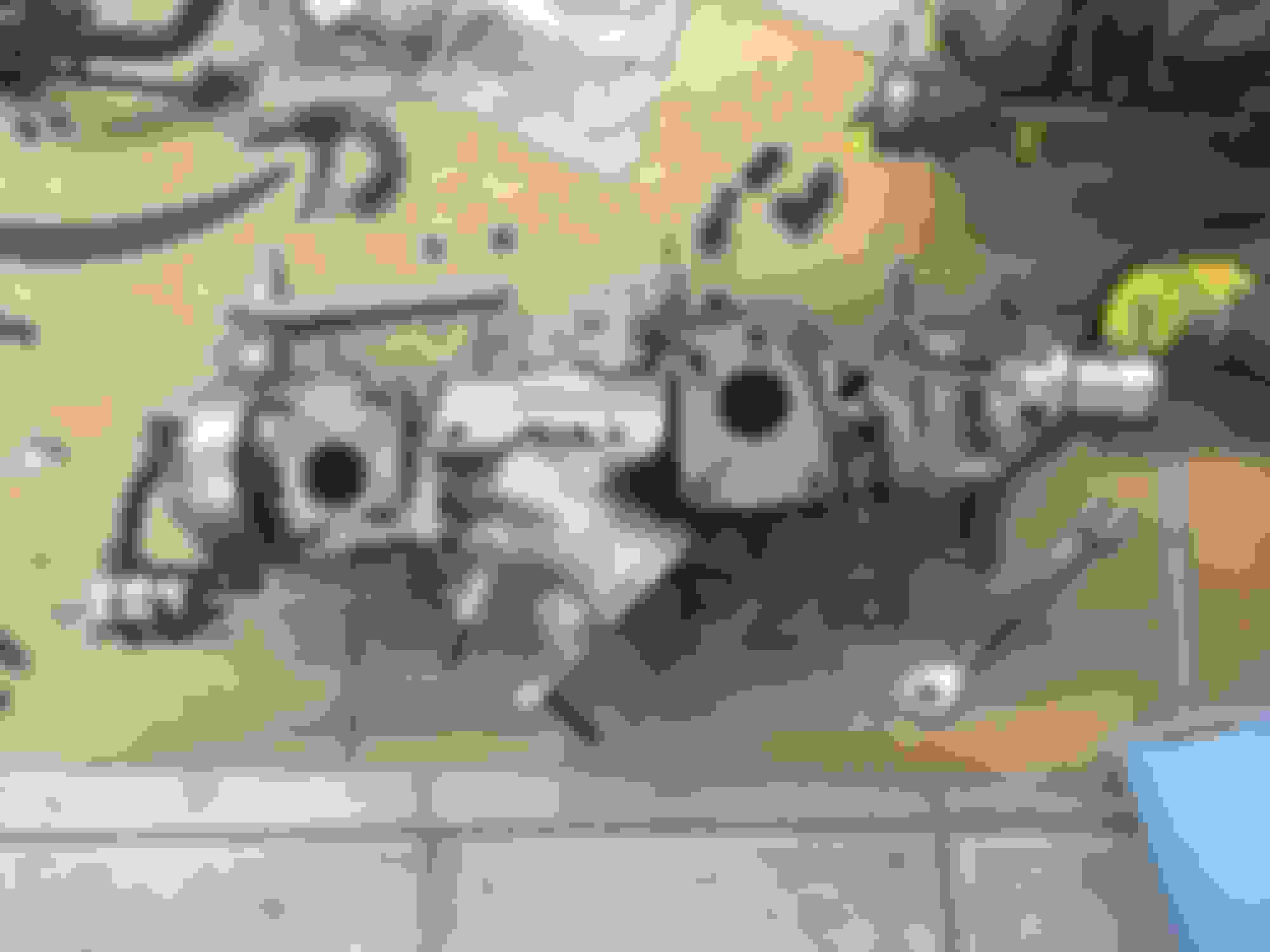
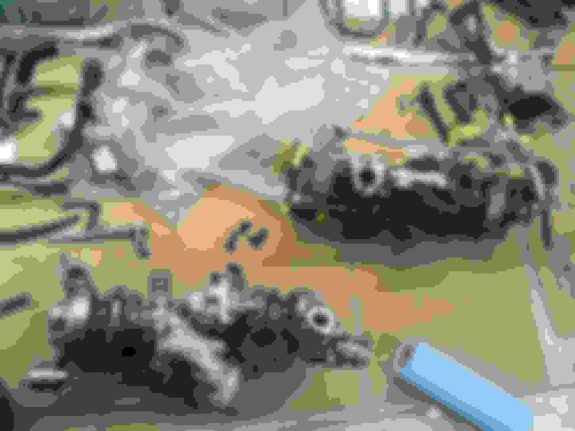
Finally, here are the turbos removed from the car. This is a very methodical process that pretty much anyone can do but what a tedious ordeal it is just to remove them. I was now halfway there, however! Have to think of the big picture!
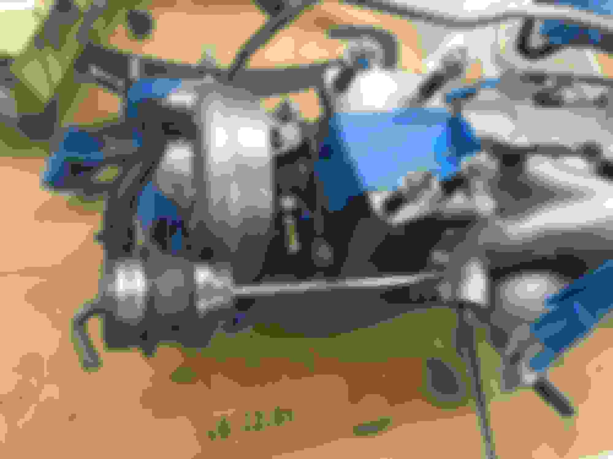
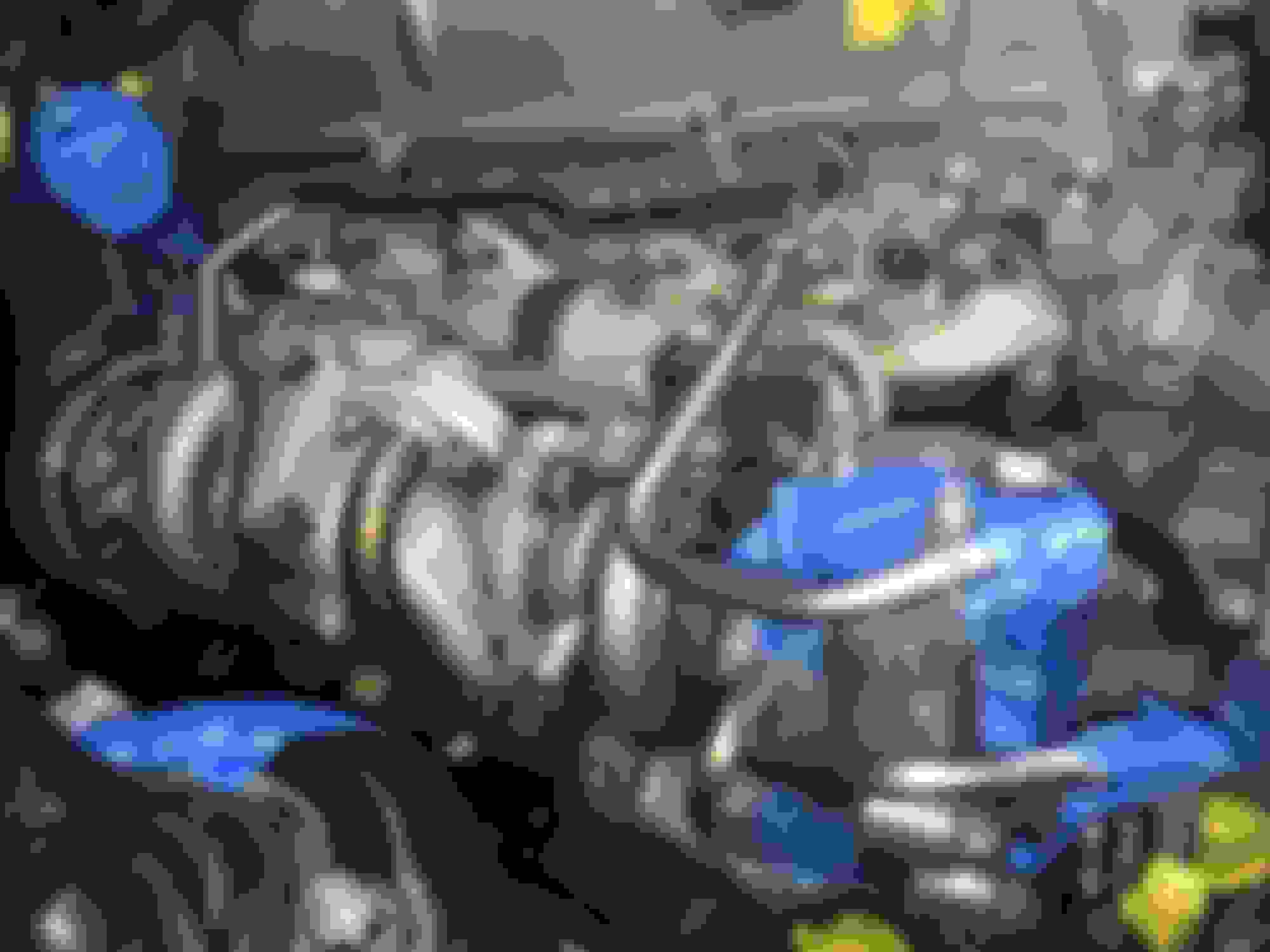
And here's the 2JZ-GTE engine bay with the turbochargers removed. It almost looks like a 2JZ-GE now
Now I had to address a couple of extra "while I'm in there" things. First, this metal line that looks like it is an A/C drain had some surface rust on it. So I put a lot of newspaper down and used painter's tape where necessary and got to sanding off the rust on its surface. Then I wiped it clean with alcohol and had to get really creative with the angles I'd use to spray it with VHT 550F primer and later VHT 550F black engine paint. It wasn't a perfect job but that drain line is now clean and protected for many more years to come.
Next, I had to do something about my old and leaking lower SC300 Heater Control Valve hose going to the heater core.
I ordered a new hose (Lexus P/N 87245-24290) and two new clamps for it (P/N 90467-22011) and got those installed. There's no way to get to this hose at the heater core with the twin turbos installed. I cleaned up the heater core's brass fitting and had to carefully bent part of it back into shape. Somewhere along the way the previous owner of the car or a mechanic must have bent it a bit.
That's better!
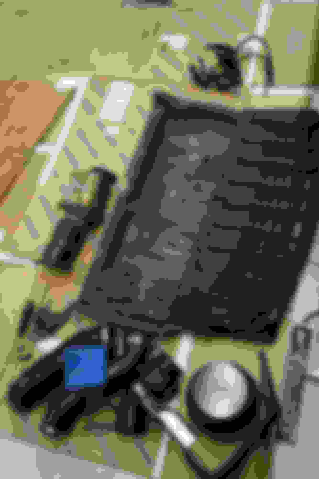
Now I had to get the rest of the replacement parts ready.
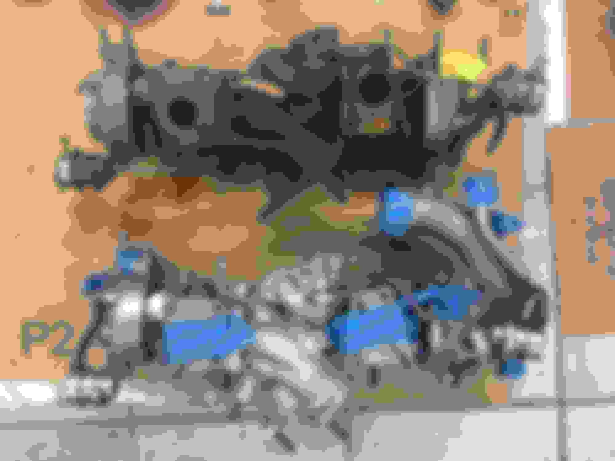
Look at how much the temporary storage floor filled up!
You'll also see that I took the exhaust side engine hook off, dunked it into a rust remover solution and fully repainted it in VHT 550F. There's never a better time if it needs to be done!
I had already sent out a set of spare MKIV TT front and rear CT12B's (I actually sent them out one at a time-- they cost about $750 each to rebuild!) to The Boost Lab of Tampa, FL. They did an excellent job of rebuilding and restoring these turbos and I highly recommend them.
Here's the OEM USDM 93-98 Supra TT turbo gasket kit (it's probably the same for all European/UK/Export 2JZ-GTE's):
Several small replacement nuts were ordered in case they were needed when putting on the new gaskets:
This time I de-rusted and fully repainted the center turbo exhaust collector housing in VHT 2000F silver paint.
The new front and rear multi-layer metal crush gaskets going onto the rebuilt turbochargers:
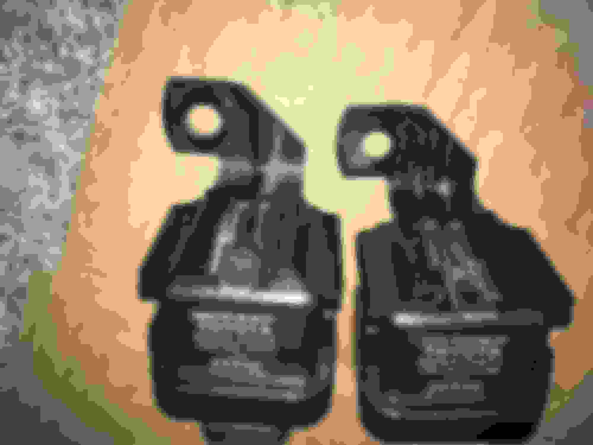
Comparing the outgoing 156k mile set of turbos with a blown #2 and the fresh set of newly rebuilt turbos:
The only issue that I had was the metal arms of the turbo wastegates both being bent slightly. They looked like they might over-stress the wastegate diaphragms so I asked The Boost Lab to correct this if possible. They did to an extent but... it didn't seem to be quite enough. I was able to get them a little more straight and sort out the #2 wastegate arm with no more clearance issues.
There was a problem when I tested them with my Mityvac however. The front one, despite looking shiny and new, held no pressure! Not good.
I finally decided to swap over both wastegates from my old turbos since they both pressure tested perfectly and were not at all bent out of their original factory shape. Someone probably tried to yank the bent wastegates off the other turbos while attempting to remove them from the original car they came from. Yeesh.
Anyway the other wastegates were swapped over, I made sure all the nuts were torqued correctly, I put everything back onto the turbo assembly just the same as it was on the old and worn out set and they were now good to go
I also had to clean up the "old" (by 6k miles!) gasket material from the turbo water bypass pipe before installing it with a new gasket. Various grades of sandpaper are your friend at these times. All mating surfaces got a light prep before installing gaskets onto them.
...
Onto the re-installation!
First you have to get these metal or ceramic gaskets aligned after you very loosely lift the very turbo assembly back into the car (remember to be careful of your back!). I found it impossible to lay them in before hefting the turbocharger assembly into place with only two studs to hang it on initially. It was a major chore but they have to be very carefully lowered into place in between the temporary open space between the turbocharger and exhaust manifold mating surfaces.
Then you can start loosely tightening those nuts a bit more. It helps to have a friend to gently push the turbo assembly flush to get the studs back into place. Use the Neiko Torx socket kit to hand tighten them into place and add a brand new nut onto each of them as you go.
The TSRM states that they need to be tightened down in multiple passes in a specific order. I chose to do three passes. This is also where you will NEED the 14mm 3/8" drive "torque adaptor". You will need to calculate your torque adjustment accounting for the torque adaptor upon each pass.
There isn't much room for more than one or two clicks of your torque wrench at these angles and I wasn't even able to find a significantly shorter torque wrench to use as an alternative. You just have to be patient, zen and creative with your angles of approach with the wrench. This, other than clearance, is also why you really need the torque adapter to get this done correctly and to uniform specs.
Initially I got everything lightly in place with the long 14mm wrench or long 14mm ratchet wrench. When it came time to do the passes that's when I switched to the torque adapter and torque wrench.
The next big PITA are the oil lines. I don't know how but the same oil lines I removed myself exactly as the TSRM instructed me to were slightly off and needed "encouraging" to get into place upon re-assembly. A new crush washer is used on each banjo fitting and you pretty much have to get them aligned perfectly to have the banjo bolt hit the threads on the block correctly.
The front oil line was easier. The rear oil line was an entire evening's job unto itself. It was so frustrating. I tried multiple methods to try to get the lines installed including removing the studs on the turbo oil return/feed gasket area (which is upside down). None of that worked at all.
Getting the rear turbocharger's upper oil line gasket in place and loosely tightening the nuts into place while very creatively using a screwdriver to fulcrum the lower block oil fitting into position over many tries while fitting the two crush gaskets at the same time was a total nightmare but I finally got it done.
These camera phone images of the ordeal were actually some of the reference photos I took to see just how far off the alignment was before I could fit the two crush gaskets and bolt into the block at the same time.
Not fun but you have to get this part done right before moving on to any other steps.
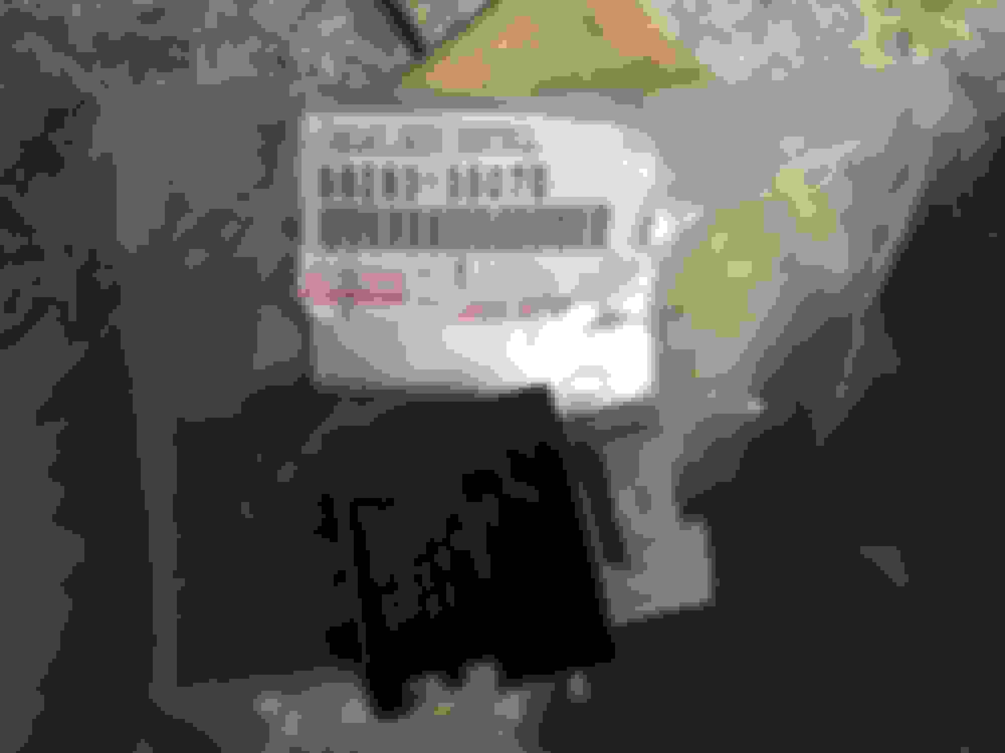
Here's a new gasket for the oxygen sensor (P/N 89466-20020-83) to be used on the EGCV after it is re-installed:
And some new nuts for the #2 turbo transition pipe and oxygen sensor:
At this point, yes the EGCV housing went back on in the TSRM order. It's just the reverse of the process I described earlier. This time you'll be using that 14mm bolt extraction socket and all the same adapter hardware with the slight angle of the wobble fitting to help you seat the socket on the brand new (!!!) nut to torque it down to the required specs.
Now it's beginning to look better in there again!
Finally, few pictures for this but once all the other turbo related parts are in place you finish it off by connecting the stock cat or downpipe. One gasket for this comes in the factory TT gasket kit. Along with it you should consider using one of Driftmotion's aftermarket gaskets to compliment the sealing in that part of the exhaust system.
Driftmotion also makes a gasket for the JDM Aristo and JDM Supra 2JZ-GTE stock twin turbo system as well. Remember that you still have to install the OEM round exhaust gasket in this location whether you get Driftmotion's gasket or not.
That's it really! The TSRM explains the rest. You pretty much have to install ALL of the upper air intake parts in the order it tells you to so that they all fit correctly.
With one exception. Before starting into any of that, reconnect the rear-most vacuum hoses onto the top metal vacuum hose assembly. Use the set of flat nose with bent end automotive hose clamp pliers for this. It will make things SO much easier just the same as it did when disassembling the system.
I cannot find a good tool to recommend like the long pliers I have but this is sort of close. But the big loop at the end will get in the way. You need to find a pair on the ends (but with a bent end) like the ones I was using.
Rewiring the fans for just like Toyota did for the Supra MKIV TT
The next thing I got into doing was to re-wire the auxiliary electric fan control system... again
When I had just the single 1993-1996 Supra MKIV TT auxiliary cooling fan installed the aftermarket Mishimoto controller was doing just fine. However once I decided to upgrade to the 1997-2002 Supra TT radiator shroud and install a Z30 Soarer front condenser A/C cooling fan onto the same 30A circuit, it wasn't holding up.
I made the wire gauges for that circuit 10-gauge from the power source, fuse and power relay but the wires going into the OEM wires going into the fans themselves were only 12-gauge from Toyota and I also suspect that the output ground wire from the Mishimoto controller is only about 12-gauge as well.
Given that I remote mounted the 30A fan power relay and fuse which added some more length to the total wire path, I think this may have been too much for the Mishimoto controller's stock wires even when all three fans together shouldn't have drawn more than 20A continuous (x2 pancake fans at 4.5A each and the larger A/C condenser fan at 8.5A).
So I decided to recreate Toyota's entire fan control system instead and put the 10 gauge 30A power feed wire and fuse much closer to the battery again just to be safe.
It's certainly not the cheapest way to control fans and annoyingly the relay bracket is discontinued and one of the connectors was discontinued forcing me to search through Toyota's terminal wire and connector TSRM to find anything that might be a close match.
In fact there was just such a connector. So I picked up two of them and it only required a Dremel to carefully remove some guide material on the outer connector casing.
85925-20010 TT fan control relay (rated for 30A)
88263-35070 TT fan power relay (that allows the fan control relay to get its power)
90980-10939 TT fan power relay connector (requires x2 82998-12480 terminals & x2 82998-12440 terminals)
90980-11304 TT fan control relay connector DISCONTINUED...
90980-10940 Alternative TT fan control relay connector, requiring only slight modification with a Dremel tool (requires x2 82998-12480 & x2 82998-12440 terminals)
89428-24010 Supra MKIV TT radiator coolant temperature "switch" (coolant sensor)
90980 -11235 Connector for the MKIV TT coolant temperature switch/sensor in radiator (uses x2 82998-12440 terminals)
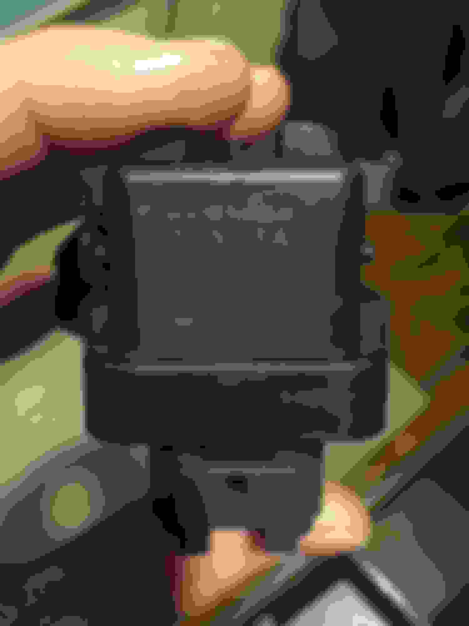
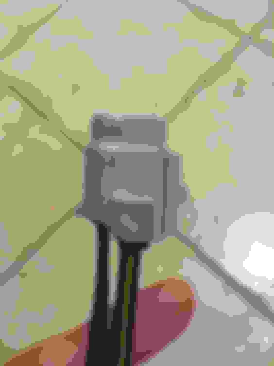
Pictured here is just the fan control relay (-20010) and the (-10940) connector before and after modification to make it fit.
After light modification with a Dremel tool it fits perfectly. The trimmed-off guides aren't necessary to keep the connector seated securely:
Now let's look at the Supra MKIV TT's fan control wiring diagram for the full 30A Fan control circuit. There is no difference between the 1993-1996 and 1997-1998(and JDM 1997-2002) fan control circuits other than that the later versions got two pancake fans behind the radiator and all twin turbo automatic models got an additional fan in front of the A/C condenser. For all MKIV TT model years the relays, fuse and fan wiring were rated for the same 30A even though all three OEM auxiliary fans combined should only pull just below 20A continuous.
And the more detailed version of the circuit from the TSRM:
As you'll see from the thread linked below, and as was kindly explained to me by SF member Bitshiftr, the way this circuit works is to use the fan power relay (it's a factory repurposed ABS traction relay) as a kind of master control that the power is drawn through and which has basically a 12V switched trigger. Then from there the power flows into the fan control relay... BUT it's a little weird. Instead of a 12V trigger signal being what turns the fans on, instead this relay keeps the fans off until something breaks the 12V trigger circuit. It operates in the inverse of a normal relay.
What breaks the fan control relay's otherwise constant 12V trigger circuit? One of two things: either the Supra TT's coolant temperature "switch" in the bottom of the radiator or the "triple pressure switch" located on the exhaust side of the engine bay right on one of the A/C lines (and guess what? The SC300/400 already has this same A/C switch as standard equipment!).
Basically: If the radiator "switch" encounters coolant over 212F it breaks the constant circuit and thus triggers the fans on, but it doesn't complete the circuit again until the coolant temperature goes down to 197F. In the same way, if you turn the A/C on and the pressure inside the A/C system reaches a certain point then that "switch" breaks the otherwise constant circuit and triggers the fans on and they will stay on until the A/C system's pressure drops to a certain level (whether you have the A/C on or just a little after you turn it off when the fans were already running).
Bitshifter described it to me as a "double-negative" circuit and it took a while for me to understand that it's possible to make a relay that can operate in the inverse of how a normal relay is triggered but once I realized that it all made sense to me.
CinePhile, your confusion is justified. This is a weird circuit. It's kindof a double negative.
Here's how I would explain it (note that this is only valid for the GTE cars...not the GE cars):
When the engine is running normally, with A/C on or off (doesn't matter), the radiator aux fans don't run. This is because both E5 (Engine Coolant Temp Switch) and A3 (A/C Single Pressure Switch) are closed (connected), which allows power to flow through the coil (pins 4-3) of "Fan Relay #1", thus cutting the power supply to the fans, which comes from pins 2-1 of "Fan Relay #1" (the normally closed contact and the common contact, respectively). This is because "Fan Relay #1" is wired in a normally closed fashion (pins 2-1 are connected only when there's no power flowing through pins 4-3).
If either E5 (Engine Coolant Temp Switch) or A3 (A/C Single Pressure Switch) open up, the coil side of "Fan Relay #1" loses power and the relay "relaxes", contacting pins 2-1 and allowing power to flow to the aux fans. Note that if either E5 or A3 open up, there's a serious problem! (the car is starting to overheat or the A/C coolant pressure is abnormal.) Toyota designed this in a failsafe way...any failure (or abnormal situation) causes the aux fans to turn on to try to cool things down.
Said another way the aux fans are defaulted to always on, unless both E5 and A3 are happy. Fortunately, both E5 and A3 are happy most of the time (under normal operating conditions). The aux fans aren't triggered on in this design...they are triggered off when an abnormal situation occcurs.
I hope that helps with your "Aha!" moment. If not, let me know and I'll try a different way of describing how it works.
Your description was perfect, Bitshiftr! I just needed to think outside the box for a moment to get it
Okay, with that being understood, here's how I began wiring it up. Now first, where to put the relays? There is hardly any good space left inside the SC's engine bay. Well, Toyota in fact had such a place for fan control relays and they used it on both the MKIV TT Supra and the Z30 Soarer:
Under the headlight on the Supra MKIV TT's. It's not extremely convenient but how often will it need to be accessed? Now how can this location be used in the SC? There's a lot of battery tray blocking things even with the headlight removed.
I think in the SC/Soarer's case they used this solution which is the route I went with: I removed the driver's side forward fender liner to access the area where the power steering cooler line is located. Above that there is a single un-used threaded location on the sheetmetal which only needs the right thread and pitch OEM bolt added to.
Great!! But this used Toyota 4Runner relay bracket/holder is only good for one relay. I have two relays that need to sit side by side. Hmm. Well in a pinch I guess I could zip-tie them together and wrap some electrical tap in the middle to keep them from slipping apart with road vibrations.
I kept them secured like that for a while but I wanted a better solution. With the MKIV TT's fan relay bracket being discontinued I needed some alternative or I'd have to make one myself.
I did find one but it proved to be hard to source initially... and a lot of Land Cruiser 100 and Lexus LX470 owners may need these. This is a very similar fan control relay but it's only rated for a 20A circuit. Yet it comes with a bracket for two relays side by side. All that would be needed is to make a custom L-shaped bracket for it to bolt into the required location in the SC's fender above the PS cooling lines.
This OEM relay & bracket carries Toyota P/N 88630-60091
But again... it's very hard to find the bracket used and I'd definitely want to make sure the relay itself got into the hands of an LC100 or LX470 owner who needed it. These were on an extended national backorder in the U.S. when I tried to buy one.
It's pretty close to being exactly what is needed.
However, I decided to make my own bracket. I got hold of another used 4Runner relay bracket so that I now had two of them.
And by now I had ordered a new 88263-35070 relay and a new 85925-20010 relay:
All right... now I just needed to make a cardboard template mockup of the bracket shape that I wanted and then all I needed to do was trace it onto some thick stainless steel scrap metal, carefully cut out the template lines with a cutoff wheel (be VERY careful when using one of these! Gloves, goggles and a healthy fear of the potentially deadly spinning blade are required!!) and then I just needed to grind off the rough areas, smooth the edges, scuff it with 100-grit sandpaper, prime it and paint it. And then drill out the appropriate holes that I had marked from my cardboard template and hammer the right bends that I needed with a vise and a hammer.
For this I used VHT 550F engine primer, VHT 250F black wheel paint and a VHT 250F gloss top coat to finish it.
I got one of the bends slightly askew but it works perfectly.
The rest of the wiring just took a couple of nights to get through.
First, before I finished up the twin turbo re-installation I installed the needed OEM radiator temperature switch (sensor) before refilling the coolant. I'd bought it new in 2013 and left it installed but never hooked it up to anything. They're kind of pricey so I figured I'd put it to good use now with a brand new connector and two terminal repair wires.
Next I had to run the wires for the A/C triple pressure switch and the ground wire for the trigger circuit. The Supra MKIV TT wiring TSRM states that the appropriate ground location for the relay trigger circuit is on the passenger side right next to the air box (or cone filter) while the appropriate ground location for the cooling fans themselves is on the driver's side front fender right next to the windshield washer fluid neck.
For the passenger side ground near the air filter I used 14ga brown wire from a marine supply store and I fitted a small ring terminal to that.
The A/C pressure switch connector has two blank plugs (save those as you can use them later on). You'll need two 82998-12440 terminals to fill them. To keep the wiring from there compact I used some 16ga wire that I had left over from a scrap SC300 Automatic wiring harness. I soldered and heat shrink tubed them to extend as needed.
After I got those wires through the factory plastic cladding running along the side of the passenger side fender I was able to switch over to standard store bought marine 16ga wire as needed to make the wire run across the front of the radiator. I used the same wiring path that I used for my Big 3 alternator cable but I kept these two wires and the 14ga brown ground wire in their own separate plastic tubing. All the plastic tubing was wrapped in Scotch Super33+ electrical tape to protect it from the elements.
From there I made sure that the 82998-12440 wires (16ga from Toyota) all had the same gauge wires connected to them. I tried my best to keep some color order with what was available from local marine supply stores. Since the grounds for both relays and the trigger circuit all lead to that passenger side front fender ground location that is why I decided to move up to a 14ga brown wire for the remainder of that circuit path.
The rest of this wiring as a lot of careful following of the circuit path in the Toyota diagrams one wire at a time and soldering and heat shrinking each connection while under the car. The wiring harness took shape from there.
Honestly... I think I could have done a much better job of it but it wasn't easy to group everything as neatly as I had hoped.
A 10ga power wire with a 30A in-line fuse feeds directly from the battery positive terminal through electrical tape wrapped conduit down behind and around the battery and through a crevice just behind the headlight. The 12V Switched trigger signal for the fan power relay follows the same location. The power wire from the fan control relay right up to the harness I made for all three fans follows the same physical path.
Here's what the custom harness looks like now completely finished and wrapped in conduit and Scotch Super33+ electrical tape.
I think it should be solid. It's a very redundantly safe circuit and I made sure all the wires were the correct gauge or a slightly too big at the heavy power draw and ground connections.
This all tucks neatly under the forward fender cover! Easy to service in the future if needed.
My only issue with it at the moment is that I think my A/C triple pressure switch may be getting tired after 29 years because initially with the A/C on the fans eventually turn on but then turn on and off just a bit while at idle... for a little while. When everything is hot in the engine bay it seems to keep the fans on normal cycles. I'm ordering a new one in case it will be needed.
Other than that I'm very happy with the operation of the fans now!
2003-2010 SC430 130A 6-phase Alternator Upgrade for the SC!
Next I dealt with my lingering issue with needing a better than stock alternator. The factory Supra TT Automatic 3-phase 100A is very reliable but just seems to be on the edge of what is needed when I use turn signals, brake lights and the cooling fans all at the same time.
I finally ordered a new/remanufactured 27060-50280-84 6-phase 130 Amp alternator for a 2003-2010 Lexus SC430 from a Lexus dealer. Usually the common upgrade for Supras and SCs is a modified Tundra or Sequoia alternator that is the 6-phase type in 130A or 150A ratings.
This is exactly the same thing but it's just 130A and has the same oval type plug that Supras and later SCs use so no re-pinning is needed.
One of the ears still had to be cut off and the area ground smooth and the alternator still needed to be mocked up on the car to get an accurate marking of exactly how many millimeters to trim from the back of one of its other ears but it was pretty straightforward. A Dewalt cutoff wheel tool with the thinnest wheel available made this easy. I have no lathe so careful eyeballing of the main cut with many very careful final passes did the job. I was able to finish off and smooth things over first with an old shop grinding wheel on my workbench and then with 100 grit sandpaper for finishing.
The amount required to be removed from the rear section of the one ear came to approximately 5mm. Seems to be consistent with what I have read in the many other threads covering this upgrade.
This time when I installed it... the voltage was very stable! Not mind-blowing, just stable, normal and with no worrying voltage drops when activating my turn signals, hazards, brake lights or when the fans came on.
For any future alternator replacements I will transfer the front of my alternator housing to the new alternator rather than cut another one all over again.
Also I did not have to do any pulley swap to make this work. I will double check the accessory tensioner marks but I don't think there should be any need to swap over a JZ alternator pulley. If there is, however then I'll take care of that pronto.
Now I'm caught up to where I am currently with my SC.
First, since my battery charging voltage with a multimeter appears to be right about 13.5V consistently now I am thinking that either my Prosport voltmeter gauge is inaccurate when it often still shows drops to 12.5V... or maybe the location that I am tapping my voltmeter wires into are just not ideal. I'll deal with that soon.
....
The other thing that I'm getting into next is to figure out why my 2nd turbo still isn't coming online (yes, still). It feels different now and it isn't giving me a death whine but I've narrowed it down to the Exhaust Gas Control Housing not fully opening up at the full transition point or the Intake Air Control Valve not opening up at full transition since it's the last stage to go in the sequential twin turbo sequence.
My hunch is on the latter:
--I pressure tested my turbo wastegates before installing the new turbochargers and they checked out as working within spec.
--I also pressure tested the EGCV housing's actuator before installing it and just the same it operated exactly as it should. The ceramic valve had no binding and I installed new gaskets.
--I pressure tested my Intake Air Control Valve actuator and it also operates smoothing in spec with my Mityvac. I have a spare brand new one of those assemblies and a new reed valve if I really need it... but the used one in my SC already had a new reed valve and new gaskets installed just a few months ago. I also tested its operation by manually pressurizing its VSV to the 7.8 PSI that the shop manual test calls for and then manually activating its VSV. That worked perfectly also and I was able to increase the Mityvac pressure up to about 10 psi where the valve is fully open... and then disconnect power to the VSV to see the valve close as it should. I think my Intake Air Control Valve and the VSV itself are fine.
--I then took out all four turbo VSVs and tested them for electrical function and pressure holding according to the shop manual procedure. All of them functioned as he should and all held and released pressure correctly. They were all brand new when I installed the engine a couple of years ago so this wasn't surprising.
--Finally, I do feel there is a slight difference in the turbo transition now with the new turbos. Before, the blown 2nd turbo couldn't wait to whine it was dead. Now it sounds healthy but still choked once the fourth stage of the sequential process is supposed to happen around 4200RPM (when the Intake Air Control Valve is supposed to open up).
Now I recall something that should have stood out to me when I first had to correct my coil pack wiring after initially starting the engine in 2018. The Intake Air Control VSV wiring is right up there alongside the TT coil pack wiring and I did have some confusion about making sure those wires were set right.
The guy who messed with that engine harness before I got into it did some really bad repairs and I think this may have been part of it.
So my theory right now is that if I test each +12V and ECU ground wire for each turbo VSV connector I will probably find that three of the VSVs are getting their proper connections and signals.... but I suspect that I will find something wrong when I test that Intake Air Control Valve VSV connector. It represents the last stage in the sequential turbo process and what is happening would make sense if it turns out that its VSV hasn't even been activating all this time.
It's been raining a lot for days and I haven't been able to get dry time to go through any of this and verify it back to the ECU's pins for each VSV. Soon hopefully.
First, here is Albon's excellent video explaining exactly how each stage in the MKIV Supra sequential twin turbo system works
(Starting at time marker 1min, 52sec. For just the blow by blow of each stage's operation as RPM increases, skip to time marker 2min, 48sec).
It's the same for VVT-i but do note that he is demonstrating with the USDM/UK/Euro/Export version of the system which has some physical differences. The operation is pretty much the same for all, however:
I was able to test the +12V pins of each of the four turbo VSV connectors with my multimeter. All four of them checked out OK.
With better weather verifying continuity between all four connector Pin-2 locations with their corresponding pins on the ECU �B� connector is next.
If all those check out OK... then I�ll need a new theory as to what isn�t functioning correctly.
Further Edit/Update 6/26/2021:
The weather finally cleared up and I removed the ECU, got to the harness' ECU "B" connector and continuity tested each of the four turbo VSVs at their Pin-2 locations against each corresponding pin at the ECU "B" connector. All of them checked out with good continuity.
Then I unwrapped the part of the engine harness from the Intake Air Control Valve and Wastegate VSV connectors all the way down to where the cam gears are to check all my wiring repairs from 2018. There were no incorrect splices there... so wires indeed were following their correct paths. I re-wrapped that part of the harness and put everything back.
This is a good thing... but it unfortunately has shot down my theory that something may have been wrong with one or more wires going to one of the turbo VSVs. Nope, all the wiring is fine and all four of those VSVs were installed brand new in 2018 and they all pass electrical and pressure hold/release tests.
...
Therefore the malfunction with turbo #2 (which is a new rebuilt assembly now) not transitioning correctly has to be something else (Edit: This turned out to be a blocked metal pressure line on top of the twin turbo assembly allowing NO pressure at all to reach the EGCV VSV).
Last edited by KahnBB6; 06-29-21 at 04:30 AM.
Reason: Updated info
Attached at the bottom of this post is a PDF of the full description of how each stage in the 2JZ-GTE sequential twin turbo system works. This was originally from the www.max-boost.co.uk website but sadly it has gone offline now.
HUGE update here Craig! I'm so impressed with how thorough you are and how well documented your car has been from the start. It looks stunning and I hope you're pleased with the awesome progress you've made. This thing is sick!
Thanks Rudy! I haven�t done any proper picture-filled DIY posts lately and I hope those last few, especially covering the hard parts of the twin turbo system removal and reinstallation, are helpful to anyone in the same situation.
I think I�m very close now to working out the last couple of lingering drivability issues. Fingers crossed!
As for �beautiful�, haha I appreciate it! But my SC is long overdue for a full repaint. I have to hold out longer for that.
With it getting closer to fully sorted out I should take some pictures of it. This thread is all technical info and no beauty shots
Craig, it is beautiful! My car needs a respray desperately, however, I remind myself of the age of these now and try to give it some credit. Plus, I know if I ever painted mine I'd never want to take it anywhere or park it in lots with other cars any more lol. Keep it up and enjoy that bad boy!!
What knowledge, ask me if I have learned a lot, my brain is so swollen, don't know if it will ever be normal again.
Haha! I hope it was interesting and informative, Bill!
It's an ingenious system for its time that provides a great stock powerband with excellent low end torque that pre-dated variable valve timing (which was incorporated into a later revision of the 2JZ-GTE) and much better and more modern turbocharger technology.
Now if I could only get that 2nd turbo transition working right for once!
I hope things are going well with your SC!
Originally Posted by RudysSC
haha Bill!!
Craig, it is beautiful! My car needs a respray desperately, however, I remind myself of the age of these now and try to give it some credit. Plus, I know if I ever painted mine I'd never want to take it anywhere or park it in lots with other cars any more lol. Keep it up and enjoy that bad boy!!
To me your car looks great in the pictures, Rudy!! But yes we can cut our cars some slack given their age. On the whole though the stock paint jobs usually have held up for all this time and the sheetmetal of the bodies are galvanized steel with plenty of coatings before the original clearcoat.
Personally I'm careful when I feel I need to be careful but I'm not afraid to park my car in parking lots. These vehicles should be used and enjoyed
The exception is that there are some places with very narrow compact parking spots that are probably about the same dimensions as many tight parking spaces in Japan. Even though the SC doors and hinges were designed for these tight spaces it's those times when you and everyone else is in a rush that a parking lot scratch or ding can happen.
I will keep it up, Rudy! Thanks! I can't wait to see more of your SC and Cressida!
....
As of this morning I ruled out my theory about the turbo VSV wiring being my issue (see my post just back a bit with the more recent updates). All of that checked out fine. That being the case it has to be some other reason as to why my ECGV or Intake Air Control Valve isn't fully opening... and is thus keeping the 2nd turbo from fully boosting.
Even though my Intake Air Control Valve and its VSV all operate correctly I could install the brand new one that I have. I just don't see a reason to when the one in the car tests OK.
My TT pressure tank was a brand new part when I assembled my engine but I'll test that next just to be sure it's okay. And I'm beginning to go over all of the vacuum lines that I can find in the entire system. None of that should be compromised or routed incorrectly but that's the next logical thing to rule out.
In the meantime I'm taking a break from the diagnosis to give the SC some road time again
I cannot fully express what a feeling it was when I found my "eureka!" that finally solved this issue. I now know that this is primarily what was causing the sequential turbo #2 transition issue.
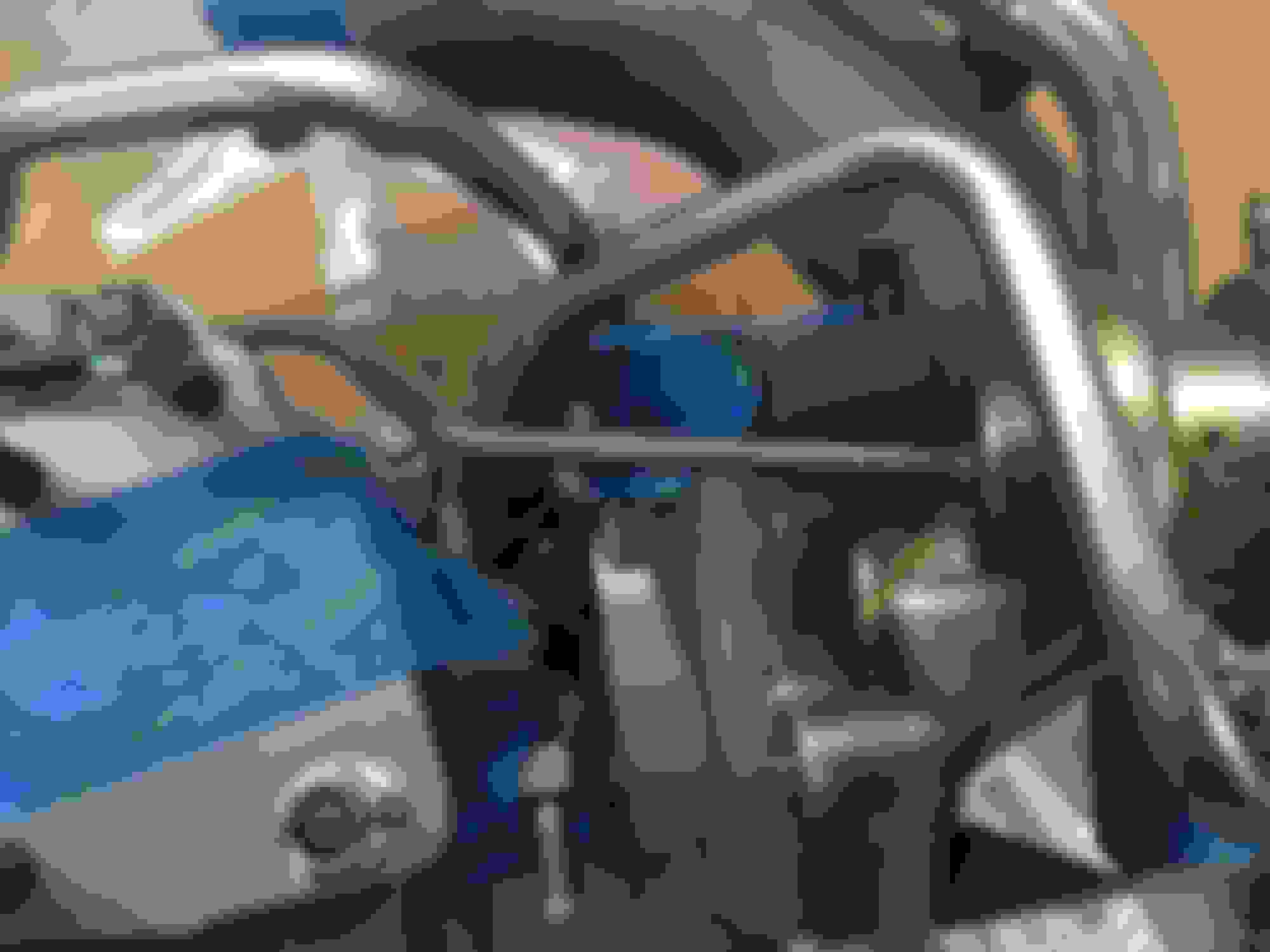
By feel with my hand only I popped off the TT pressure tank's "B" port vacuum line (using my spare 2JZ-GTE pressure tank as a visual reference to make sure I had the correct hose) and connected my MityVac hand pump to that and set it to "pressure". I was then able to simulate pressure buildup to the Intake Air Control Valve VSV and actuator and to the Exhaust Gas Control Valve VSV and actuator (since they share this same pressure source to be able to operate).
This is different from my previous tests to the VSVs and both actuators directly which I had already confirmed to work. This was a test of the full pressure path from the TT pressure tank right to those VSVs.
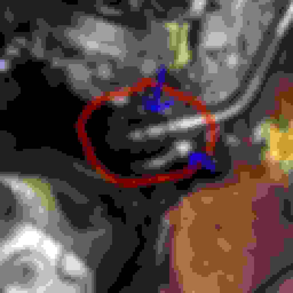
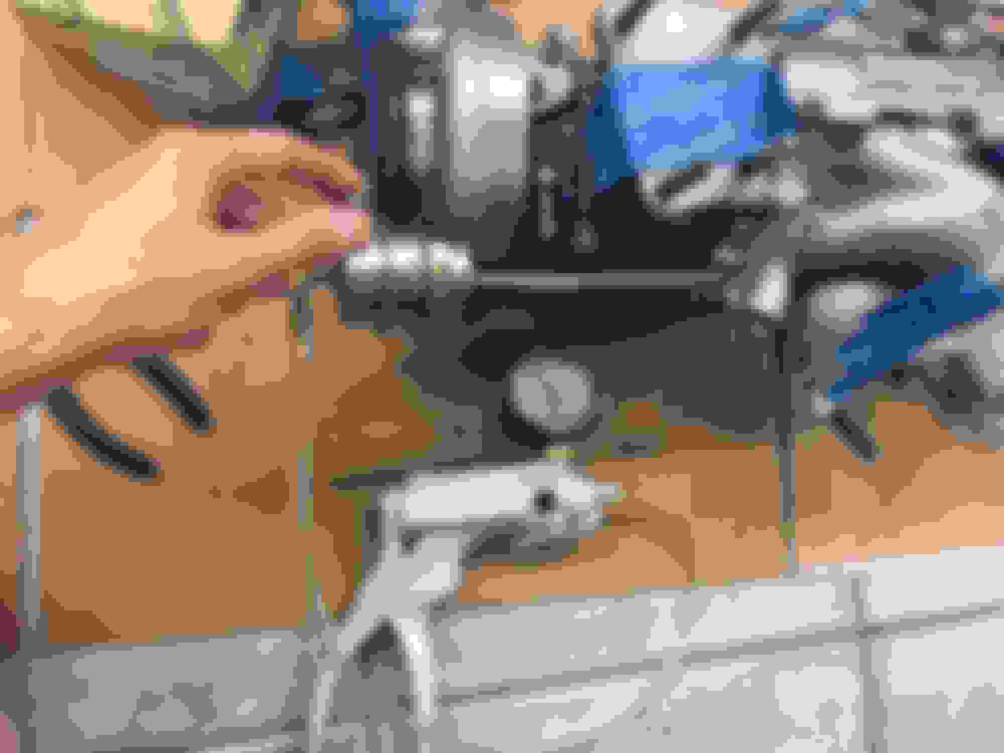
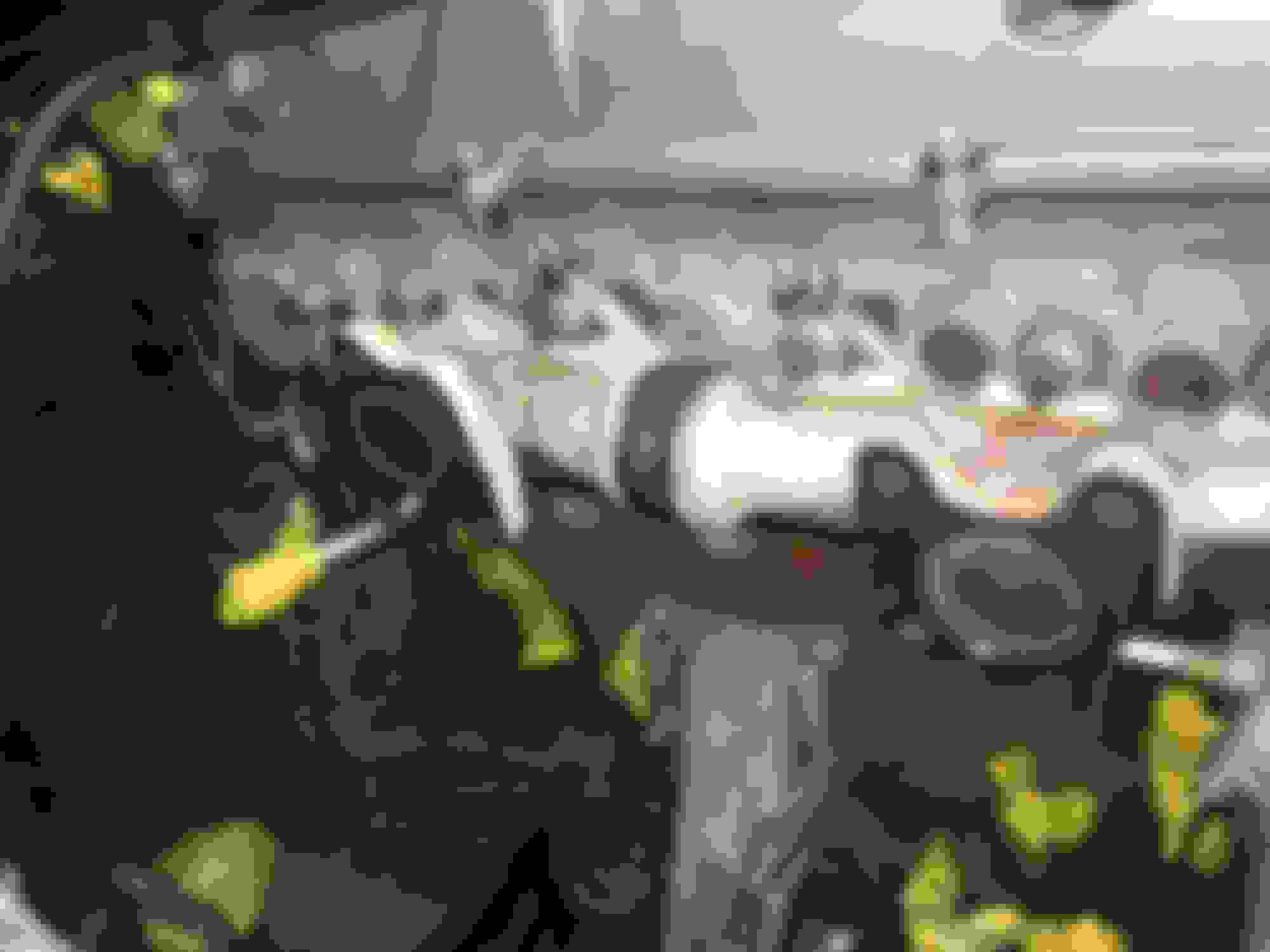
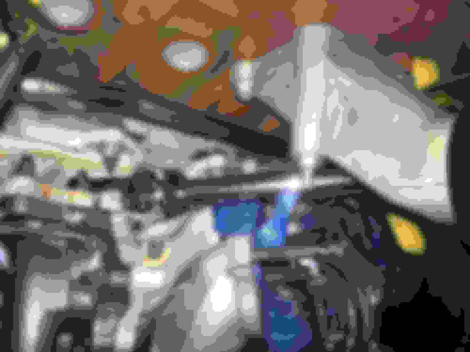
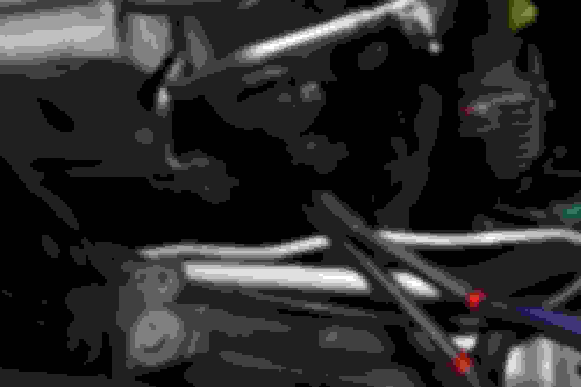
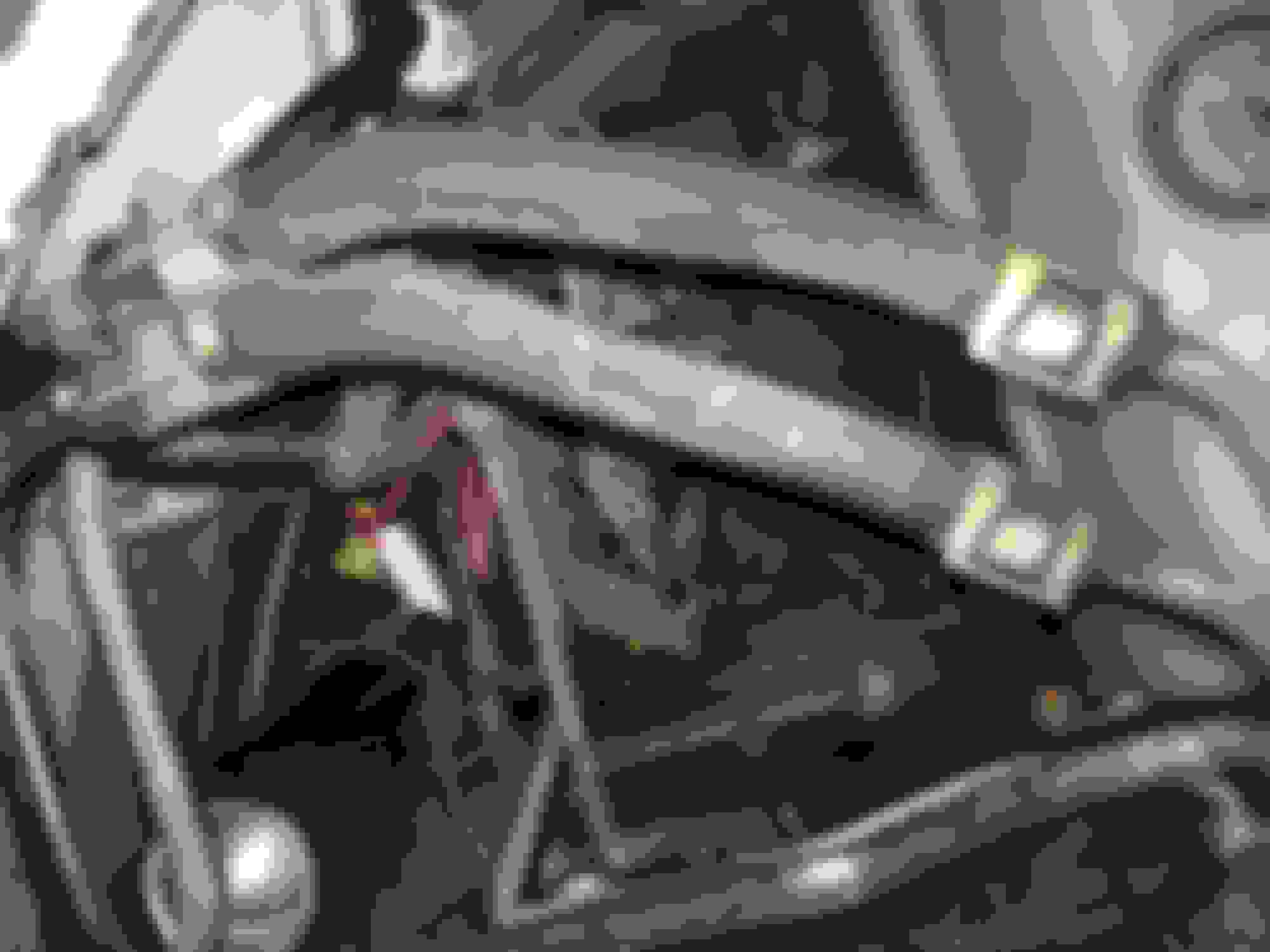
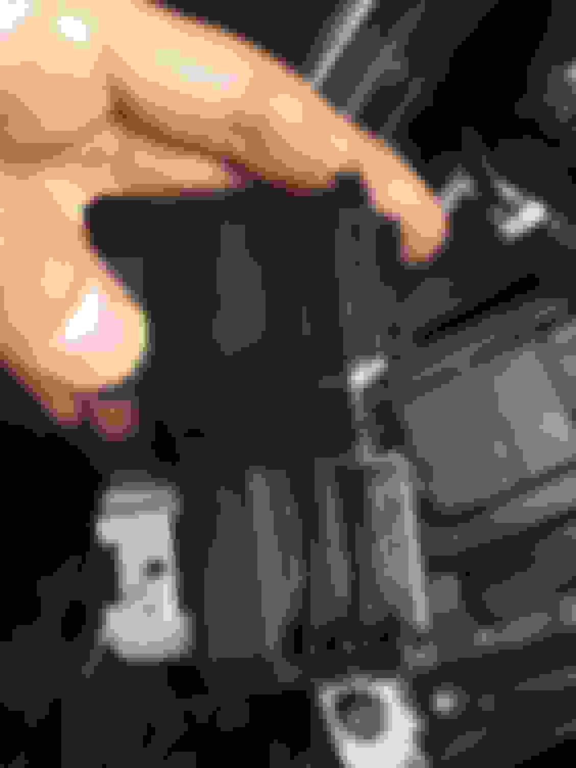
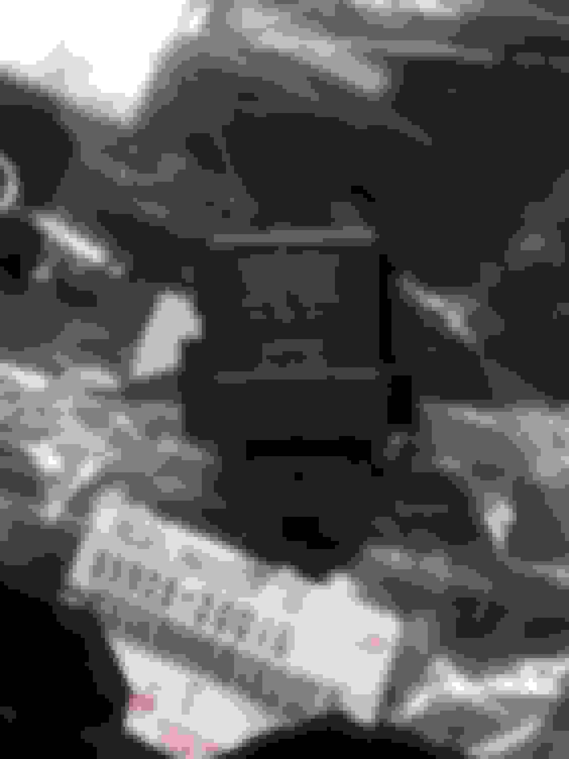
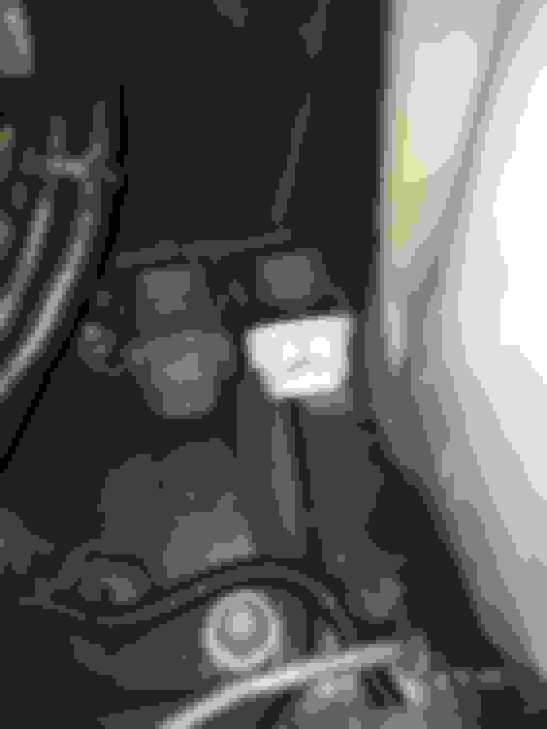
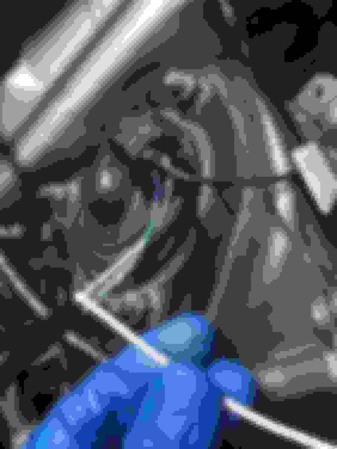
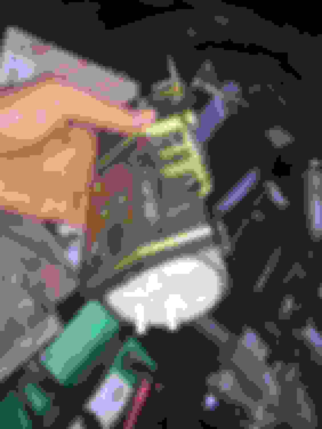
Then I got out my video boroscope tool (the red thing in the picture below) and got it down behind the Intake Air Control Valve to verify that the rubber lines back there were intact and indeed routed correctly (they were).
And lo and behold I did find an anomaly!
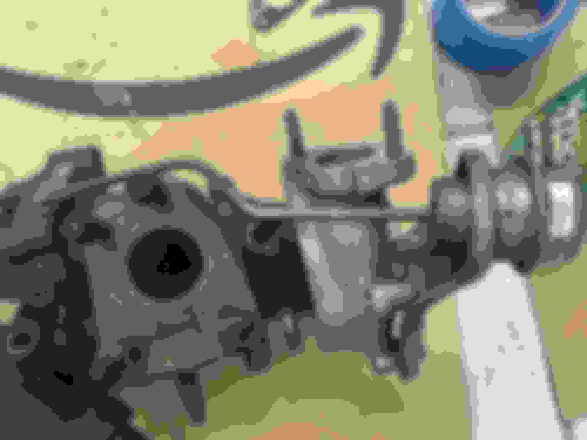
The Intake Air Control Valve VSV and actuator got correct pressure.... but the EGCV VSV and actuator did not. Somewhere inside those steel tubes that sit on top of the sequential twin turbo system through which the pressure had to pass by the Intake Air Control Valve VSV's connector there was ZERO PRESSURE getting to the EGCV VSV. That part of the metal line is internally blocked.
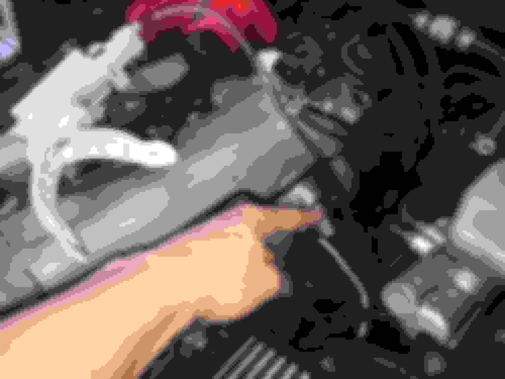
In the picture below I am pointing to the left and smaller of the two metal lines. The left one is the pressure line that feeds to the EGCV VSV's inlet port. (The one on the right feeds to the Wastegate VSV's inlet port).
BINGO!!!
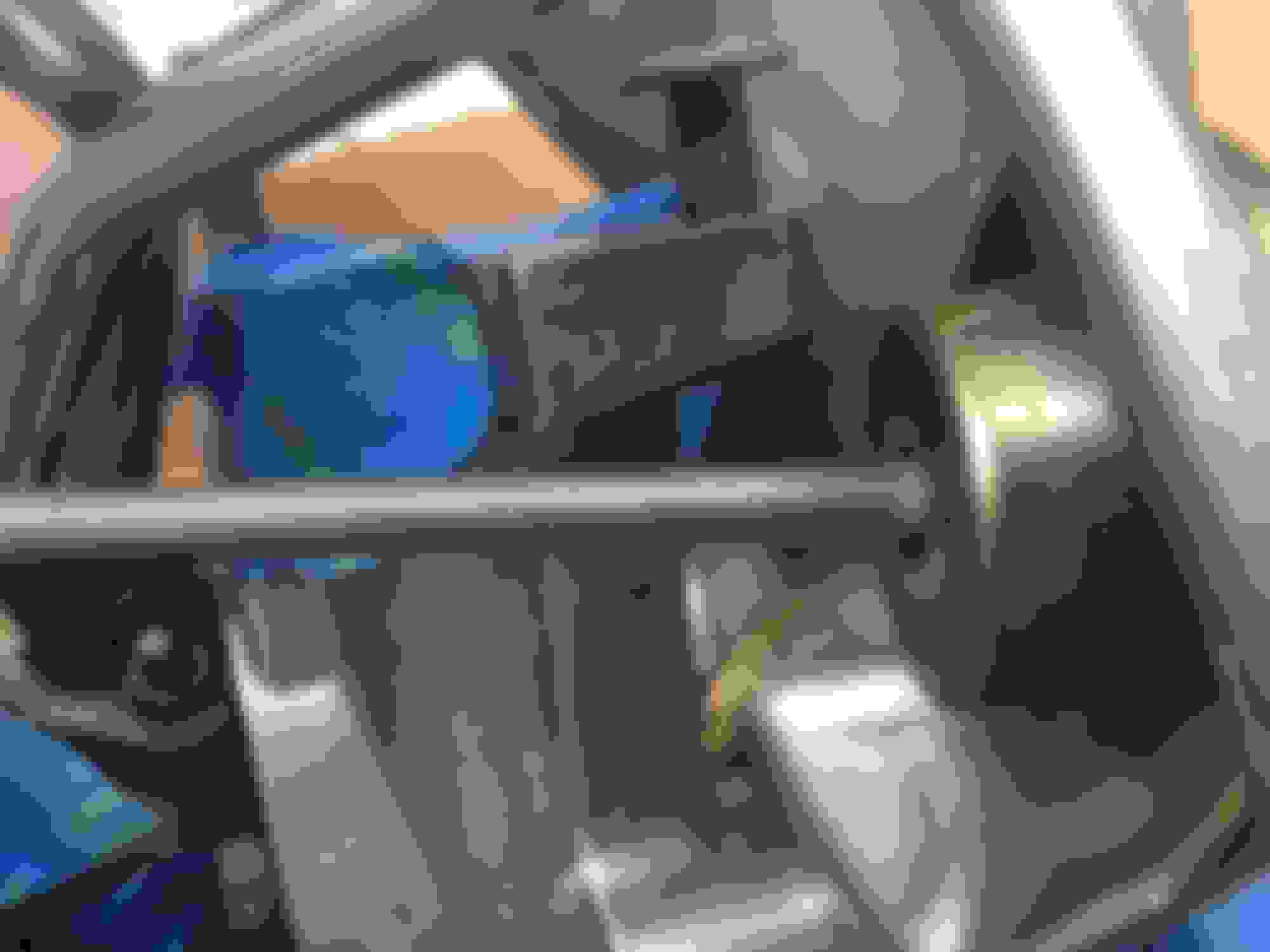
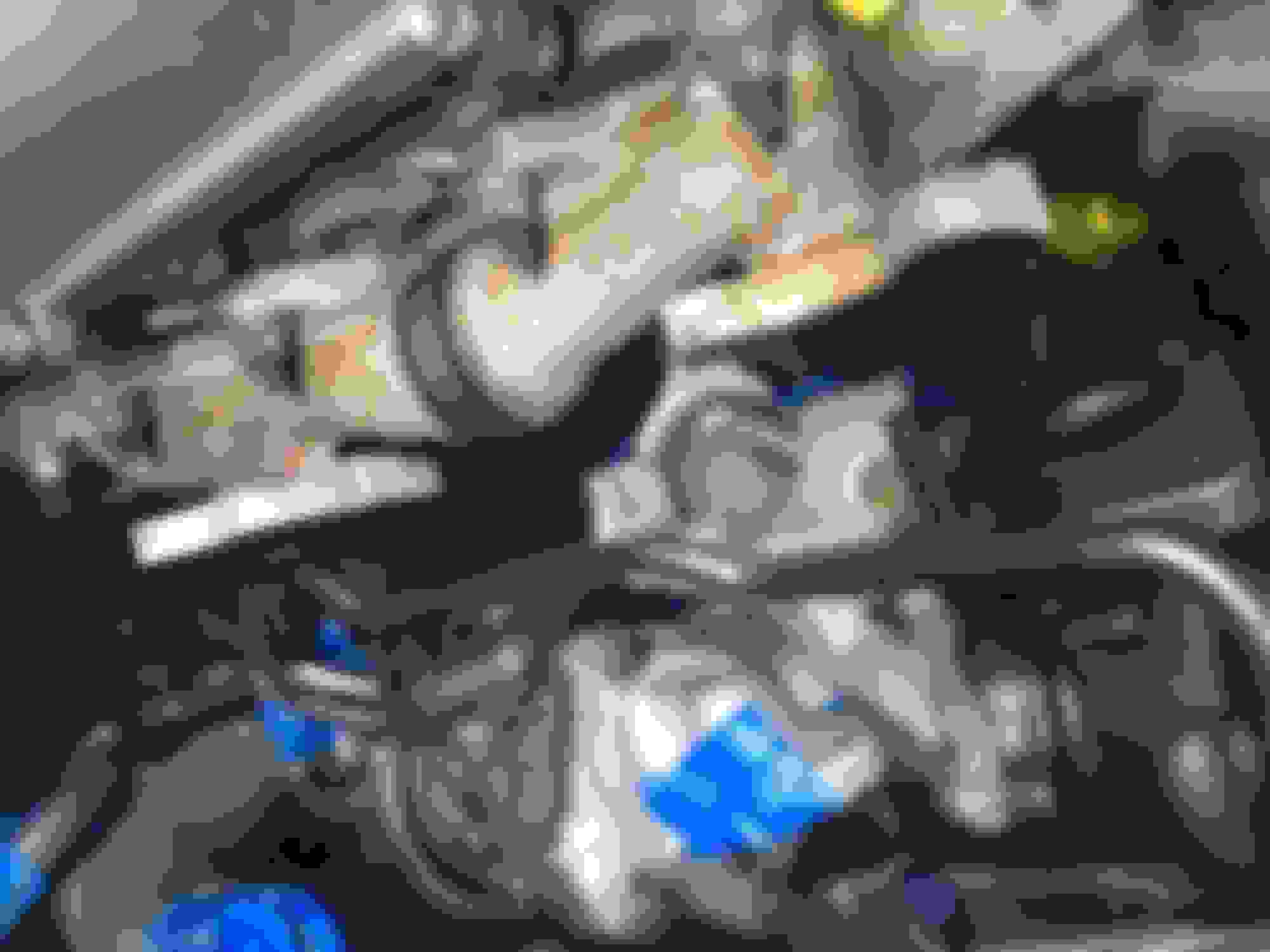
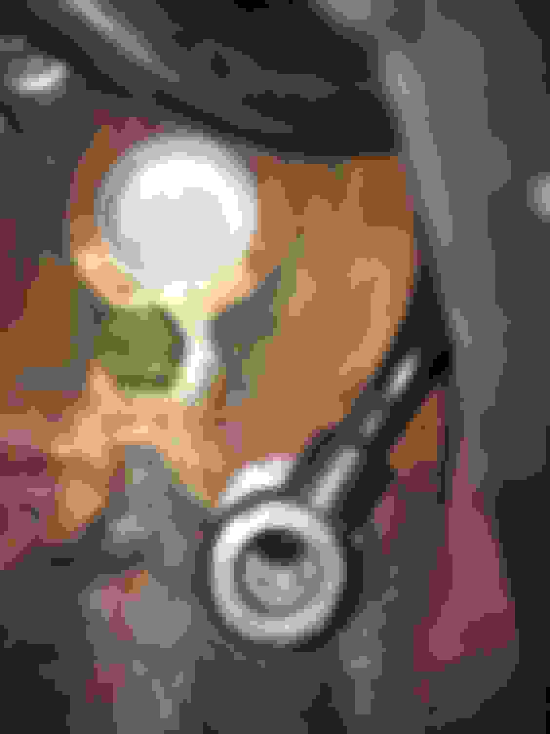
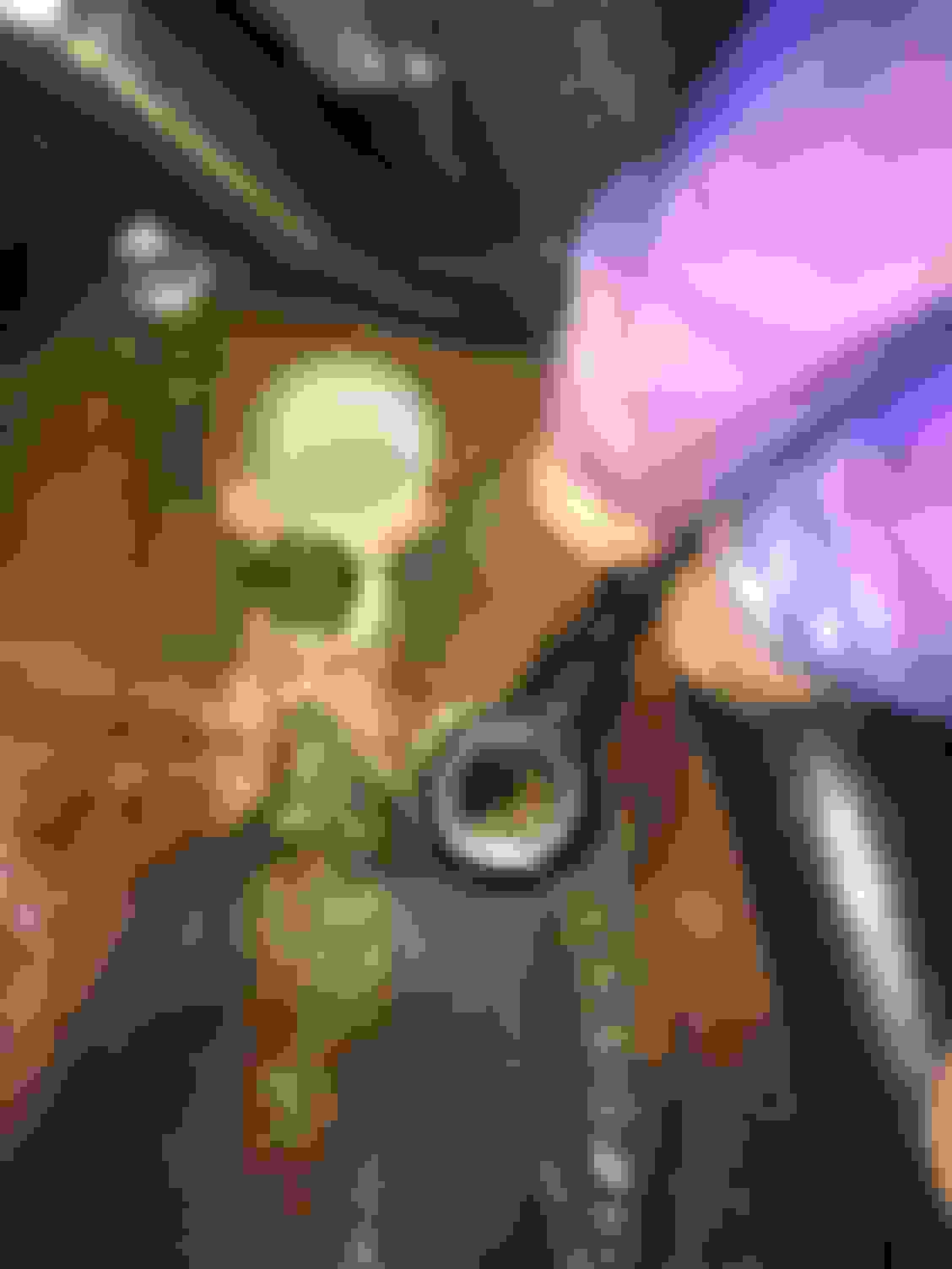
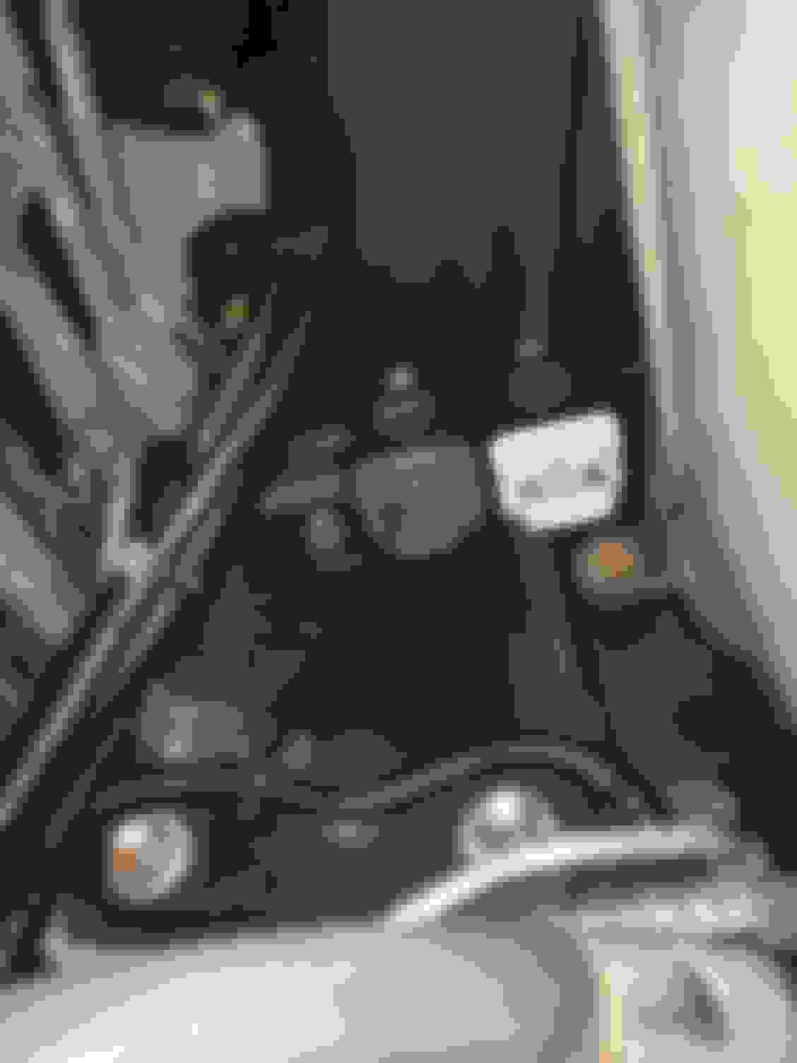
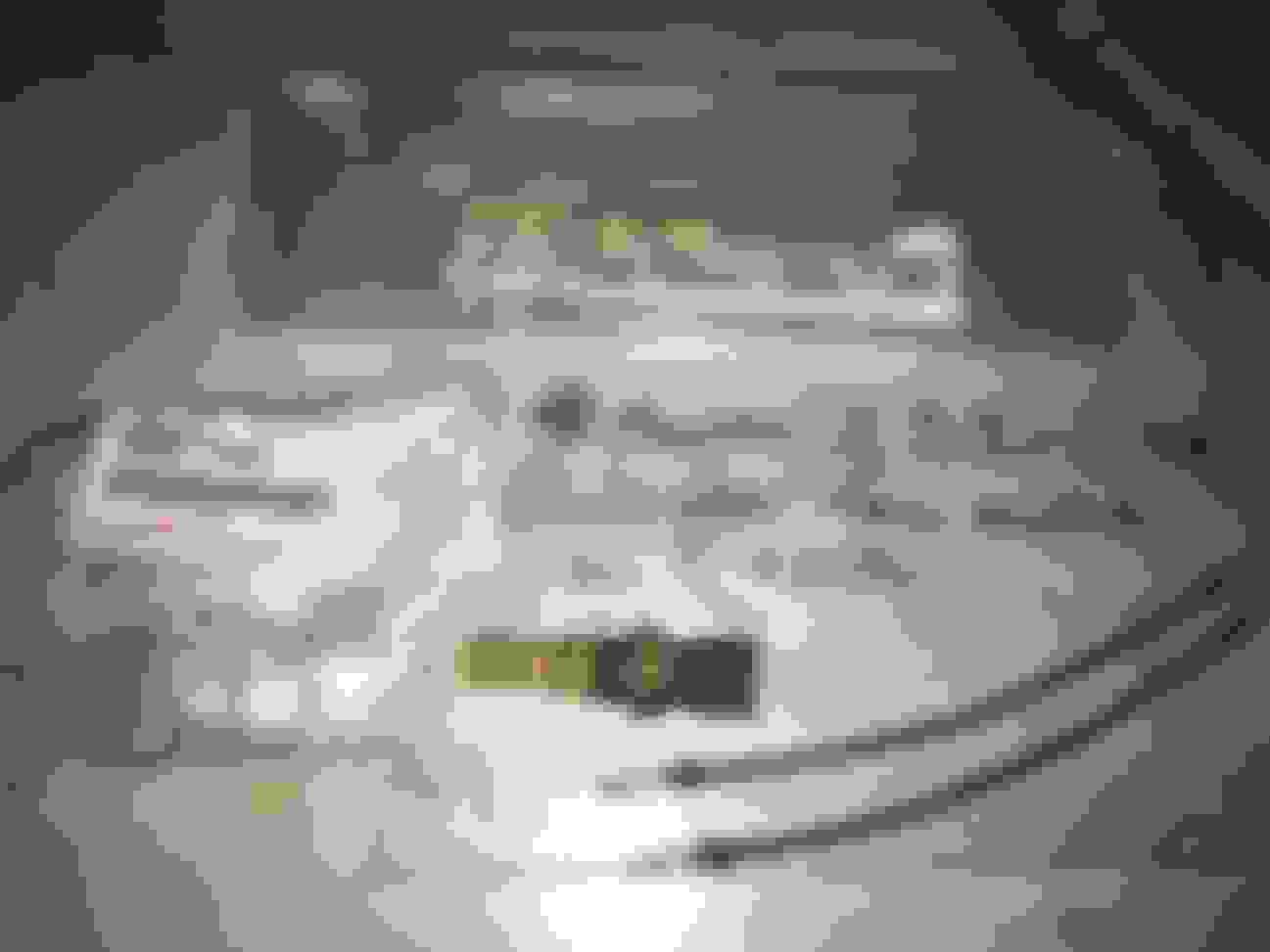
Now I had to make up a bypass for that section of the line to see if I could get both actuators and their respective VSVs fed with pressure for the TT pressure tank. I took a spool of Gates vacuum hose line that I keep handy, some scissors and a spare Toyota OEM vacuum splitter metal fitting that I had as well. I was able to use the TT pressure tank's pressure source right AT the factory location for the Intake Air Control Valve VSV's rubber line for pressure... and I added my splitter and long vacuum hose bypass line there.
I then fed that bypass vacuum line directly into the EGCV actuator. I did the same direct connection to the (turbo)IACV actuator.
......
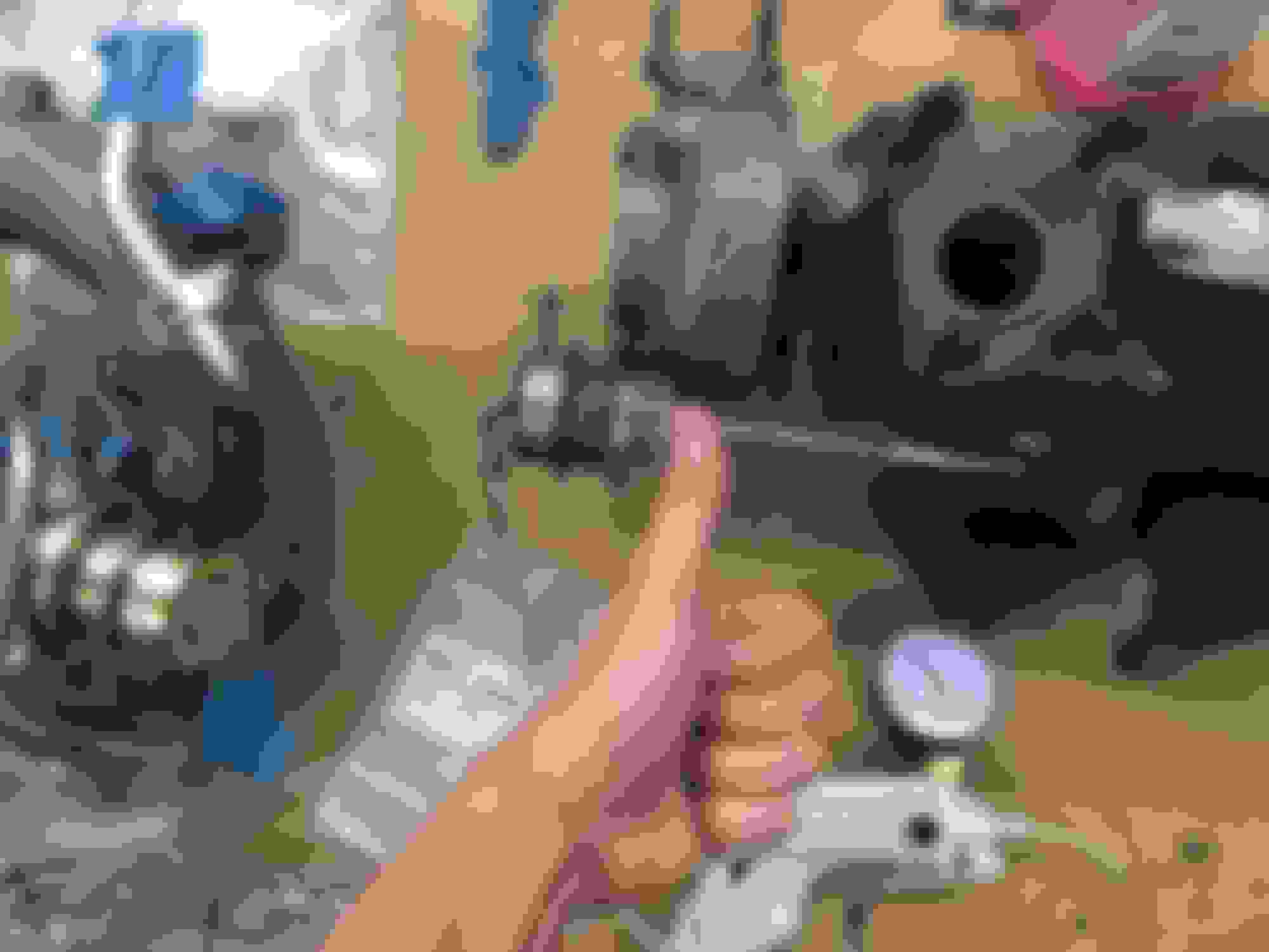
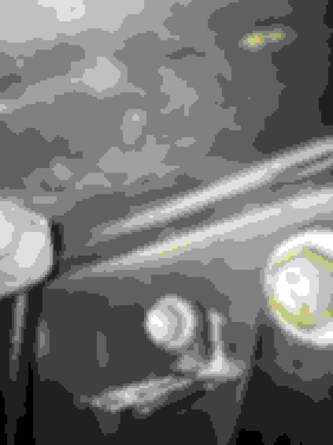
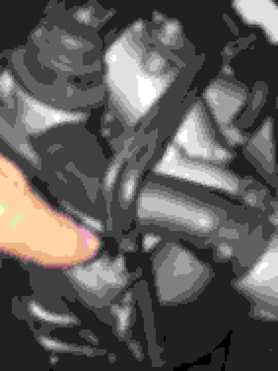
In the picture below I am touching my very long temporary bypass hose for the EGCV VSV that comes from the temporary pressure line splitter above right at the (turbo)IACV VSV's feed from the metal hard lines.
Later I will have to remove the metal line assembly and use shop air to blow out the blocked tube (and every tube on it for good measure).
Again I simulated the TT pressure tank's pressure feed of 7.8 PSI with my Mityvac hand pump and now BOTH actuators moved with pressure built up and applied and BOTH released when hitting the hand pump pressure release trigger.
I tidied everything up, routed both actuators and VSVs correctly, reconnected the TT pressure tank's "B" port hose, closed the hood, started up, warmed up with a nice drive down the road and once the coolant and oil were up to temperature I gave the car some real gas from a stoplight.
I got into the turbo transition and this time I finally experienced that infamous 1993-1995 Supra OBD1 "torque dip"... and then the damn 2nd turbocharger came online and gave that second big rush of power I had heard so much about but had never once experienced until last night.
Holy cow... it felt amazing! The bloody sequential system finally works! Sure, it's only some 310whp or so (as most 100% stock Supra TT's tend to put out on a dyno at stock boost) but it's fantastic to get the first turbo punch and then rush into yet another punch when accelerating. Not having to short shift any more is great!
......
After three years trying to figure this issue out it all came down to a clogged metal line. I never suspected this but this last week I did read about it in an all nighter search research marathon on 2nd turbo transition issues on SupraForums. Someone there very briefly mentioned that those metal lines on top of the turbocharger assembly can become clogged sometimes... and that turned out to be my problem all along.
That being said, I don't really mind having �new� rebuilt turbochargers in the car. They're good peace of mind at this point.
Now I will need to get the lines off sometime soon and blast them all out with some shop air so that I can do away with my temporary bypass line. And I need to double check the EBV metal lines to make sure that THEY have no internal clogs since they affect the pre-spool of turbo #2 to ensure that it doesn't get instantly slammed on (but I think those are fine).
I need some sleep now after that all-nighter but man am I happy to have this solved at long last!

 06-22-21, 05:10 PM


 This was like a light bulb going off for me! Brilliant solution to a very annoying problem (thank you Beezupra!)