When you click on links to various merchants on this site and make a purchase, this can result in this site earning a commission. Affiliate programs and affiliations include, but are not limited to, the eBay Partner Network.
Well, in the end, I hope you received what you paid for AND it is the perfect application for its usage. Odd that they just toss in different internals when needed and use a generic box causing all sorts of questions. But it sounds like they've been responsive and helpful.
Ha! Me too! Me too! To your point; now I must know so it will be opened before it goes in. Likely sooner than later.
I can see how this happens tho; expensive inventory and it must be turned. They certainly could have done a better job in the labeling department!
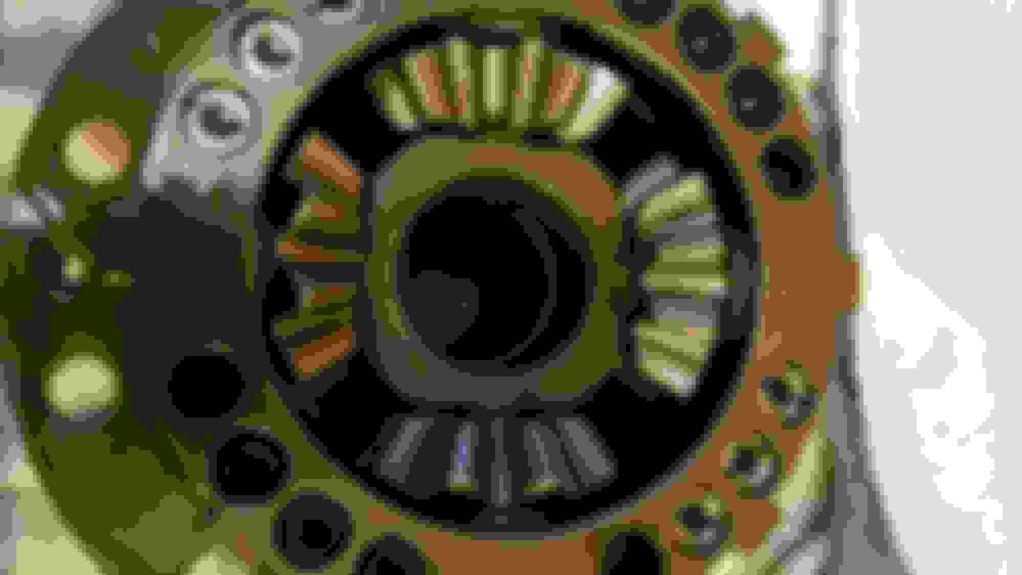
OK, I opened it and inspected the innards. All is as documented with 16 plates for maximum surface area as none are deactivated by mating like plates. Here, it is about surface area and oil control so, other than the way the discs are locked (external = drive & internal = driven), they are all the same. Oil channels on one side and flat on the other.
One observation is that they ran an oil channeled driven plate directly to the surface of the pressure ring (inner locking mechanism with the 4 pinions) and the springs. See below.
As seen from pulling the cover off.
Steel on steel oil control disks, no fiber to degrade. Exterior tabs are drive plates. Interior splines are driven plates.
Flip the ^^ above stack and place it here vv. This is a wearing surface that I would not have used personally. Shown is 4 pinion spider gears inside the pressure ring. 12 of the 16 holes have springs and the cam timing is marked 25/35 on pinion gear shaft assembly.
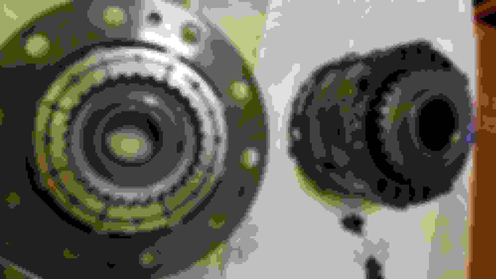
I didn't open the pressure ring assembly. It has 12 springs in this application. Supposedly there are 3 different spring rates; 18kg, 28kg, and 38kg. Think in terms of less hold-off pressure applied would make the lock action apply quicker while stiffer springs will provide smoothest lock action and the softest spring would provide the most aggressive lock. Same is true of the higher quantity 16 vs 12. That said, the little V6 is not delivering 500hp so a line must be drawn that enables the cam assembly to lock on lighter power loads.
Pressure Ring Assembly with side gear in place:
Is the "12S" indicating the pressure ring has 12 springs?
At the bottom of the picture is a Belleville conical spring atop the disk pack. Reading finds there are 3 different cone springs available; 1.4mm, 1.6mm and 1.8mm. I wish I'd measured this when it was apart just so we know. The thicker the spring, the more preload is applied to the clutch packs. The stiffer the cone spring, the higher initial breakaway torque will be and the more the car will want to understeer off throttle or part-throttle.
Re-assembly is pretty simple. There are 4 bolts at low tension securing the unit together. Basically drop everything into the cover in the reverse order; cone spring, side gears, 8 plates, the pressure ring mechanism, 8 more plates, the side gear and the Belleville cone spring. Now drop on the other half and start a couple of bolts to draw the assembly together. It took many criss cross steps with the four bolts to compress the cone springs.
That's about it. Now to get it in the car....
Last edited by 2013FSport; 12-31-19 at 10:33 AM.
Reason: Terminology and springs
Great pics of the "tear-down" there! I assume they have good QC and no burrs or scrap metal shavings were present anywhere within the unit?
Yes, everything seemed to be on the up as far as sharp edges, casting flash, debris etc, a clean process leaving no stressers to start cracks on any of the components. One thing I could not see without disassembly of the spring pack was if the spider gears had washers under them. It was was not obvious if the design had them in place or not. I only bring this up as all of them spun with a ratchet like click click click. Now that it has clutch pack, the spiders won't be seeing the action the OEM 2 pinion spider gears did.
From the IS-F forum it seems a few tried to pull the rear diff without undoing the suspension and there are mixed results. That is, some tried, some succeeded, and some failed. The thread is here https://www.clublexus.com/forums/is-...or-not-11.html Worst case is one jabs the new seal on the way back in halting forward progress and ends up ordering a new seal, replacing it, and pulling at least one side apart to minimize risk of seal damage.
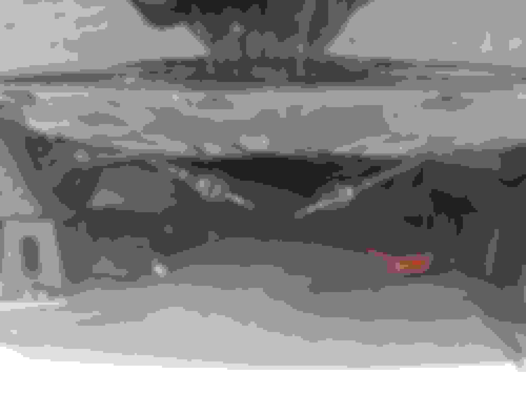
In this picture if you look at the angles of the the axle while the suspension is loaded, you notice it is nearly parallel to the ground. That said, the arc the axles travel appears to be in our favor. How you ask? When the suspension hangs down, the rear wheels get closer together, as this happens, usable range of motion is used up locking the axles in the diff. When the Diff is lowered and turned, to either side, one should be able to free an axle at a time, allowing the diff out without suspension tear down. That will be the first attempt with the car sitting on its own weight. Of course on the way back in this could make new problems as the LSD may need broke free to allow the axle splines to rotate and engage when stabbing. Time will tell. lol
Another way to look at this is with the wheels hanging down, the rear diff will need to get lower and lower to free itself, so I believe, at ride height could be in our favor.
If need be, here are some torque specs, but I think we just have a couple of braces to remove and install and it should come out.
I was able to remove the diff on my ISF without unbolting the suspension, I actually
did it two times, once for FIGS bushings and then again to install a Torsen diff.
I did it on jack stands, with a floor jack to support the diff. The axles unseat easily
with a pry bar. It would be extremely helpful to have a second set of hands to help, but
its doable on your own, just more time consuming.
Thanks for the insight. I was pretty sure it could be done. I've done hundreds of transmissions, FWD, RWD, AWD, with and without a transfercase attached. It should be a piece of cake.
You install the torsen in an existing housing or swap the whole shabang in?
With your previous experience you will have no problems, the hardest part was replacing the subframe
and pinion bushings with the FIGS poly bushings, getting the old ones out was the most time consuming
part... I installed the complete torsen diff from a 2011 ISF, works much better than the open diff. The Giken
should feel night and day different, you will be happy with the results I'm sure. I look forward to your feedback
once you have it installed. Good luck
I'm late to the game, but yes, all I needed to do was remove those two braces you picture (one each side), and then put my tire tool against the rusty ring closest to the axle shaft seal (not the sheet metal part, you'll see it, that'll bend) and leverage it straight out. Notice at the very tips of the axles, the splines have an interrupt cut in them? that's just a wire ring retaining them. Once you pull past that ring's groove, the splined shaft comes right out. Try not to put your sternum directly below the diff when you pop it off, it's worse than any medic'll give you.
I'm late to the game, but yes, all I needed to do was remove those two braces you picture (one each side), and then put my tire tool against the rusty ring closest to the axle shaft seal (not the sheet metal part, you'll see it, that'll bend) and leverage it straight out. Notice at the very tips of the axles, the splines have an interrupt cut in them? that's just a wire ring retaining them. Once you pull past that ring's groove, the splined shaft comes right out. Try not to put your sternum directly below the diff when you pop it off, it's worse than any medic'll give you.
So no need for an alignment? Just remove the subframe braces, and C clip retainers? I'm letting my uncle do this at his workplace. I'd rather have it on a lift. The less I have to pay the better.
Nope. Only fasteners I disturbed (remember, I'm going -250 to FR-S, but I can't imagine it's any different), were those braces, the 2 diff snout fasteners, the three on the back of the diff cover, and the driveshaft flange bolts. I think it was 3 different sockets and the big ol' allen you see bottom left, against the ramp. No e-clips or anything, the wire retainers are up inside the carrier, you just have to pull on the shaft right to defeat them.
I could swap back to the factory diff in less than a half hour now that I know what's what.
Yeah I'm going FR-S myself pretty soon. Just still searching for a good one. Hopefully it's not trashed by some teenager doing donuts. My uncle does differentials and what not at his work place. They build custom rock crawlers, and half mechanic shop. So once he's in there I'm sure he'll see what needs to he done. The bad thing is that he hates Japanese cars. He's a Chevy guy so when I ask why all I see is Chevy, and Fords, Dodge in the lot broken. The Yoda land cruisers, Jeeps, Buggies are getting upgraded in the bays I have to hear it lol.
Yeah I'm going FR-S myself pretty soon. Just still searching for a good one. Hopefully it's not trashed by some teenager doing donuts. My uncle does differentials and what not at his work place. They build custom rock crawlers, and half mechanic shop. So once he's in there I'm sure he'll see what needs to he done. The bad thing is that he hates Japanese cars. He's a Chevy guy so when I ask why all I see is Chevy, and Fords, Dodge in the lot broken. The Yoda land cruisers, Jeeps, Buggies are getting upgraded in the bays I have to hear it lol.
^^ I know the look. lol I was Ford guy forever as was my father. Well, other than Corvair powered sandrails we made back in the day. There will never be Dodge or Jeep in my driveway but a Mustang or Camaro is not out of the question. Anyway, not my first rodeo pulling axles as I've been doing side jobs throughout the years before and after spending six years at AAMCO transmissions. I asked the question as it, it looks like it should come free by simply dropping the main bolts that attach it. That said, although it only weighs 45/55 pounds or something, I'll try not to bounce it off my head or chest!
AXLE REMOVAL: The problem with using just one big pry bar is that torques the axle sideways which buries the wire keeper in the groove in the side gear, LOCKING THE AXLE IN PLACE and the wire keeper sometimes gets mangled. TWO LARGE SCREW DRIVERS placed 180 degrees apart and a quick pop keeps the axles centered, the wire centered, the keeper compresses and the axle pops right out with very little force and no damage to the dust shield.
Another mistake some make is trying to pop both axles free at the same time. Just do one, tie it out of the way and do the other.
BUSHINGS: Sure I've air chiseled them out of plenty of components. What I am going to try is to split the shell so it collapses on itself and falls out. The goal being to drill through the outer casing. And honestly even if I drill and leave a groove through the cast housing it won't hurt a thing. Once the shell is cut on the perimeter, the bushings literally falls out. It should be a fun few days! haha!
These bushings will be getting installed too. Hopefully this will stop or minimize wheel hop and the infamous clunk when shifting from drive to reverse.... The funny thing is they shipped them with a bunch of lube and literally nothing is moving anywhere so it seems pretty pointless to pack it in so it can ooze out on the hot days. It's not an A-Arm in motion....
GL finding a donor Torsen. I finally gave up trying to find a late model casting like mine with the same miles on it. On the 350 there are 3 different revisions to the case and innards. But they all remain functionally interchangeable.
@redspencer C, if you compare the BMW clutch plates (post 134) to our TY391 unit (post 137), you see the available quantity is based more upon available space. So the words used, "holds up to 28 plates" blah blah blah is application specific based upon the physical space available between the LSD carrier bearings to actually fit more plates. Our diff being as compact as it is, has limited space.
It seems they could have clarified their own build documents a little better too. The BMW unit lists out as 28 plates and has 28 plates. My TY391 documents read; LSD TCD 25/38-336-8-12S, yet is has 16 plates total while the build paper says "8". So, it seems strange they did not maintain the same terminology.
Another observation is that the conical spring is applying pressure over a very small surface area of that first plate on both sides of the stack. Notice that plate is clocked externally so it does not spin with the axle. I will lay odds that first plate will be the first to deform and make metal once it warps against the next internally clocked plate. Again, looking at the BMW stack they disabled part of the pack by stacking like plates together which when done under that pressure spring is a good thing.
While I'm on my rant, you also see they ran a plate over the center locking section. What I find odd here is they are using the center section as a wear item as the first plate in contact with it is clocked by the inner side gear, not fixed on the outer splines. This makes me wonder if it is assembled properly?
Look here and you'll see what I mean. It goes against what I have seen in other applications as it is creating friction on a component that should last the life of the TCD. Had they placed an externally clocked flat plate on the lock unit, it would prevent it wear to the locker unit. I may write them and have them verify it is correct.
^^ in this tear down I literally lifted carrier housing off to expose the stack. So it was not shuffled by me before this picture was taken.
EDIT: I'm going to say the stack order is as good as it gets as is. If shifted by one plate so the external splines mate to the locker assembly, then the conical spring would be clocked by the INNER AXLE gear and the result is heavy friction over a very small surface area of spring to plate. If assembled in the reverse order shown, it would result in both rotational friction on the conical spring and high pressure, not just high pressure to the plate as it is now. So, I think it is assembled correctly.
Last edited by 2013FSport; 12-31-19 at 08:15 AM.
Reason: Stack order
I'm glad you were able to make do with your idle time by opening up the LSD to inspect how the TCD is put together and to confirm the total number of TCD-spec plates within the unit. Great write-up on your observations of the TCD build-design from your years of rebuilding differentials. Very educational.
Hopefully, within the next couple of weeks, your TCD will go from being a paperweight to bringing lots of ear-to-ear grins for you.
 12-26-19, 10:11 AM


")

