1995 Lexus ES300
#63
Pole Position
There is a link: https://www.clublexus.com/forums/per...dle-1uzfe.html
Scroll down to Post #4. It is for the UZ engine, but the procedure is the same. Also, it doesn't mean that the sensor is damaged or bad, it means that it is out of alignment, meaning that your old TPS may still work fine, it was just out of alignment. To align the sensor, loosen its bolts and start twisting the sensor, as it is explained in a thread.
Hope this helps and best of luck!
Last edited by Arsenii; 02-13-20 at 04:16 PM.
#65
Pole Position
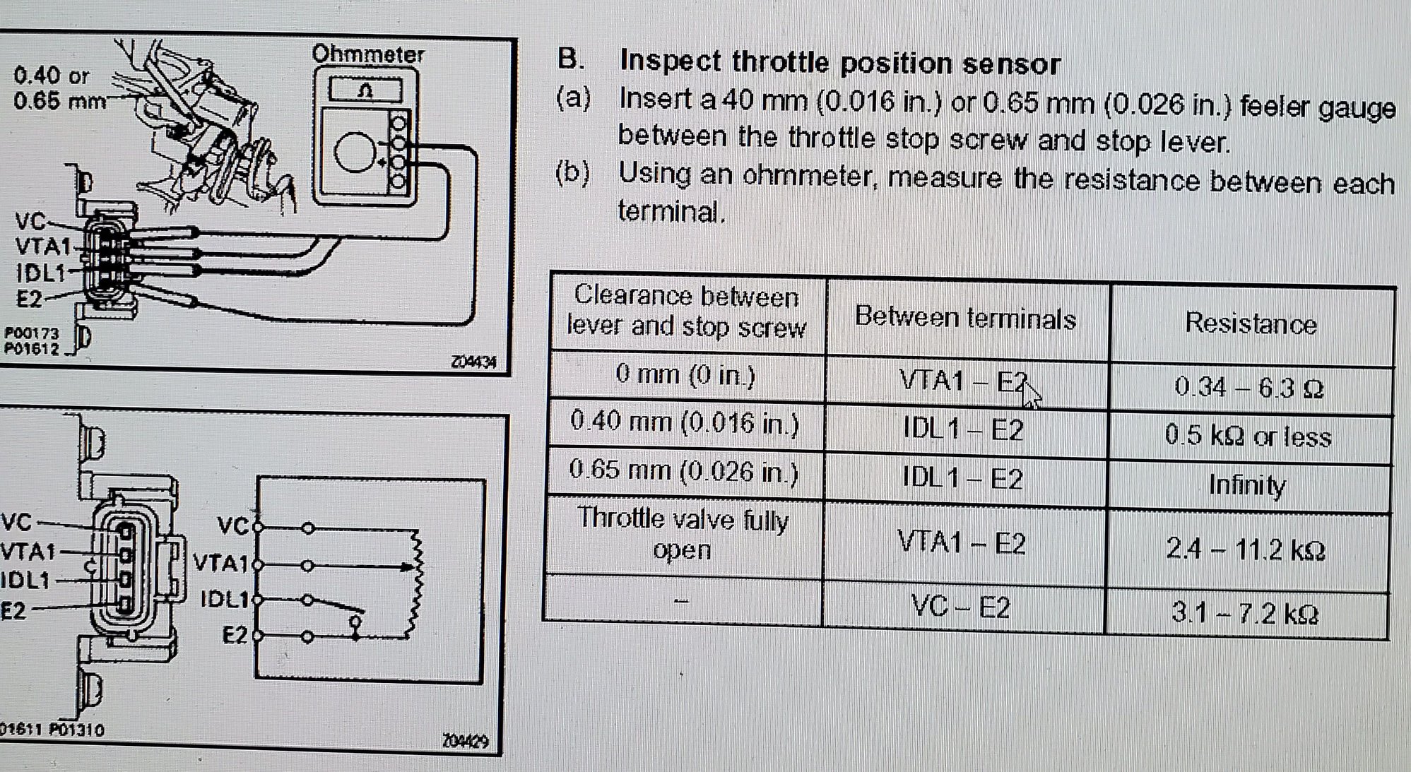
Again, look at the thread. You need to look for resistance and continuity. And you also need to have some really narrow feeler gauges (0.65mm and 0.45mm).
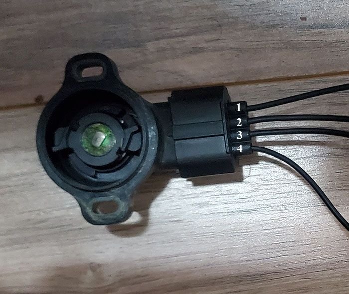
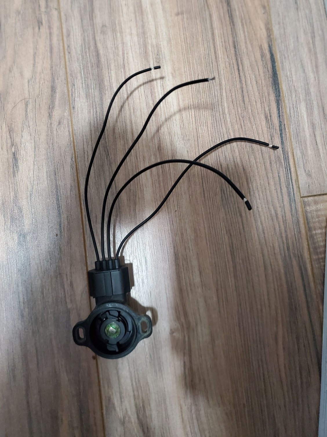
Now unplug the sensor wire and plug in your connector. Place the 0.65mm feeler gauge under the stop screw. Jam the multi-meter pins into the back of the other connector so they hold themselves in. Pins go to #1 yellow and #2 black, there are numbers on the plug. Multi-meter set to continuity. Now rotate the sensor all the way to one side and all the way to the other, find the exact instant the continuity shuts off and tighten one screw. Now insert the 0.45mm and continuity should be restored. (Continuity on some multi-meters is a beep to show two items are connected. If you've never used the meter before and you want to test it, make sure not to touch the pins to each other as it could damage the unit. Touch something that’s metal instead.)
Now change to resistance mode and using the same #1 & #2 wires it should read “0.34-6.3” ohms as stated in the pdf. Now change to pins #1 & #3 and insert the 0.45mm. It should read under 0.5k ohms. Note: No matter what I do, my sensor sits around 700 ohms, I might need a new one but I’d love to compare notes with someone else…
Now when you insert the 0.65mm feeler the resistance should go to infinity. On my meter it reads 0.0 Million ohms.
That’s it, you’re done. Start and stop the car a few times to test everything out and take it for a test drive and let us know how it worked out for you.
#66

Measure the old one and the new one I see the differences:
- Resistor between 1 and 4: old = 4.67 kohm / new = 3.55 kohm
- Resistor between 2 and 4: old = 25,5 ohm / new = 77.5 ohm
- Resistor between 3 and 4: old = 56.3 ohm / new = open circuit ????????
- Resistor between 3 and 1: old = 4.7 kohm / new = open circuit ????????
- Resistor between 3 and 2: old = 81,5 ohm / new = open circuit ???????
- Resistor between 2 and 1: old = 4,7 Kohm / new =3,6 Kohm
It means that pin 3 of the new is isolated to other pins, while pin 3 of the old is connected. What TPS is right?
Open the connector, the voltage apply to pin 2 is 11.5V and to pin 4 is 5V, are these voltage ok?
#67
I think TPS is an variable resistor with 3 wires: 2 wires is ground and 5VDC or 12VDC, the remain wire has voltage change due to Throttle position, output to ECM, indicate the throttle position.
I do not know why my TPS having 4 wires and with 5V and 12V
I do not know why my TPS having 4 wires and with 5V and 12V
#69
Pole Position
Why do you have 4 pins - you are right, this sensor is a potentiometer of sorts. But in your case, your TPS is combined with the Idler Switch, which gives you the fourth pin and an error that you have.
About sensor resistance - it does seem like your new sensor is an aftermarket, so that may be your issue. Still, it seems like both of them are in specs, so you choose which one to install. I would better stick with OEM parts.
And about the feeler gauges - to be honest, I am not sure about that, since I have a different kind of sensor. It looks to me though as the stop lever will not touch the stop screw while driving, that is why you need those feeler gauges. You can test that theory after the adjustment by looking for a gap between screw and the lever.. With that said, I am sure that it is an official setting procedure.
P.S. I also found another post about adjusting the sensor, it has a bit more visuals..
Hope this helps and best of luck!
#70
Test TPS
Apply 5VDC to pin 1 (+5VDC) and pin 4 (ground). Measure pin 3 (TP signal) voltage: turn the throttle --> pin 3 voltage increases in both TPS, old and new.
Measure pin 2 (maybe idle signal or something i do not know) the voltage unchanged when rotating.
So I know that both TPS are good in variable resistor to measure TP position. But I do not know why in the old one, the Idle pin is not isolated with other pins like in the new one. If the Idle pin is not isolated can we conclude that TPS is damaged?
So what is the problem now and what I should do? It is not only replace the new one.
Last edited by anhtran; 02-13-20 at 08:17 PM.
#71
Pole Position
Test TPS
Apply 5VDC to pin 1 (+5VDC) and pin 4 (ground). Measure pin 3 (TP signal) voltage: turn the throttle --> pin 3 voltage increases in both TPS, old and new.
Measure pin 2 (maybe idle signal or something i do not know) the voltage unchanged when rotating.
So I know that both TPS are good in variable resistor to measure TP position. But I do not know why in the old one, the Idle pin is not isolated with other pins like in the new one. If the Idle pin is not isolated can we conclude that TPS is damaged?
So what is the problem now and what I should do? It is not only replace the new one.
Apply 5VDC to pin 1 (+5VDC) and pin 4 (ground). Measure pin 3 (TP signal) voltage: turn the throttle --> pin 3 voltage increases in both TPS, old and new.
Measure pin 2 (maybe idle signal or something i do not know) the voltage unchanged when rotating.
So I know that both TPS are good in variable resistor to measure TP position. But I do not know why in the old one, the Idle pin is not isolated with other pins like in the new one. If the Idle pin is not isolated can we conclude that TPS is damaged?
So what is the problem now and what I should do? It is not only replace the new one.
#73
Pole Position
#75
Pole Position
Also, a really similar problem popped up recently on this forum, so maybe you would want to keep an eye on it, just in case.. Here is a link: https://www.clublexus.com/forums/es-...-no-power.html.
Hope this helps and best of luck!


