When you click on links to various merchants on this site and make a purchase, this can result in this site earning a commission. Affiliate programs and affiliations include, but are not limited to, the eBay Partner Network.
You will probably have to t-pin into Pins 4 and 5 of the fuel pump and see if the power is still present when the car dies. Also try to short the Circuit Opening Relay and see if the car will continue running.
USING THIS?...All you need to check for right now is whether the pump will turn on if you would short the Switch side of the Circuit Opening Relay, that is like a big fork on the road, which will dictate your next move.
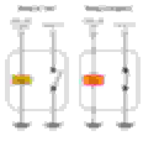
Below is a basic pinout of a relay, red rectangles represent pins that should be powered when the ignition is on the ON position. Short two vertical pins, or Switch pins, and see if the pump will engage. Then put a test light across horizontal, or Coil pins and crank the engine, see if it will light up. If all that's good, replace the Relay. If there is no power on any of the pins, you will have to take the fuse box apart, it's cumbersome, but doable. If the light bulb won't light up, you will have to check the wire from the relay to ECU. If the pump won't engage, then your schematics is probably the way to go, since to combat it, you will have to take half of the interior out and trace the wire from the fuse box all the way to the fuel pump.
The reason why I am telling all that is because your schematic says to use a pump power wire as a switch for the relay, but yours is out of commission, sine otherwise this thread wouldn't exist. The way to combat it is to either use a separate switch, or connect it to the Coil side of the Circuit Opening relay, if it is getting power. The switch is pretty self-explanatory, as for the relay, it is controlled by Ground, so you will have to connect Pin 86 to the Circuit Opening Relay, and Pin 85 to constant 12V supply. Doing so will require you to check if your relay coil is getting triggered, as I explained above, if the ECU does not trigger the relay, your only way out would be to wire a switch and click it on and off each time you go to start a car.
Yes, you need to short the Switch pins, do not confuse them! The Switch side on the relay has Golden-Copper pins, those are what you need to short, then listen if the pump will start spinning.
Pins 85 and 86 are not in any way related to the setup that is currently on your car, with those, I was referring to the relay pins showed on the bypass diagram you linked earlier, they have nothing to do with the Circuit Opening Relay that is currently in the car.
All you need to check for right now is whether the pump will turn on if you would short the Switch side of the Circuit Opening Relay, that is like a big fork on the road, which will dictate your next move.
Below is a basic pinout of a relay, red rectangles represent pins that should be powered when the ignition is on the ON position. Short two vertical pins, or Switch pins, and see if the pump will engage. Then put a test light across horizontal, or Coil pins and crank the engine, see if it will light up. If all that's good, replace the Relay. If there is no power on any of the pins, you will have to take the fuse box apart, it's cumbersome, but doable. If the light bulb won't light up, you will have to check the wire from the relay to ECU. If the pump won't engage, then your schematics is probably the way to go, since to combat it, you will have to take half of the interior out and trace the wire from the fuse box all the way to the fuel pump.
The reason why I am telling all that is because your schematic says to use a pump power wire as a switch for the relay, but yours is out of commission, sine otherwise this thread wouldn't exist. The way to combat it is to either use a separate switch, or connect it to the Coil side of the Circuit Opening relay, if it is getting power. The switch is pretty self-explanatory, as for the relay, it is controlled by Ground, so you will have to connect Pin 86 to the Circuit Opening Relay, and Pin 85 to constant 12V supply. Doing so will require you to check if your relay coil is getting triggered, as I explained above, if the ECU does not trigger the relay, your only way out would be to wire a switch and click it on and off each time you go to start a car.
Hope this helps and best of luck!
Join Date: Nov 2019
Location: Michigan
Posts: 779 Likes: 23
Received 188 Likes on 167 Posts
Defaultok forget numbers ,,You said ...Yes, you need to short the Switch pins...im asking where are the switch pins ?
Wait a second, I clearly marked two stacked pins on the bottom of the socket, not just some random pins! With the jumper, you act as a switch in the relay, turning the pump on; you, on the other hand, tried to power the pump from a Signal 12V supply, which is not how it works. A relay has a coil, once the power comes through it, a magnetic filed of the coil switched the relay on or off. Every coil has a certain resistance, which is why it doesn't fry the ECU each time it is triggered.
To make some sense of what we are trying to do here, the jumper is used in place of that switch in the relay. As for the Test Light section, it is to test whether the signal from the ECU is actually getting to the Relay, where a Test Light would sit in place of the coil, so that once the power goes through it, the bulb would light up. To work out which set of pins in a relay belongs to Switch or the Coil, measure the resistance across set of pins, if there is None, it is a Switch side, if there is resistance, then it is a Coil side.

 05-14-21 | 09:46 AM