
KiPod's GS Pic & Mod thread

 07-21-10 | 07:34 AM
#122
 07-21-10 | 08:42 AM
#123
Thread Starter
Lexus Test Driver
iTrader: (31)
Joined: Aug 2006
Posts: 1,354
Likes: 6
From: All Around Our Nation's Capital
Thanks, I'm loving them more each day. I have to go through the wiring again to make a clean list of what goes where & what you don't need. Here is a glimpse of what I was doing.
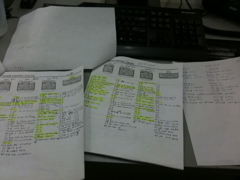
Nothing major, but no way to tell until I hit the track again to see.
Nothing major, but no way to tell until I hit the track again to see.
Last edited by KiPod; 07-27-10 at 12:54 PM.
09-02-10 | 12:53 PM
#124
Thread Starter
Lexus Test Driver
iTrader: (31)
Joined: Aug 2006
Posts: 1,354
Likes: 6
From: All Around Our Nation's Capital
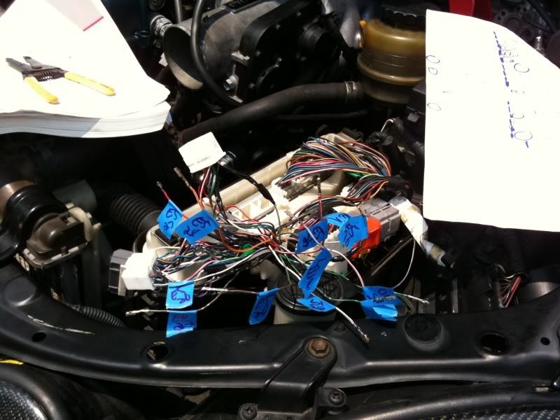
Okay, here is the info for what ECU pins I moved for the swap. If the pins were in the same spot I left them alone & will skip them on the list. I only listed the wires that need to be moved to a different location or removed from the connector. I will list the connector w/ pin where it was for the 98 GS400 then where it needs to be for the Aristo.
Connectors E2, E3, & E4 run from the engine to the ECU so they should all be in the correct place alreay (if your swap came with ECU & harness together). Connectors E5, E6, & E7 are from the vehicle body to the ECU so these need to be moved to match the new ECU. On my Aristo ECU there was no slot for the E7 connector so I listed those as "remove" as well.
If I say "remove" it's because it is either already in the correct location on the Aristo harness (in connector E2, E3, or E4) or you don't need this wire. You should remove it from the connector and tape it off. The list should read like this,
98 GS400 location (Wire Color) - Aristo location
So, you would move pin 2 on connector E5 on the GS400 harness (Red wire with Black stripe) to pin 16 on connector E5 for the Aristo ECU.
E5 pin 2 (RED/black) - E5 pin 16
E5 pin 3 (GREEN/black) - remove
E5 pin 4 (GREEN) - remove
E5 pin 7 (GREY/black) - remove
E5 pin 8 (GREY) - remove
E5 pin 10 (WHITE/red) - remove
E5 pin 15 (RED/white) - E5 pin 26
E5 pin 16 (BLACK/yellow) - connect to ignitor for tach signal (you will need a tach adapter to get it to work with a 400 cluster)
E5 pin 17 (BLACK) - E5 pin 2
E5 pin 18 (WHITE) - E5 pin 8
E5 pin 19 (WHITE/green) - remove
E5 pin 20 (GREEN/red) - remove
E5 pin 22 (BLUE/yellow) - E5 pin 18
E5 pin 25 (RED/white) - remove
E5 pin 26 (WHITE/black) - E6 pin 22
E5 pin 27 (RED) - remove
E5 pin 28 (YELLOW/red) - remove
E6 pin 3 (BLUE/black) - E3 pin 8
E6 pin 22 (GREEN/red) - E6 pin 15
If your Aristo ECU is like mine & doesn't have a slot for the E7 connector, you don't have to remove these wires. Since the connector is left hanging loose it will not interfere with anything.
E7 pin 1 (YELLOW/black) - E5 pin 17
E7 pin 2 (BLUE/yellow) - remove
E7 pin 3 (VIOLET or Purple) - remove
E7 pin 4 (WHITE/black) - remove
E7 pin 11 (WHITE) - E5 pin 28
E7 pin 14 (BLACK/blue) - E5 pin 11
E7 pin 15 (RED/green) - remove
E7 pin 16 (RED/yellow) - remove
E7 pin 17 (BLUE/red) - remove
E7 pin 18 (GREEN/black) - remove
E7 pin 19 (BLACK/white) - remove
E7 pin 20 (YELLOW) - remove
E7 pin 21 (GREY) - remove
E7 pin 22 (LIGHT GREEN/red) - E5 pin 10
E7 pin 23 (BLUE/black) - E5 pin 21
E7 pin 24 (BLACK) - E5 pin 27
E7 pin 25 (YELLOW/green) - E5 pin 7
E7 pin 26 (PINK/blue) - E2 pin 26
Sorry, if it's confusing. Sometimes things make sense in my mind but they don't come out as coherent. I think there were 1 or 2 other wires I had to move to get the shift indicator & shift lock to work. I think they were in the grey junction block beside the ECU & next to the orange junction block. I can't remember for sure though. If someone does this and runs into a problem with them I can check to see what mine look like.
Last edited by KiPod; 09-24-10 at 05:36 AM.
 09-02-10 | 05:31 PM
#126
Thread Starter
Lexus Test Driver
iTrader: (31)
Joined: Aug 2006
Posts: 1,354
Likes: 6
From: All Around Our Nation's Capital
Yup, E7 is mainly for immobilizer & my VSC doesn't work. You don't need to run a wire from ignitor to ECU though. Maybe on the 300's but on the 400's you run the wire from ignitor to tach signal. The 300's and Aristo's get the tach signal from the ignitor. The 400's get the tach signal from the ECU. Just jump the old tach signal wire that used to go into the ECU straight into the open slot in the ignitor. Since the cluster is expecting a different signal your tach will be off. I used a Dakota Digital tach adapter to fix the problem when I had the TRD 2JZ cluster running off a 1UZ signal. It should work the other way as well. I basically swapped all my wires into GS300 locations so if you swap into a 98-00 300 you wouldn't have to do all that.
09-24-10 | 06:13 AM
#127
Thread Starter
Lexus Test Driver
iTrader: (31)
Joined: Aug 2006
Posts: 1,354
Likes: 6
From: All Around Our Nation's Capital
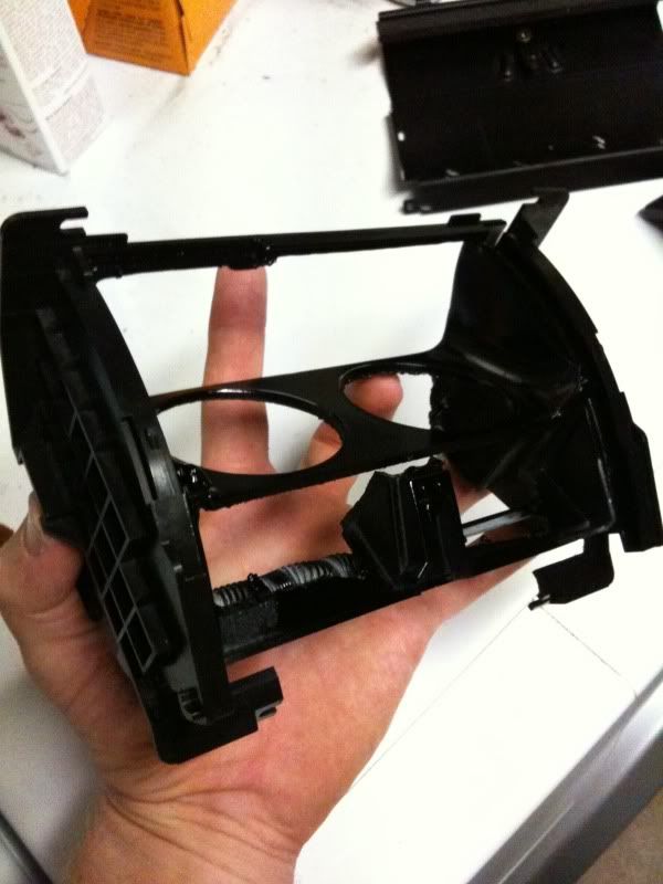
So I took apart the ash tray. Then, I trimmed the main tray portion to open it up. I used wood for the gauge mount, epoxy to hold it together, bondo to smooth it all out, & then painted it all black.
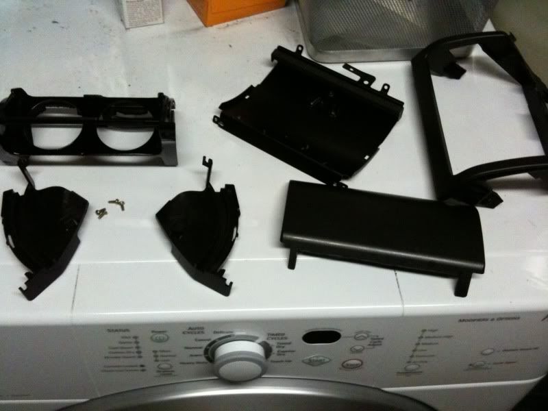
Best of all, it still closes. This was before I had the wideband hooked up.
http://www.youtube.com/watch?v=82Rsm...e_gdata_player
I had to trim a lot to make it fit. It was close between the back of the gauge hitting when closed & the front gauge bezels rubbing.
Best of all, it still closes. This was before I had the wideband hooked up.
http://www.youtube.com/watch?v=82Rsm...e_gdata_player
I had to trim a lot to make it fit. It was close between the back of the gauge hitting when closed & the front gauge bezels rubbing.
09-24-10 | 09:22 AM
#130

Driver School Candidate
Joined: Jan 2010
Posts: 24
Likes: 0
From: CA
So I took apart the ash tray. Then, I trimmed the main tray portion to open it up. I used wood for the gauge mount, epoxy to hold it together, bondo to smooth it all out, & then painted it all black.
Best of all, it still closes. This was before I had the wideband hooked up.
http://www.youtube.com/watch?v=82Rsm...e_gdata_player
I had to trim a lot to make it fit. It was close between the back of the gauge hitting when closed & the front gauge bezels rubbing.
Best of all, it still closes. This was before I had the wideband hooked up.
http://www.youtube.com/watch?v=82Rsm...e_gdata_player
I had to trim a lot to make it fit. It was close between the back of the gauge hitting when closed & the front gauge bezels rubbing.
09-24-10 | 04:02 PM
#131
Thread Starter
Lexus Test Driver
iTrader: (31)
Joined: Aug 2006
Posts: 1,354
Likes: 6
From: All Around Our Nation's Capital
Thanks guys. I know sometimes you want/need to see the gauges. But if you're on a long road trip (or get pulled over on said road trip  ) it's good to be able to put them away. I remember when I went to emissions years ago in my turbo mustang, i had like 7 gauges in the car and the guys doing the test gave me the weirdest looks.... then it passed
  .
.  to highflow cats.
) it's good to be able to put them away. I remember when I went to emissions years ago in my turbo mustang, i had like 7 gauges in the car and the guys doing the test gave me the weirdest looks.... then it passed . to highflow cats.
10-09-10 | 05:19 PM
#132
Thread Starter
Lexus Test Driver
iTrader: (31)
Joined: Aug 2006
Posts: 1,354
Likes: 6
From: All Around Our Nation's Capital
Okay, so I had a feeling my car was running rich all the time. It just didn't feel "light" & responsive like I thought it should. Once I hooked up the wideband I saw that I was idling, cruising around 12.3 AFR. Way too rich & I asked about O2 sensors in this thread...
https://www.clublexus.com/forums/per...bo-owners.html
Once I swapped the new sensor in my AFR was right back in high 14's like it should be. The car is finaly feeling as I thought it would. So, last night I went to the track again and I went from 2.3 60ft w/ 14.3 1/4 to a 2.0 60ft w/ 13.8 1/4. That's the best O2 sensor purchase I have ever made. Half a second difference with one new sensor in place.
So, yup I'm sitting at 13.8 1/4 @ 100mph w/ 2.0 60ft
Stock turbos, stock sidemount intercooler, stock Aristo Cat, & STOCK BOOST.
I'm gathering parts for single turbo and hooking up the MAP-ECU2 now. I will keep posting #'s as they change.


