When you click on links to various merchants on this site and make a purchase, this can result in this site earning a commission. Affiliate programs and affiliations include, but are not limited to, the eBay Partner Network.
If you can wait a couple weeks, I found a set at a decent price. I'll poke at it to see what can be done and/or how easy is it to open up to make changes.
I went with your option1 on my 2015 GS and the DRL works fine during day and night. But the light switch must not be placed at DRL off. If set at DRL off, the DRL will light up at dim brightness every time i hit the brake. Then a rock on freeway destroyed my headlight and I replaced it with a used one on ebay, which I suspect it was from 2013-2014 model and the DRL acted very weird. It was never light up at full brightness, completely off at night, dim at daytime driving and off once tap brake. . So i think it really depends on which MY,
It looks to be a PWM driver, so will only serve to dim. Because the "max brightness" of the inner light is already what it is now (which is dimmer than brake light) then this wouldn't increase your brightness.
However what this could be useful for would be if the lights were made to output brighter (possibly by opening them and changing component), then using this to dim them back down to "tail/running light" level. I have to see when I get the set of lights.
If you can wait a couple weeks, I found a set at a decent price. I'll poke at it to see what can be done and/or how easy is it to open up to make changes.
So basically, for your Option 2, you're doing this.
Find the cable the runs the RHS brake light.
T-off that cable with your 18-gauge wire.
Meanwhile, find the cable that powers the right rear inner park light.
Interrupt that cable with the Y-type diode in the middle.
Then, connect the 18-gauge wire from the RHS brake light into the second input of the Y-type diode to give a dim inner red light upon braking.
For the LHS inner weak brake light, find the LHS rear inner park light cable, and interrupt it with the 2nd diode.
From the original T-off 18-gauge RHS brake wire, T-off another 18-gauge wire to the 2nd input of the LHS diode, so that the LHS inner red light will illuminate dim upon braking.
That sounds right?
Yea, that is one way.
The part where you have the green font, you can T-tap that, or you can just do two red (assuming you're using red) wire inside one crimp connector. If using 18 gauge wire, two wires combined into one crimp connection will be about a 14 AWG thickness, so you'd use a blue crimp connector.
This video (from a possible member on here) shows routing. It's for a 4.5 tail light retrofit, but does involve running the brake light wire. Here, it looks like they combined the connection on the RH taillight connector itself, then ran that wire over to the LH side.
The wiring description at the end (2:08) he mixed up the stop light color. For the right hand outer light, solid white wire is the stop light. It's mentioned correctly at 0:32.
I'm still going to try to open some lights up (when I get them) to see if the original intent of the thread can be done easily, which is to make the inner light the same brightness, hopefully making the need of the external diode irrelevant. We'll see...
Small update now that I got a chance to play with these a bit.
It looks like the brake lights in the outer lights are actually split into two groups. A 3 x 3 set and a 3 x 2 set.
When in tail light mode, both the inner 3 x 3 and the outer 3 x 3 use the same current across various voltages. This leads me to believe they are driven by a similar value resistor and very likely the same LED chips.
For braking, the bottom 3 x 2 set is driven differently than the top 3 x 3 set. They start to illuminate at around 5V versus the 2.X volts that the 3
x 3 set illuminates at, but quickly increase in brightness as voltage rises. If you give them 15 V, the bottoms set will actually start being brighter than the top 3 x 3 set.
At 14V, braking consumes 4.9W, but I'm sure a good chunk is from the bottom set.
I'll try to cut open the inner set this week to try and change out resistors. With any luck, I might be able to close them back up.
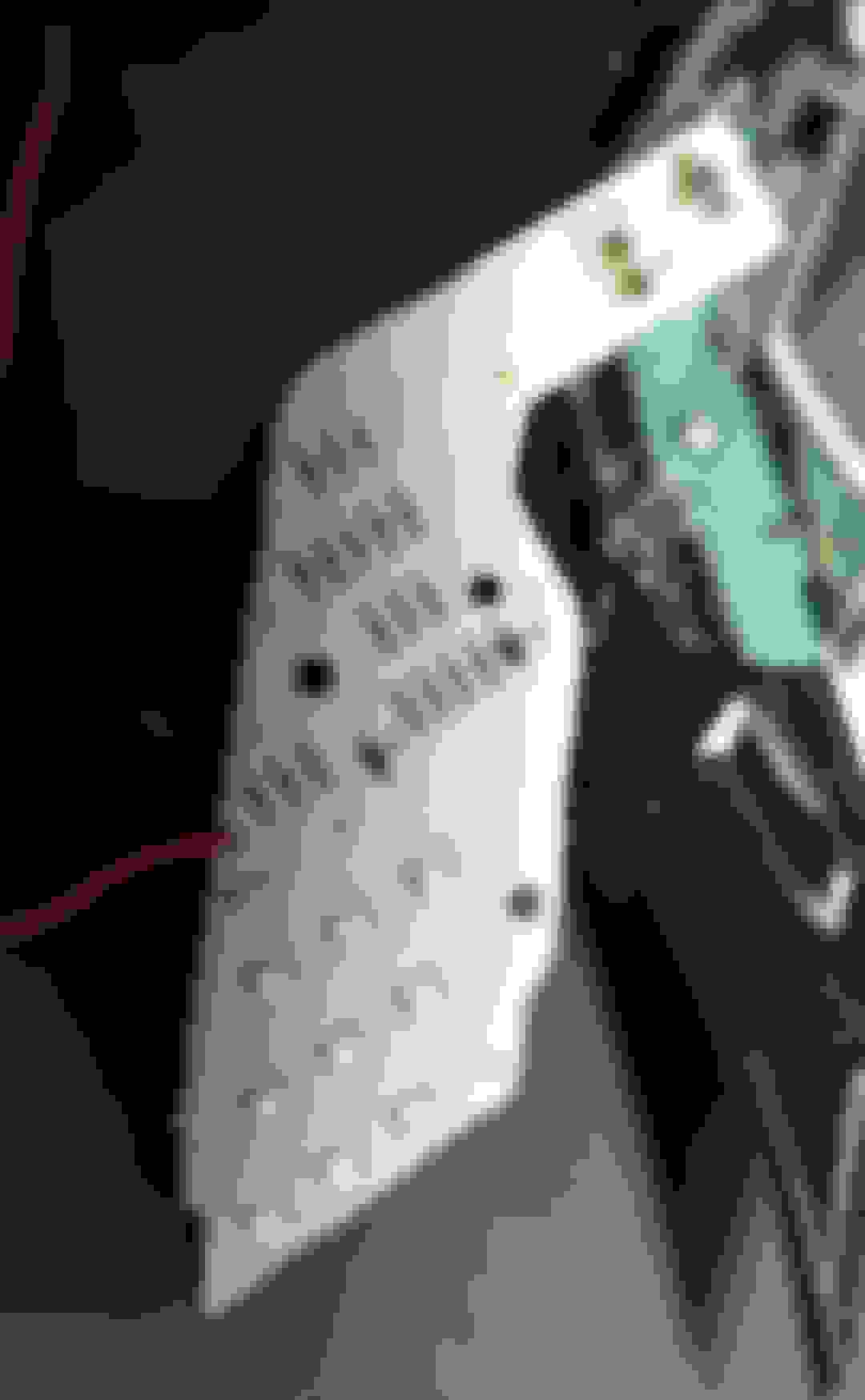
One of the lights is cut open, and already have the regulator and resistors hooked up.
You cut around until you see black. For the second light, I will try to just cut around the LED light board to not have to mess with realigning the lens covers on correctly.
Light without the red cover. Looks kind of cool.
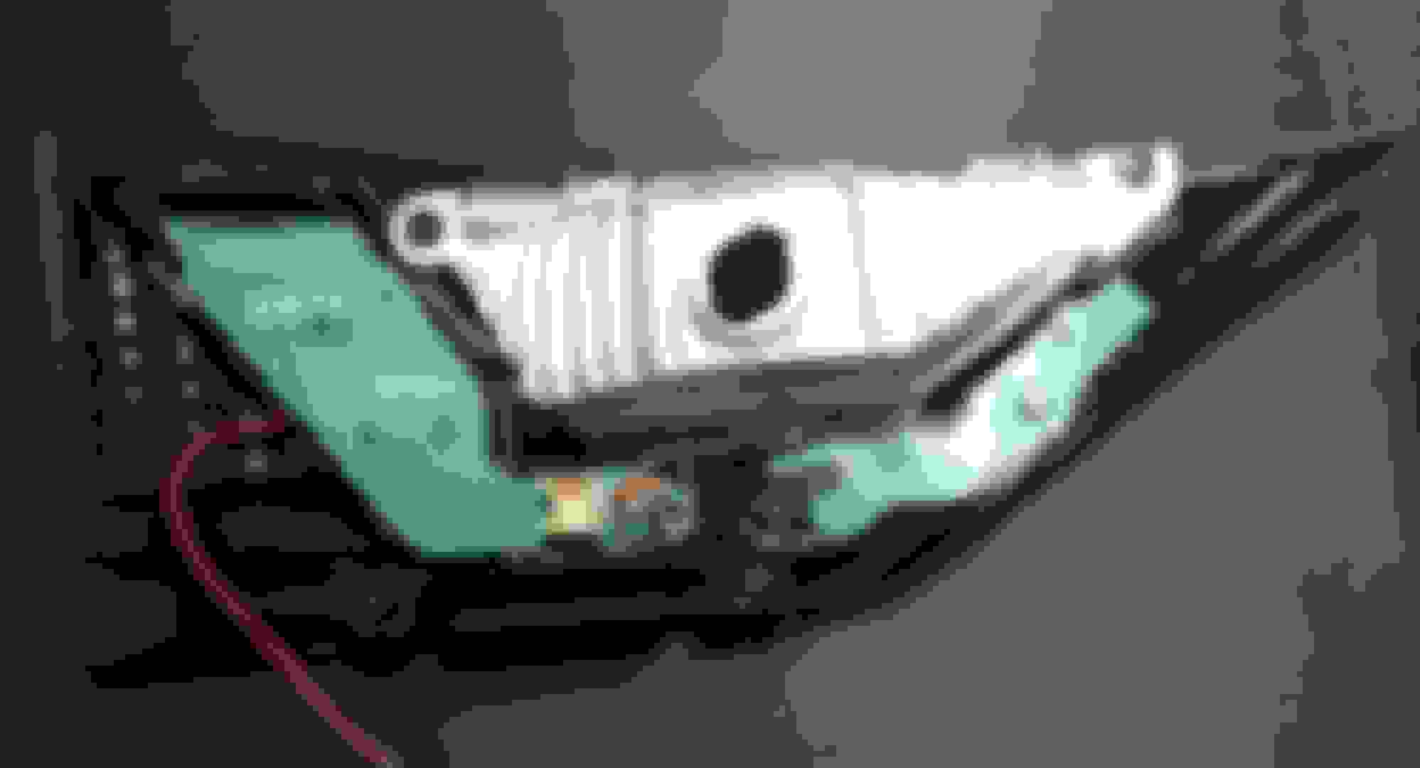
Back of light. Left is the main tail light section and right are 4 LEDs for the accent lighting (for the light pipes). Red wire is for testing. The reverse light area is individually removable.
Main taillight board. The three left resistors are for the tail lights. Three branches of three LEDs in series.
The rest of the resistors are for the pipe/accent lights. Since there's less, there's less voltage drop, so more resistors are needed.
The same LEDs are used for both accent and taillight.
After some comparison, it seemed that driving the taillight at 150 - 170 mA gave the best trade off between closeness to brake lights and not heating up top much. I left them running at 155 mA for 40 mins and they only got to 120 F. Obviously, things would be a little different in a hot day but main thing was that temperature wasn't shooting up.
I initially tried to use just resistors, but all the 2W resistors I had would heat up pretty quickly, when when using multiple in parallel to get to 50 ohms. I considered a 50W 50 ohm aluminum one, but wasn't sure if 1.2W would be dissipated fast enough.
I looked at constant current drivers, but most would not work because they require the LED(s) to be isolated and not share a ground with another set of LEDs.
Finally, I settled on just using a compact switching power supply that outputs 6.5V and drives a pair of 5 ohm resistors in parallel. Since the voltage drop is only around 0.5V, the heat dissipated by them is negligible.
The resistors can be hidden inside the light. The supply could be as well, but honestly, I'm not sure on the longevity. They have a 3 yr warranty. So, to make things more serviceable, the resistors will be inside the light (passive components do not normally fail), and the "module" will be outside the light, connected via 3 wires and a quick disconnect to the light. The one input will be the the stop light signal.
Some output shots
Current headlights off, brakes on.
Updated, headlights off, hitting brakes. I think it looks better if the accent lights of the inner light illuminate, similar to the 4.5 ones. If it looks bad, it's just disconnecting one wire.
Current, headlights on, brakes on.
Updated, headlights on, brake on.
I might try lowering the resistance just a smidge to get them a little bit brighter, since I ended up only pushing 145 mA currently.
The hard part will be, of course, sealing them back up straight, but that's for another day.
The LEDs are the OEM ones, in OEM setup, so I'm guessing they are fine in their current setup
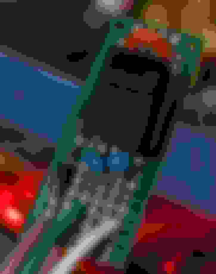
The regulator itself is 2725-K78UX6-500R3L-ND, which is just supposed to be a 78XX switching substitute. It needs a 10 uF input cap and 22 uF output cap. If this one sucks, there were a couple other alternatives (a little more pricy) that could be substituted.
The other diodes in the picture are just to be able to light up the accent lights when the brake is on. I'm connecting in after the OEM resistors and adding in my own regulator/resistors. I'll draw up the diagram once values are finalized.
One of the lights is cut open, and already have the regulator and resistors hooked up.
...
I might try lowering the resistance just a smidge to get them a little bit brighter, since I ended up only pushing 145 mA currently.
The hard part will be, of course, sealing them back up straight, but that's for another day.
Is it possible that the higher current applied to the inner red lights may cause the inner red LED's to burn-out faster if the inner red LED's do not have the same ratings as the outer red LED's?
Possible? Sure. Though based off the behavior and current measured in post 37 between inner and outer, it's likely at least the 3x3 of both lights use the same LEDs. I'm unsure what LEDs are used in the brighter 3x2 section. They could be the same or something else that can handle the extra 2-3 W of power.
The inner LEDs are PLCC4. Looking around at different ones currently available from Vishay, Osram, Rohm, etc they all seem to have a typical current of 50mA, with an absolute max of 70mA. Cree has some that'll do 200 mA, but it's unlikely the case here.
One of the main enemies of LEDs are heat and in this case, I'm guessing the current limitation comes from the package.
Since it's 3 branches of 3, and right now the total LED circuit consumes close to 150, that puts it around 50 mA per branch/per LED. So I think 150 is that max I'd do to not over do it.
EDIT: if I had to take a bet, I'd say they are OSRAM TopLEDs: https://ams-osram.com/products/leds/...63b#Datasheets
It looks like this is discontinued, which makes sense if it was used in prior years. Applications include automotive indication, and OSRAM is a big name supplier. They have a newer version that achieves test brightness at 20 mA instead of 50 mA, so it might be a possible solution if trying to go resistors only route. You'd just have to recalculate the tail light values for the dimmer output and replace those SMD resistors. Maybe something for a later project.
 02-26-24, 11:04 PM


 . So i think it really depends on which MY,