Help with wiring for Triple-Beam headlights
#46
Pit Crew

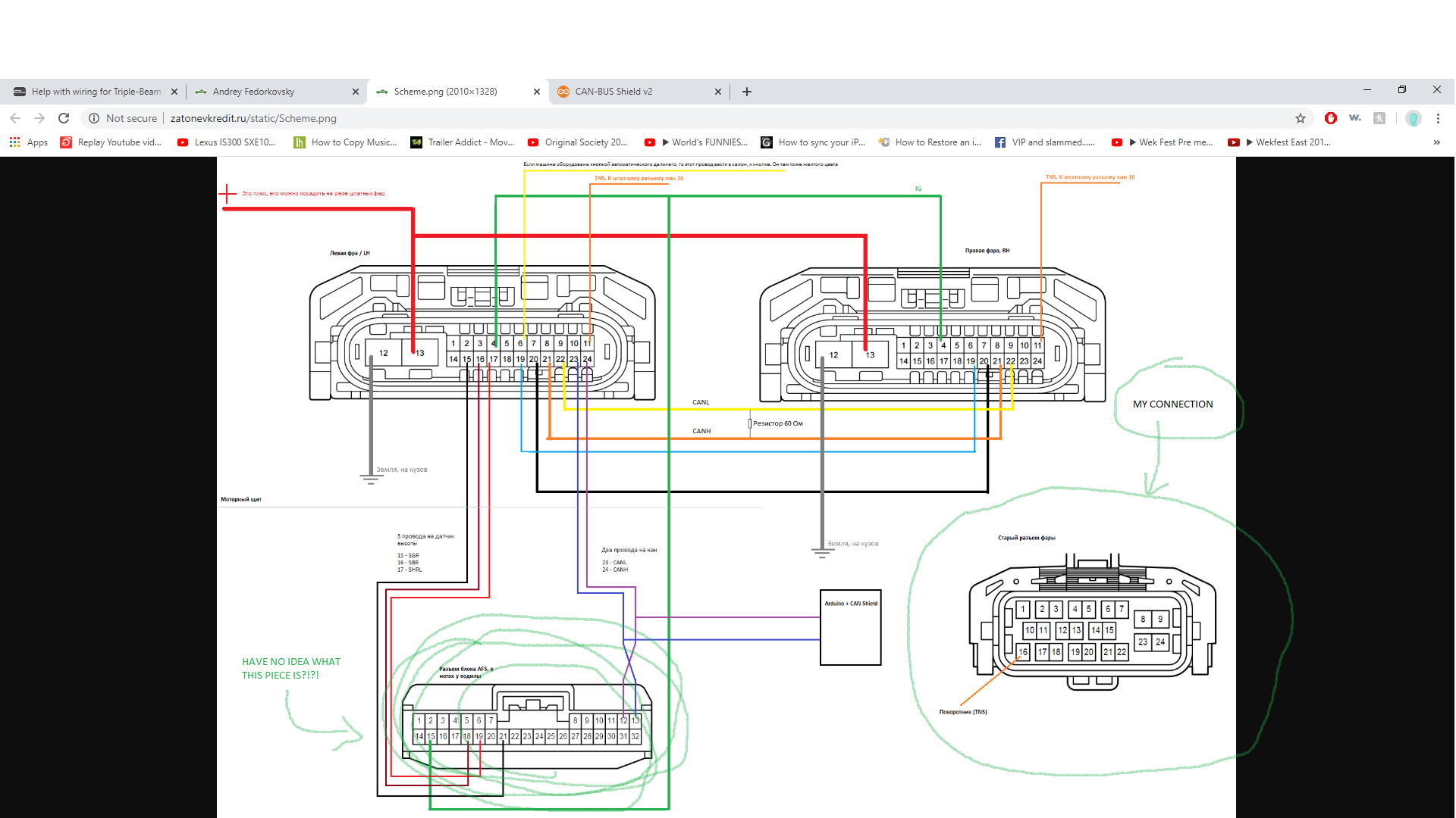
Hi, would you be able to explain step by step which wire goes to which number from the new headlight module to the cars headlight harness. The Russian guy's diagram is confusing and I have no idea that that bottom left piece is. My connector is exactly like the one on the bottom right. If you could draw it out out just send it through here that would be amazing.In much need of help right now.
#47
Driver School Candidate
Join Date: May 2016
Location: texas
Posts: 11
Likes: 0
Received 0 Likes
on
0 Posts
Thank you so much!! So let me get this straight, the yellow, blue, green, orange and black wires, they connect from one headight to the other headlight?? Then I just use one headlight to connect to the ecu? And what would I do with the harness that connect to my original headlight (bottom right pic)
#48
Driver School Candidate
Join Date: May 2016
Location: texas
Posts: 11
Likes: 0
Received 0 Likes
on
0 Posts
Thank you so much!! So let me get this straight, the yellow, blue, green, orange and black wires, they connect from one headight to the other headlight?? Then I just use one headlight to connect to the ecu? And what would I do with the harness that connect to my original headlight (bottom right pic)
#49
Thank you so much!! So let me get this straight, the yellow, blue, green, orange and black wires, they connect from one headight to the other headlight?? Then I just use one headlight to connect to the ecu? And what would I do with the harness that connect to my original headlight (bottom right pic)
You connect + and ground wires to the old harness, as well as turn signal lights, each side respectively.
However, diagram is missing one key point - in order to have all things working as supposed, you have to replace Body MPX ECU with a 16+ one, otherwise you will not be able to initialize the AFS in the headlights and you will have a constant error beep, or only low beams and no DRLs.
I have spare new headlight harness connectors and some other stuff, PM me if interested
Last edited by DeneAlex; 06-29-20 at 07:06 PM.
#50
DeneAlex do you have the part number for the mpx? How hard was it to install that piece? Thanks
Correct! yellow, blue, green, and black wires connect headlight ECUs. Left headlight is a master headlight, you connect it to AFS ECU connector to the wires indicated (can wires, level sensor wires, and IG wire.
You connect + and ground wires to the old harness, as well as turn signal lights, each side respectively.
However, diagram is missing one key point - in order to have all things working as supposed, you have to replace Body MPX ECU with a 16+ one, otherwise you will not be able to initialize the AFS in the headlights and you will have a constant error beep, or only low beams and no DRLs.
I have spare new headlight harness connectors and some other stuff, PM me if interested
#51
Driver School Candidate
Join Date: May 2016
Location: texas
Posts: 11
Likes: 0
Received 0 Likes
on
0 Posts
Correct! yellow, blue, green, and black wires connect headlight ECUs. Left headlight is a master headlight, you connect it to AFS ECU connector to the wires indicated (can wires, level sensor wires, and IG wire.
You connect + and ground wires to the old harness, as well as turn signal lights, each side respectively.
However, diagram is missing one key point - in order to have all things working as supposed, you have to replace Body MPX ECU with a 16+ one, otherwise you will not be able to initialize the AFS in the headlights and you will have a constant error beep, or only low beams and no DRLs.
I have spare new headlight harness connectors and some other stuff, PM me if interested
You connect + and ground wires to the old harness, as well as turn signal lights, each side respectively.
However, diagram is missing one key point - in order to have all things working as supposed, you have to replace Body MPX ECU with a 16+ one, otherwise you will not be able to initialize the AFS in the headlights and you will have a constant error beep, or only low beams and no DRLs.
I have spare new headlight harness connectors and some other stuff, PM me if interested
Sounds good, where would 6 and 11 go for the new headlights? And 23 & 24 goes straight to 12 & 13 on the ecu? What is that arduino and can shield? What about number 16 for the old connector, just shows a blank orange line. Besides the body MPX ecu, is there any other components I would need to buy? Sorry for all these questions, trying to install my headlights properly, donít want to run into any problems mid way hahaha.
#52
You can omit wire 6 connection (it goes to auto high beam light button in the dash), wire 11 goes to old harness wire 16 (turn signal, as indicated on diagram).
You can google about arduino and can shield, but obviously you don't need them. As i said, you have to replace Body MPX ECU with a 16+ one (I used MPX from 2019 Lexus GSF 89221-30451 and it worked perfectly), otherwise you will not be able to initialize the AFS in the headlights and you will have a constant error beep, or only low beams and no DRLs. You need to have Toyota Techstream and working OBD cable to program ECUs
You can google about arduino and can shield, but obviously you don't need them. As i said, you have to replace Body MPX ECU with a 16+ one (I used MPX from 2019 Lexus GSF 89221-30451 and it worked perfectly), otherwise you will not be able to initialize the AFS in the headlights and you will have a constant error beep, or only low beams and no DRLs. You need to have Toyota Techstream and working OBD cable to program ECUs
#53
Driver School Candidate
Join Date: May 2016
Location: texas
Posts: 11
Likes: 0
Received 0 Likes
on
0 Posts
You can omit wire 6 connection (it goes to auto high beam light button in the dash), wire 11 goes to old harness wire 16 (turn signal, as indicated on diagram).
You can google about arduino and can shield, but obviously you don't need them. As i said, you have to replace Body MPX ECU with a 16+ one (I used MPX from 2019 Lexus GSF 89221-30451 and it worked perfectly), otherwise you will not be able to initialize the AFS in the headlights and you will have a constant error beep, or only low beams and no DRLs. You need to have Toyota Techstream and working OBD cable to program ECUs
You can google about arduino and can shield, but obviously you don't need them. As i said, you have to replace Body MPX ECU with a 16+ one (I used MPX from 2019 Lexus GSF 89221-30451 and it worked perfectly), otherwise you will not be able to initialize the AFS in the headlights and you will have a constant error beep, or only low beams and no DRLs. You need to have Toyota Techstream and working OBD cable to program ECUs
#57
I couldnít find the MPX with the part number provided. I did see an mpx #89220-30X60 priced at $555.97, not sure if this is the correct one as I didnít find any other mpx.
#58
Driver School Candidate
Join Date: Jun 2020
Location: Fl
Posts: 3
Likes: 0
Received 0 Likes
on
0 Posts
According to the wiring diagram they are different. You need the headlight module, one for each headlight if you donít already have them and the module uses a different connector type. So you have to figure out how to make a connection between the old harness to the new connector on the module. Not sure how the others did it but I bought headlamp wire harness for my MY 13-15 and the connector (x2) that plugs into the headlight module. I plan on splicing the two together for a clean install. As far as wiring goes try following the Russian guyís diagram mentioned above. This will get you started, any issues with dash lights or parts of the headlights not working will probably have to be sorted out thru some kind of programming by third party or dealership.
You also will want to make sure the ballast for each headlamp is on the correct side, the ballast are directional one for left and one for right. They plug and work the n either headlamp but if itís on the wrong side the lights only come when the car is running and you wonít get any high beams to work or the DRL by itself.
#59
Driver School Candidate
Join Date: May 2016
Location: texas
Posts: 11
Likes: 0
Received 0 Likes
on
0 Posts
okay after putting all the wires together, would I need some type of resistor for the led of any sort so the led lights wonít be blown from too much power?? And I wonít be running the arduino and can shield, so I wonít plug in wires 23&24
#60
I think you still have to wire according to DeneAlex. From Afs to 23&24.


