When you click on links to various merchants on this site and make a purchase, this can result in this site earning a commission. Affiliate programs and affiliations include, but are not limited to, the eBay Partner Network.
I setup a dual battery system on my GX. Here's some pics I took along the way. Not a tutorial so some pics may lack explanation
The tray, nothing is available that is an easy drop in. Used a generic double battery tray, cut in half and reattached according to size to fit my specific batteries
how battries are situated in the car. I used the original battery tie down and blocks of wood to spread the force downward. Straps tied the battery together laterally.
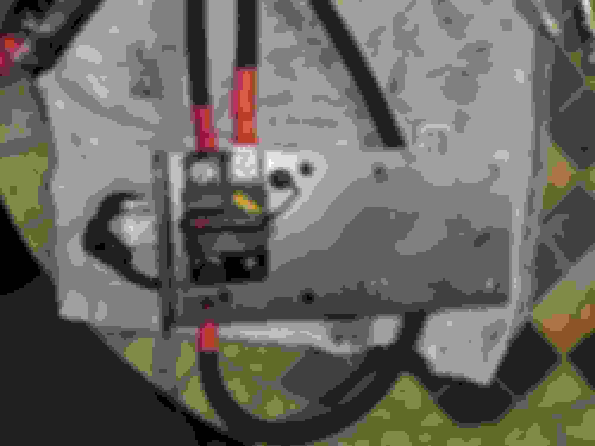
I used a Bluesea automatic charge relay . It connects and disconnects the house to aux batteries depending on voltage it sees. and it comes with a remote toggle switch for manual operation. The accessory tray is from C4 fabrication, the one made for a 5th gen 4runner. It fits in the GX. I mounted the ACR on the underside of the tray, and luckily the mount holes lined up to a mounting hole for the AUX batt circuit breaker so that setup worked out for me. I have room to add a relay box in the future for more accessories.
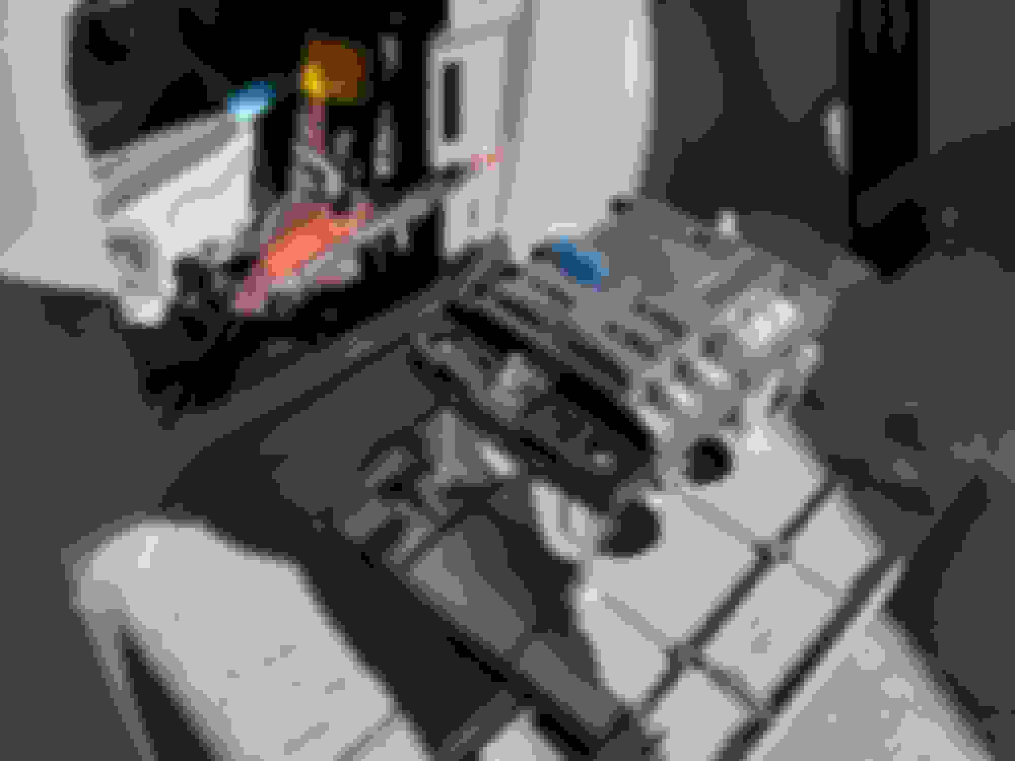
With the fuses and all the wiring in. Still have easy access to oem fuse box
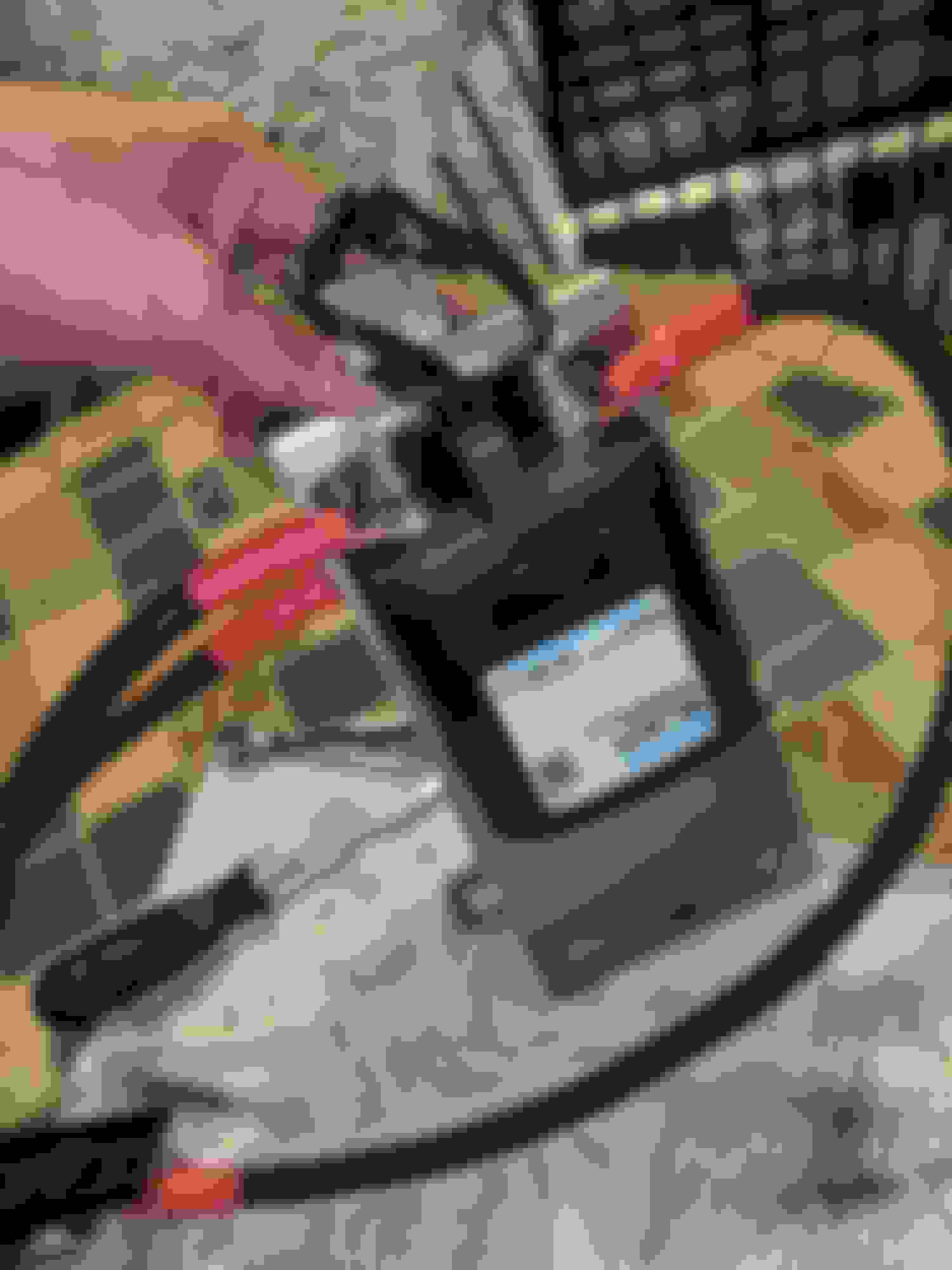
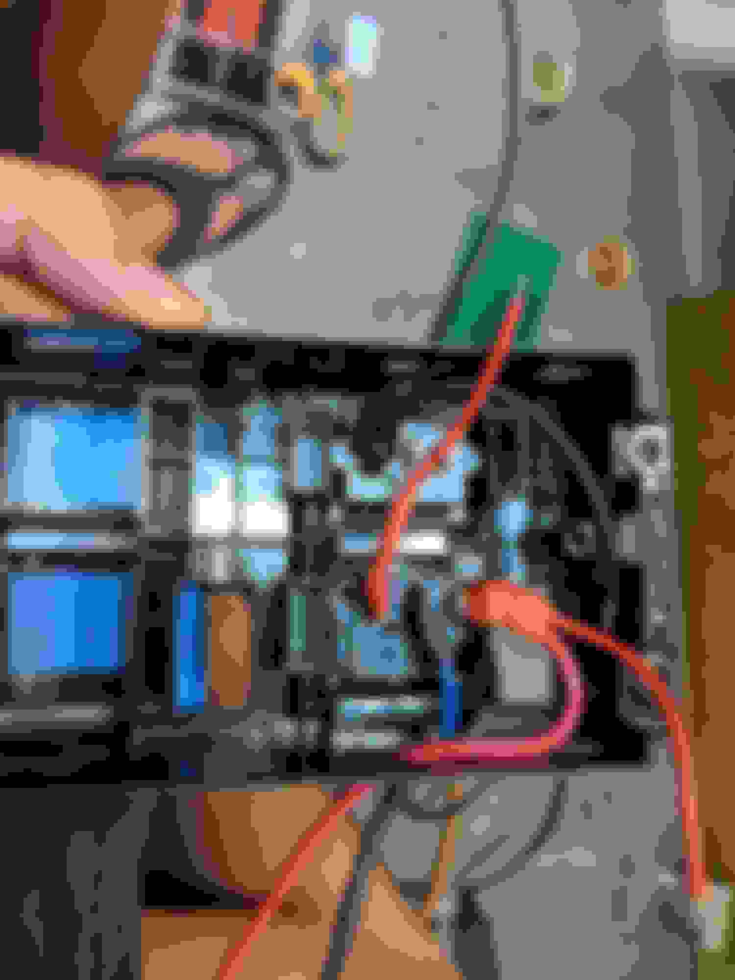
The Alt-S fuse trick. this tells the alternator what voltage to output. I added a zener diode after the fuse to drop the voltage the alternator sees by .6v-ish which will raise the output of the alternator by the same amount to compensate. the AGM Odessey batteries I used has a recommended charge voltage of 14.8v max. I get 13.8-14.4v after adding the diode. I hacked up an add-a-fuse thing. the alt-s fuse is below the white 25a fuse in the middle of the relay box
Didn't take any pics of the cable routed to the rear of the car, but I went along the frame rails and used zip ties. It goes up a grommet that sits below the left 3rd row seat. stole this idea from another build thread I saw on i8mud forums
The rear fuse block is mounted behind this panel. Couldn't find a flat spot to put it on near the oem jack, and personally I think this was a pretty slick idea. I may patent it. the whole panel can be quickly turned off with a switch. The usb ports will have some draw if left on
after adding crawl control, I had 2 non functional switches in the middle console. I used those spaces for the acr control and voltmeter. It was not easy to get in. I got a cheap dremel imitation tool from amazon and went to town on it
bonus pics!
That's all folks. I hope you enjoyed it
Edit: I actually used a rectifier diode. Part 1n4007
Pics might need to be re-shared out of Google Photos. I notice links are public versions that you can easily view on a Google Photos album using the Developer tools of Chrome. I haven't checked with one of my IOS devices but OS X can't render the image URLs either.
Super cool. Thanks for sharing. What's your total Ah with this setup? also, did you consider a dcdc charger? I think my issue is I am committed to my 125Ah agm that I already own. I may take the plunge and do a dual pc1200 like you at some point.
do you have the diode part number? also, why was a zener used instead of a normal standard rectifier? Im trying to understand when there would be a reverse bias and what the voltage would be used.
a zener can work, and does the same as a standard except when reverse biasing, and im not sure when this would reverse bias.
Super cool. Thanks for sharing. What's your total Ah with this setup? also, did you consider a dcdc charger? I think my issue is I am committed to my 125Ah agm that I already own. I may take the plunge and do a dual pc1200 like you at some point.
Those 2 little ones are 46ahr apiece if I remember right. I was afraid DCDC chargers would charge too slow and leave me with unfully charged batteries when I get to camp if I made a prior stop not far from camp. And the high output ones are too expensive. The beefy charge relay should take everything the alternator throws at it. If I used a lead acid and lithium combo I would reap more benefit from a DCDC charger. I would then be able to have the lithium in the back somewhere because DCDC charger won't care about the distance as much. If you had 2 different battery types or batteries far apart think DCDC chargers makes more sense. The Redarc unit is very nice
do you have the diode part number? also, why was a zener used instead of a normal standard rectifier? Im trying to understand when there would be a reverse bias and what the voltage would be used.
a zener can work, and does the same as a standard except when reverse biasing, and im not sure when this would reverse bias.
Oh you're right I've been calling it zener but they're regular rectifier diodes. 1n4007 is the part number, you can find them just about anywhere. You can use either in this case, you're just taking advantage of the negative side effect of the diode which is the voltage drop.
I wander how much the OEM battery weighs .... cause you replaced it with 76 lbs worth of battery on the same spot. Not sure that area is designed for that heavy of a dynamic load...other Yota 4x4's have been known to crack with similar configurations and any sort of off-roading or bumpy roads.

 11-28-19, 01:04 PM