Pics of my '06 IS250 with 2011MY headlights w/ LED Strip
 02-28-12, 07:51 PM
#436

I still like this solution for the AFS blinking.
Do you mean this projector? 
^ I was even lazier...put the tape right on top of the cluster LMFAO...god I'm lazy. I'll do something about it one day.
I didn't even have to remove the entire bumper to install them either. Thanks again for all of the helpful info in this thread.
Here are a couple pics at the car wash got her all prettied up since it rained during my install of them yesterday. I LOVE these headlights. The wife does too.

Uploaded with ImageShack.us

Uploaded with ImageShack.us
Last edited by Sango; 02-28-12 at 07:57 PM.
 02-29-12, 07:05 AM
#437
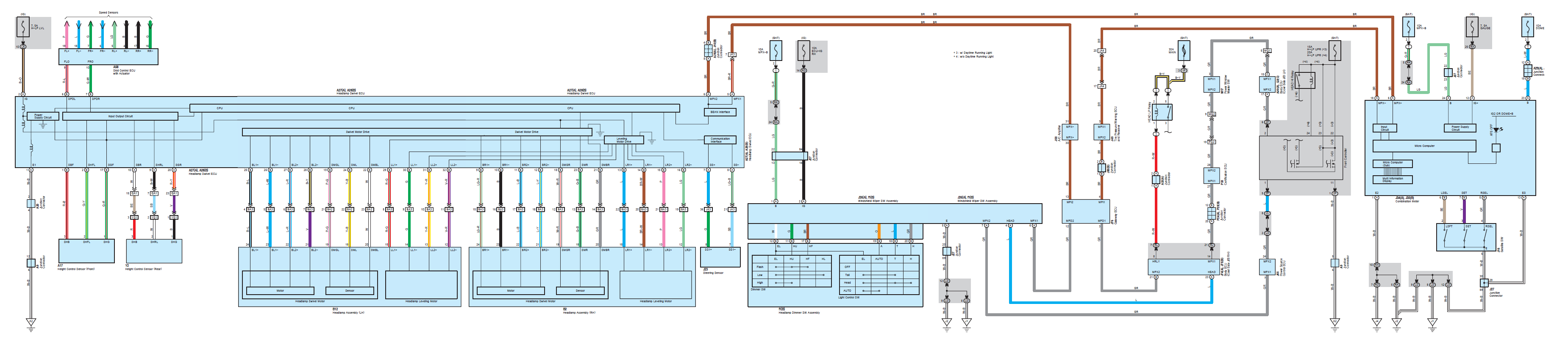
Obtain a 2011-12 leveling ECU and replace your AFS ECU with it. This isn't a simple swap as the connectors are different and a couple of wiring changes exist. The AFS ECU had a BEAN interface to the body ECU, while the Leveling ECU does not. The only thing this seems to really affect if you did this swap is that for some reason the 2011+ ECU gets an alternator signal (CHG-) from the body ECU, it only operates the leveling system when the engine is running, but that would need to be tapped in from somewhere else. It also expects a low beam signal from the body ECU for when the low beams are on (B2).
As far as I can tell, these are the parts you'd need:
One ECU:
89960-53040 - ISx50 RWD Sedan Leveling ECU
89960-53050 - ISx50 AWD Sedan Leveling ECU
89960-53080 - IS F Leveling ECU
89960-53100 - ISx50C Leveling ECU
And:
90980-12422 - Leveling ECU Connector
82998-24290 - Leveling ECU Connector Terminals (Qty: 15)
On your new connector (90980-12422) you will do the following:
Pin 1: Ground, Take Pin 1 out of the smaller 20-pin AFS ECU connector and insert it here.
Pin 5: Speed SPDL, Take Pin 6 out of the larger 32-pin AFS ECU connector and change out the terminal for one of the new ones, then insert it here.
Pin 6: Speed SPDR, Take Pin 7 out of the larger 32-pin AFS ECU connector and change out the terminal for one of the new ones, then insert it here.
Pin 7: Low Beam Trigger, Using one of your new terminals, splice this into the red/white wire coming out of Pin 2 on 22-pin junction connector A33 (RH kick panel)
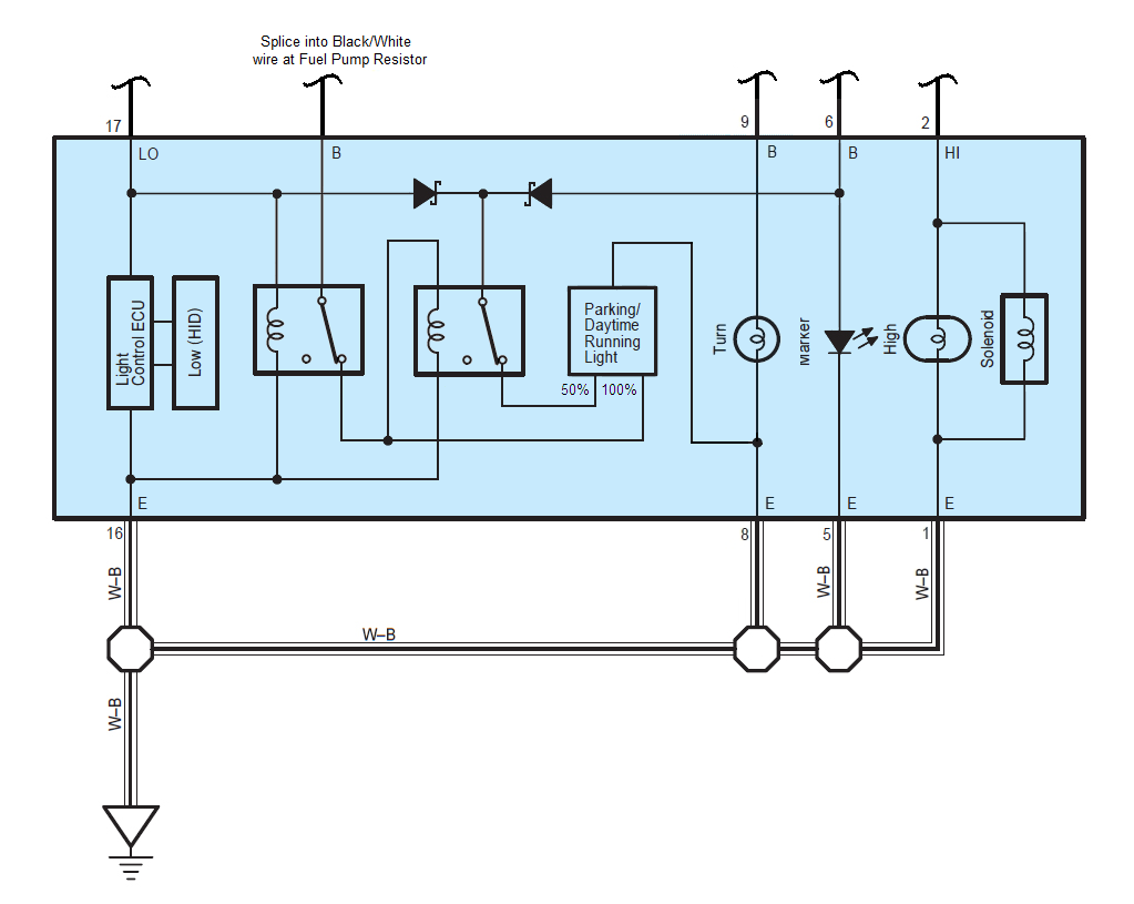
Pin 8: Alternator Charge Trigger, this should be +12V when the engine is running, 0V when the engine is off, ignition switch on. Not sure on a closer place to tap into, but you'll use one of your new terminals and tap into a wire with these characteristics. The easiest spot I can think of is the black/white wire going to the fuel pump resistor on the RH fender apron in the engine bay. (Alternatively, you could just tap this into Pin 1, and let it perform leveling even without the engine running).
Pin 9: RH Motor LR2-, Take Pin 16 out of the larger 32-pin AFS ECU connector and change out the terminal for one of the new ones, then insert it here.
Pin 10: RH Motor LR2+, Take Pin 15 out of the larger 32-pin AFS ECU connector and change out the terminal for one of the new ones, then insert it here.
Pin 11: RH Motor LR1-, Take Pin 14 out of the larger 32-pin AFS ECU connector and change out the terminal for one of the new ones, then insert it here.
Pin 12: RH Motor LR1+, Take Pin 13 out of the larger 32-pin AFS ECU connector and change out the terminal for one of the new ones, then insert it here.
Pin 14: +12V Power, Take Pin 2 out of the smaller 20-pin AFS ECU connector and insert it here.
Pin 16: Front Sensor SGF, Take Pin 17 out of the larger 32-pin AFS ECU connector and change out the terminal for one of the new ones, then insert it here.
Pin 17: Rear Sensor SGR, Take Pin 11 out of the smaller 20-pin AFS ECU connector and insert it here.
Pin 18: Front Sensor SHFL, Take Pin 2 out of the larger 32-pin AFS ECU connector and change out the terminal for one of the new ones, then insert it here.
Pin 19: Rear Sensor SHRL, Take Pin 9 out of the smaller 20-pin AFS ECU connector and insert it here.
Pin 20: Front Sensor SBF, Take Pin 1 out of the larger 32-pin AFS ECU connector and change out the terminal for one of the new ones, then insert it here.
Pin 21: Rear Sensor SBR, Take Pin 10 out of the smaller 20-pin AFS ECU connector and insert it here.
Pin 28: LH Motor LL2-, Take Pin 32 out of the larger 32-pin AFS ECU connector and change out the terminal for one of the new ones, then insert it here.
Pin 29: LH Motor LL2+, Take Pin 31 out of the larger 32-pin AFS ECU connector and change out the terminal for one of the new ones, then insert it here.
Pin 30: LH Motor LL1-, Take Pin 30 out of the larger 32-pin AFS ECU connector and change out the terminal for one of the new ones, then insert it here.
Pin 31:LH Motor LL1+, Take Pin 29 out of the larger 32-pin AFS ECU connector and change out the terminal for one of the new ones, then insert it here.
This is quite an involved process, but I think it should take care of everything and get it working just like the 2011-12's. It would have been nicer if both AFS ECU connectors used the same terminal type as the Leveling ECU connector, but only the smaller connector does. The larger AFS ECU connector uses an older style pin.
Not sure if anyone wants to try tackling this though. I mean if it was my car, I probably would, but it's an involved process for sure, especially when you can tape the light, haha.
Jeff
As far as I can tell, these are the parts you'd need:
One ECU:
89960-53040 - ISx50 RWD Sedan Leveling ECU
89960-53050 - ISx50 AWD Sedan Leveling ECU
89960-53080 - IS F Leveling ECU
89960-53100 - ISx50C Leveling ECU
And:
90980-12422 - Leveling ECU Connector
82998-24290 - Leveling ECU Connector Terminals (Qty: 15)
On your new connector (90980-12422) you will do the following:
Pin 1: Ground, Take Pin 1 out of the smaller 20-pin AFS ECU connector and insert it here.
Pin 5: Speed SPDL, Take Pin 6 out of the larger 32-pin AFS ECU connector and change out the terminal for one of the new ones, then insert it here.
Pin 6: Speed SPDR, Take Pin 7 out of the larger 32-pin AFS ECU connector and change out the terminal for one of the new ones, then insert it here.
Pin 7: Low Beam Trigger, Using one of your new terminals, splice this into the red/white wire coming out of Pin 2 on 22-pin junction connector A33 (RH kick panel)
Pin 8: Alternator Charge Trigger, this should be +12V when the engine is running, 0V when the engine is off, ignition switch on. Not sure on a closer place to tap into, but you'll use one of your new terminals and tap into a wire with these characteristics. The easiest spot I can think of is the black/white wire going to the fuel pump resistor on the RH fender apron in the engine bay. (Alternatively, you could just tap this into Pin 1, and let it perform leveling even without the engine running).
Pin 9: RH Motor LR2-, Take Pin 16 out of the larger 32-pin AFS ECU connector and change out the terminal for one of the new ones, then insert it here.
Pin 10: RH Motor LR2+, Take Pin 15 out of the larger 32-pin AFS ECU connector and change out the terminal for one of the new ones, then insert it here.
Pin 11: RH Motor LR1-, Take Pin 14 out of the larger 32-pin AFS ECU connector and change out the terminal for one of the new ones, then insert it here.
Pin 12: RH Motor LR1+, Take Pin 13 out of the larger 32-pin AFS ECU connector and change out the terminal for one of the new ones, then insert it here.
Pin 14: +12V Power, Take Pin 2 out of the smaller 20-pin AFS ECU connector and insert it here.
Pin 16: Front Sensor SGF, Take Pin 17 out of the larger 32-pin AFS ECU connector and change out the terminal for one of the new ones, then insert it here.
Pin 17: Rear Sensor SGR, Take Pin 11 out of the smaller 20-pin AFS ECU connector and insert it here.
Pin 18: Front Sensor SHFL, Take Pin 2 out of the larger 32-pin AFS ECU connector and change out the terminal for one of the new ones, then insert it here.
Pin 19: Rear Sensor SHRL, Take Pin 9 out of the smaller 20-pin AFS ECU connector and insert it here.
Pin 20: Front Sensor SBF, Take Pin 1 out of the larger 32-pin AFS ECU connector and change out the terminal for one of the new ones, then insert it here.
Pin 21: Rear Sensor SBR, Take Pin 10 out of the smaller 20-pin AFS ECU connector and insert it here.
Pin 28: LH Motor LL2-, Take Pin 32 out of the larger 32-pin AFS ECU connector and change out the terminal for one of the new ones, then insert it here.
Pin 29: LH Motor LL2+, Take Pin 31 out of the larger 32-pin AFS ECU connector and change out the terminal for one of the new ones, then insert it here.
Pin 30: LH Motor LL1-, Take Pin 30 out of the larger 32-pin AFS ECU connector and change out the terminal for one of the new ones, then insert it here.
Pin 31:LH Motor LL1+, Take Pin 29 out of the larger 32-pin AFS ECU connector and change out the terminal for one of the new ones, then insert it here.
This is quite an involved process, but I think it should take care of everything and get it working just like the 2011-12's. It would have been nicer if both AFS ECU connectors used the same terminal type as the Leveling ECU connector, but only the smaller connector does. The larger AFS ECU connector uses an older style pin.
Not sure if anyone wants to try tackling this though. I mean if it was my car, I probably would, but it's an involved process for sure, especially when you can tape the light, haha.
Jeff
Jeff
02-29-12, 02:14 PM
#439
if the motor has 4 wires is assumed that a pair is for a movement in one direction (I do not know if it's up or down or left or right) and another pair for another dedireccion movement,
the thing is that if motors have magnetic fields that are coil, which have a impedanza which is equal to an ohmic resistance.
with a multimeter you could measure these fields impedanzia dc motor, the ohmic value multiplied by 2 = x.
then look for 2 resitencia equal to the value of x, with a wattage of 5W, and connect the connector pins B corresponding to the AFS as if trying to lie to conrol the AFS.
is an opinion guys, maybe this could help someone find the way and try to tell the AFS ECU that everything is fine and no more blinking occurs (my 250 is not equipped with AFS) thanks ..
02-29-12, 07:08 PM
#440
The stepper motor probably isn't what's causing the AFS light. There is also a sensor inside that it uses to detect rotational position. I believe that is what you'd have to fake, or possibly both. Faking the stepper motor would likely be relatively easy (resistors in place of the coils), but the sensor would likely be harder. Could potentially mount some AFS assemblies and wire them in and just let them do their thing, but it seems like a lot of work, lol.
Jeff
Jeff

 02-29-12, 10:32 PM
#445
Thanks Jeff !!!!I think Swlvel ECU generates a digital signal x to the sensor, this is controlled by the motor, modifying the signal in time and returns to the interfaces, as well as the CPU is known about the movomientos ..
Now we could get started by connecting a 10 k ohms resitencia between pins 12 and 13, BA3, and a 10 k ohms (1/4w) between pins 21 and 22 I think BA2.yo BA2 and BA3 are in the driver, we have to ask Jeff
Now we could get started by connecting a 10 k ohms resitencia between pins 12 and 13, BA3, and a 10 k ohms (1/4w) between pins 21 and 22 I think BA2.yo BA2 and BA3 are in the driver, we have to ask Jeff
Last edited by jgarrido; 03-01-12 at 10:52 AM.

 03-02-12, 11:20 PM
#447
Finally, adding some much needed "Light" to this thread....... !!!
Some things to know... If you buy a pre-made kit, you don't have to deal with any of this stuff...
The only thing you have to do is swap the Flasher Relay cube, which sits in the space above the Brake & Gas pedal under the dash.
If you have an IS with AFS, you will indeed get a flashing AFS indicator light.. If you have an IS with just the Halogen headlights, you will not have a flashing AFS indicator.
So far the only known way to stop the blinking AFS light, is to crack open the cluster and block the light that passes through that area with something Black.
Also, the bumper brackets that screw into the bottom of the headlights, will need slight modifications to be attached to the new MY2011 lights.. Basically dremeling some of it off that sits over the LED wire dome cap on the underside of the housings.
But still, only 2 screws will line up after that.
I tried the new step mentioned, of only swapping the GREEN wire location, that DID NOT work on my 2008 IS-F.
So I went with what "thinktwice" originally did..
I snipped the thinner solid red wire, then tapped it into the Black & White wire underneath it..
Then I changed the pin location of the Green Wire to the empty spot... Done.!!
I also tested the Solid Black wire and Solid Green wire to confirm the differences between the 50% & 100% brightness of the LED strip.
I went with 100% power.
Also, the new Flasher relay needed is indeed Lexus / Toyota Part # 81980-06020
That takes all of about 5 minutes to find unplug & replug the new unit.
I only got pics of the Flasher swap so far.. (I was in a rush)
I will try to update this post in the near future with how the wiring looks before and after the slight modification done to the primary male plug connector on the new headlight.
Thanks for all input in this thread..!!
Regards,
~ Joe Z
Picture 1 = NEW Relay
Picture 2 = NEW Relay and Old Relay, side-by-side
Picture 3 = Old Relay & Location (mine was green & blue)
Picture 4 = New Relay & Location (brown & black)
Picture 5 = Pearl Yellow LFA #P014 & MY IS-F
Can you confirm these are the extra steps to make it "plug & play"
Dremel bumper guard
Removal of existing ballast
Relay flasher replacement
Bolt on only 4 of 6 bolts
Thanks!
03-22-12, 11:39 PM
#448
Okay, so after thinking about this, and the possibility of using transistors instead of relays, etc. I figured it's probably easiest to just post it with the relays. If anyone wants to use a transistor, the MOSFET IRF5305 transistor can be used for a normally closed setup like this, and should be able to handle the current without issue. I swapped out the diodes in the diagram for schottky diodes as they will have a lower forward voltage drop (basically insignificant to this application) than a regular diode. I figure with 12 LED's per side, you're looking at around 400mA, so it's pretty small current for these LED's.
Verbose functionality listing with this wiring:
Ignition Off, Headlight Switch Off: All Off
Ignition Off, Headlight Switch Flash: LED's at 50%, Low Beams + High Beams On
Ignition Off, Headlight Switch 1 Click: LED's at 50%, Markers On
Ignition Off, Headlight Switch 2 Clicks: LED's at 50%, Markers On, Low Beams On
Ignition Off, Headlight Switch 2 Clicks, Pushed Forward: LED's at 50%, Markers On, Low Beams + High Beams On
Ignition Off, Headlight Switch 3 Clicks: All Off
Ignition On, Headlight Switch Off: LED's at 100%, All Others Off
Ignition On, Headlight Switch Flash: LED's at 50%, Low Beams + High Beams On
Ignition On, Headlight Switch 1 Click: LED's at 100%, Markers On
Ignition On, Headlight Switch 2 Clicks: LED's at 50%, Markers On, Low Beams On
Ignition On, Headlight Switch 2 Clicks, Pushed Forward: LED's at 50%, Markers On, Low Beams + High Beams On
Ignition On, Headlight Switch 3 Clicks, Daylight: LED's at 100%, All Others Off
Ignition On, Headlight Switch 3 Clicks, Dark: LED's at 50%, Markers On, Low Beams On
Ignition On, Headlight Switch 3 Clicks, Dark, Pushed Forward: LED's at 50%, Markers On, Low Beams + High Beams On
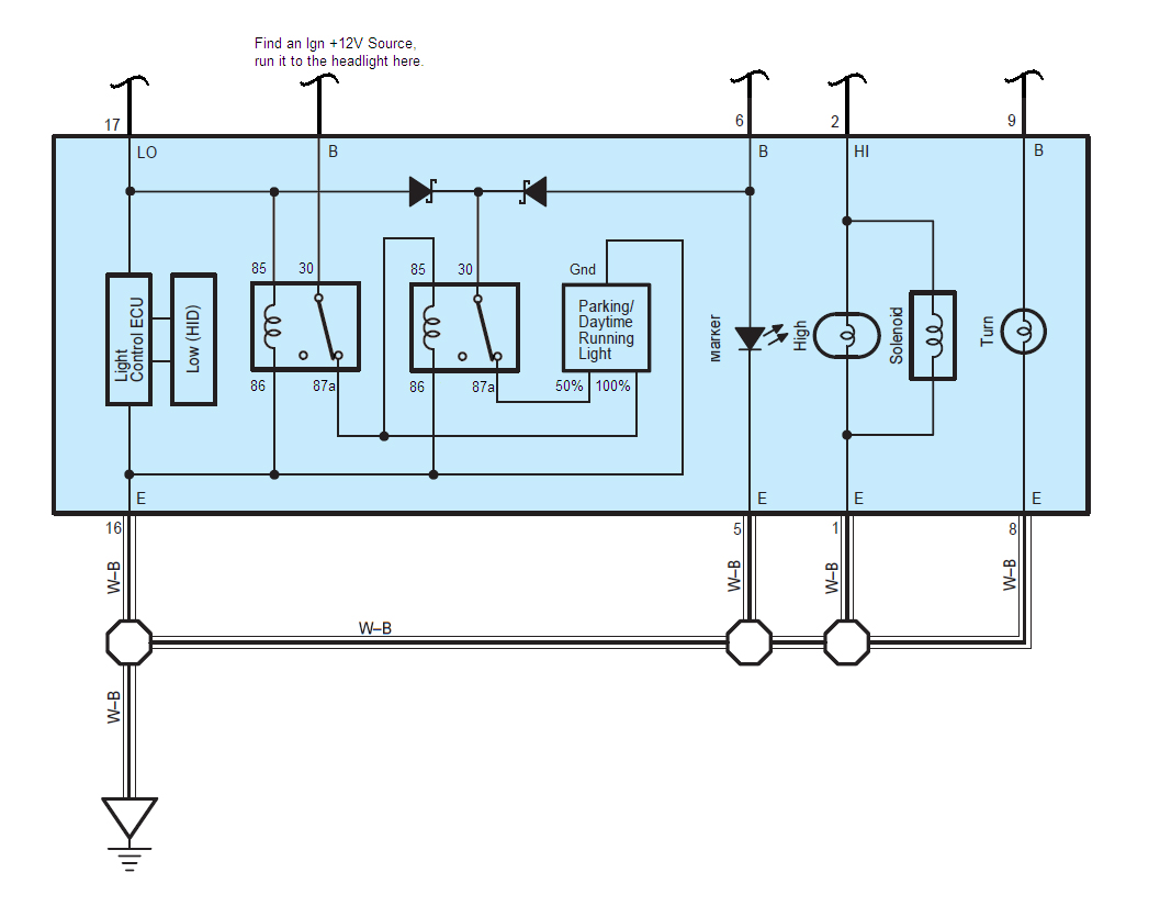
Okay, I think that's about the best I can do. I've spent too much time on this today, haha.
EDIT: I'd also like to say that it is certainly possible to do this in the car's wiring and just wire it into the correct spots on the headlight connector. That way you only need 2 diodes and 2 relays instead of 4 diodes and 4 relays (2 per side). It's just going to depend on whether or not you want to mess with the car's wiring more, or the headlight's wiring more.
Jeff
Verbose functionality listing with this wiring:
Ignition Off, Headlight Switch Off: All Off
Ignition Off, Headlight Switch Flash: LED's at 50%, Low Beams + High Beams On
Ignition Off, Headlight Switch 1 Click: LED's at 50%, Markers On
Ignition Off, Headlight Switch 2 Clicks: LED's at 50%, Markers On, Low Beams On
Ignition Off, Headlight Switch 2 Clicks, Pushed Forward: LED's at 50%, Markers On, Low Beams + High Beams On
Ignition Off, Headlight Switch 3 Clicks: All Off
Ignition On, Headlight Switch Off: LED's at 100%, All Others Off
Ignition On, Headlight Switch Flash: LED's at 50%, Low Beams + High Beams On
Ignition On, Headlight Switch 1 Click: LED's at 100%, Markers On
Ignition On, Headlight Switch 2 Clicks: LED's at 50%, Markers On, Low Beams On
Ignition On, Headlight Switch 2 Clicks, Pushed Forward: LED's at 50%, Markers On, Low Beams + High Beams On
Ignition On, Headlight Switch 3 Clicks, Daylight: LED's at 100%, All Others Off
Ignition On, Headlight Switch 3 Clicks, Dark: LED's at 50%, Markers On, Low Beams On
Ignition On, Headlight Switch 3 Clicks, Dark, Pushed Forward: LED's at 50%, Markers On, Low Beams + High Beams On
Okay, I think that's about the best I can do. I've spent too much time on this today, haha.
EDIT: I'd also like to say that it is certainly possible to do this in the car's wiring and just wire it into the correct spots on the headlight connector. That way you only need 2 diodes and 2 relays instead of 4 diodes and 4 relays (2 per side). It's just going to depend on whether or not you want to mess with the car's wiring more, or the headlight's wiring more.
Jeff