When you click on links to various merchants on this site and make a purchase, this can result in this site earning a commission. Affiliate programs and affiliations include, but are not limited to, the eBay Partner Network.
MPX Override for Fog lights when running lights are on? Help
All, there are several threads on hacking the fog light so one has options to turn them on without the headlights. That said, I do not want wires through the cabin, extra switches, lights that stay on because I forgot to turn them off. Any of that....
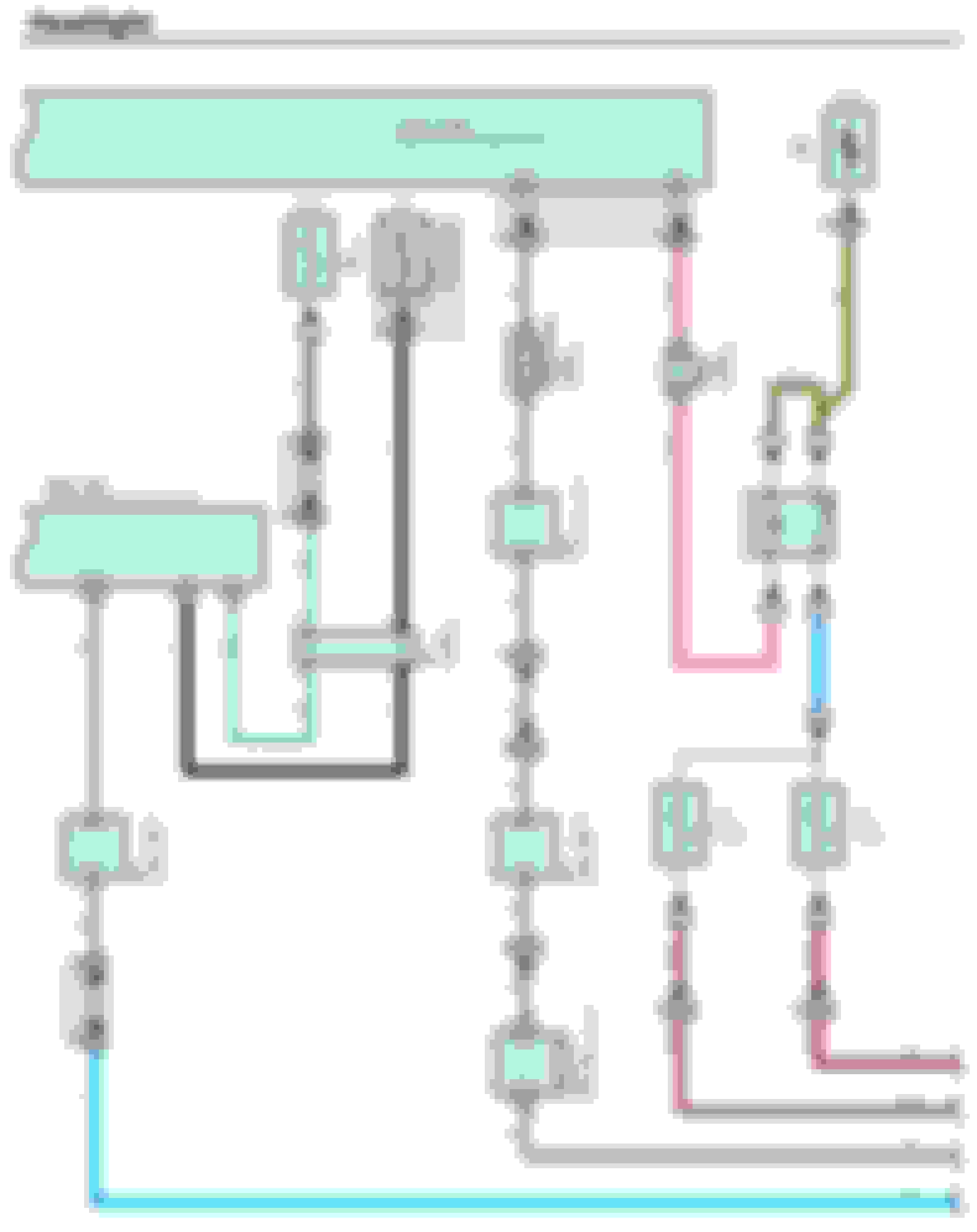
The problem is the stalk switch goes right to a data bus. From the data bus it goes to the BCM (and other places?) under the hood to the left front fuse box MPX relay box where the addressed data is enabled by the BCM to turn on the Fog lights. All of that said, there must be a better way than hacking a wires through the cab, to the stalk, to a switch and all of that.
So, anyone have any new ideas on how to resolve this? Anyone know how we can address items on the bus? I used to have access to an oscilloscope capable of reading I2C data and some forms of CAN bus data. This may be an option but we we need a plan. Maybe apply some TTL logic to this and do an OR statement. I'm open... If only the MPX data sent a signal to the Front Controller MPX Fuse Panel where the Fog light relay is. But no. the US production BCM does not allow this as best I can tell.
All of this because of the Morimoto LED Fog lights installed this weekend. Which are pretty nice for filling in the area alongside the car and just in front of it.
LED Fogs installed!
Originally Posted by 2013FSport
Done... now for some nighttime adjustments. Thankfully yoda plastic has a hole for this.... albeit a PITA to find the adjuster when needed.
As usual, phone does the color no justice. But both are 55000k now.
If anyone does this the white black wire is ground as you assemble the connector yourself.
white/black trace --> to LED black wire
My goal is this; only enable fogs when the running lights are one.
Retain the OEM stalk switch.
Fogs turn off with running lights, head lights.
There are digital options to take data from the running lights and get it forward to the fogs but most of those options ignore the OEM fog light switch.
Anyone know anything about the protocol used to address items on the bus?
Is it possible to take another MPX lighting box and use it to
This good info but I would like to avoid adultrating anything in the cabin.
I will admit I have not done enough research but if one were to simply ad this wire from the stalk and run it to our left side fuse panel, open the control panel box and insert a diode between our new wire and the relay, one would have manual control over the fog lights and the cars MPX addressing communications would not know the difference. That said we still need to address turning the system off when the ignition is off. Which it may do using that method for us with that mod but I haven't tested it.
Again, my goal would be to enable power to the fogs whenever the running lights are on and have control over them at the stalk so they are independent of the running lights. I'm guessing one will have to tap the stalk to achieve this but that will be a last resort.
1. MPX (MULTIPLEX COMMUNICATION NETWORK)
The MPX connects the ECUs of this vehicle and uses an ON-OFF signal (binary 0 and 1) to communicate with each ECU. The ECU operates the actuator based on the other ECU information. For example, the ECM (PCM) allows the engine to start based on the transponder key ECU information. The MPX consists of 3 networks: AVCLAN (Audio Visual Communication Local Area Network), BEAN (Body Electronics Area Network) and CAN (Controller Area Network). The gateway ECU is connected to and coordinates communication between the 3 networks.
2. AVC-LAN (AUDIO VISUAL COMMUNICATION LOCAL AREA NETWORK)
The audio/visual system uses the AVC-LAN. The master ECU is connected to gateway ECU and sends the signal to the other ECUs. The wire harness is a twisted twin wire covered with the insulation. One wire is used for the positive voltage and the other wire is used for the negative voltage.
AVC-LAN: Twisted twin wire; Maximum 17,800 bps; Data Length = 0 to 32 byte
3. BEAN (BODY ELECTRONICS AREA NETWORK)
The body electrical system uses the BEAN. The ECUs are connected to the gateway ECU like a daisy chain. This maintains the communication if the wire harness has an open circuit. The wire harness is a signal core line covered with insulation.
BEAN: Single line; Maximum 10,000 bps; Data length 1 to 11 byte
4. CAN (COMMUNICATION AREA NETWORK)
The powertrain and chassis system use the CAN. The CAN circuit has 2 master ECUs. One master ECU is connected to the other master ECU by the main wire. The gateway ECU and other ECUs are connected to the main wire by the branch wire through the junction connector(s). The wire harness is a twisted twin wire covered with insulation. One wire (CANL) is 1.5 to 2.5 volts and the other wire (CANH) is 2.5 to 3.5 volts.
CAN: Twisted twin wire; 500,000 bps* (Maximum 1 Mbps); Data Length = 1 to 8 byte
FWIW: Both AVC-LAN and BEAN are proprietary Toyota protocols. CAN is ISO 15765-4.
So as not to cause CR issues, anyone wanting more
details can look here.... BEAN 970297 This explains BEAN as it was developed for the LS400 in 1995 to reduce the volume of wires needed to run a luxury car.
My goal is this; only enable fogs when the running lights are one.
Retain the OEM stalk switch.
Fogs turn off with running lights, head lights.
You can get a relay to turn on the fog lights when there is power to the running lights. You need to tap a +12V fuse in the hood and the running light wires.
Jeff,
An observation when switching the lights from off to on is that a relay is activated near the steering wheel area. That said, I can not find this relay in the schematic. Any chance you have some insight on this or have stumbled upon in during your digging into the dash area?
Thanks in advance.
EDIT:
Unless this is it here but it seems like the wrong place and I don't see why they would have 30 Amps available in the cabin. That doesn't make sense to me. My guess is it is hidden inside of some other module (the relay I hear clicking in the dash)? But IDK.
I suspect the relay you're hearing is the TAIL relay in the LH dash junction block, but I'm not 100% sure. Do you hear it when you go from tail lights to headlights or only from off to tail lights?
I suspect the relay you're hearing is the TAIL relay in the LH dash junction block, but I'm not 100% sure. Do you hear it when you go from tail lights to headlights or only from off to tail lights?
Jeff
It is left of the wheel and from off to tail on/tail off. Not impacted by head light on/off.
I bring that up as I was not aware of there being a relay in the cabin for exterior lighting.
Now if only I could find life from the fog light switch outside of the cabin but it likely has some logic like"head light AND fog light switches" must be on. The question is; where is this logic? In a lighting module or the BCM?
Thanks Jeff.
The headlight and fog light control logic is split between programming in two control ECU's, the body ECU in the interior LH junction block and the front controller in the LH engine bay relay block (which also houses the fuse and relay).
I highly suspect that the logic is in the front controller based on my previous research and reading. I also believe that not all countries limit fog light usage to requiring the headlights. For a 2011-2013 ISx50 with factory HID's, I suspect that 89211-53020 would be the part number for a front controller that allows full fog light control. I have never tried this, so use that information as you see fit, haha.
Jeff
LOL! ^^ Rarely do we see you make statements like this!
So, maybe I need to do more digging and open the little relay/fuse/computer compartment and see if switched Fog Lamp control is in their?
Following your lead; I would be a little skeptical of tossing a foreigner in there as I don't need wire smoke! It's not that cold out yet!
I've opened the front controller before and the PCB and components are fully potted in. It would be very difficult to make changes. :\
As far as swapping the part, there isn't much chance that you'd actually damage anything, I just don't know if you'd actually get the functionality you're looking for, so it may be a waste of money, haha.
This is definitely doable with relays, diodes, and few Add-a-circuit Fuse TAP. All signal and power source needed can be tapped in the engine left relay box. No need to run any wire into the cabin. It doesn't 100% replicate the factory behavior, but close enough. The hardest part will be fitting those relays inside the fuse box. If I were to do this mod, I would have put the relays inside a small box and mount it outside the relay box, then run wire back into the relay box for the connections.
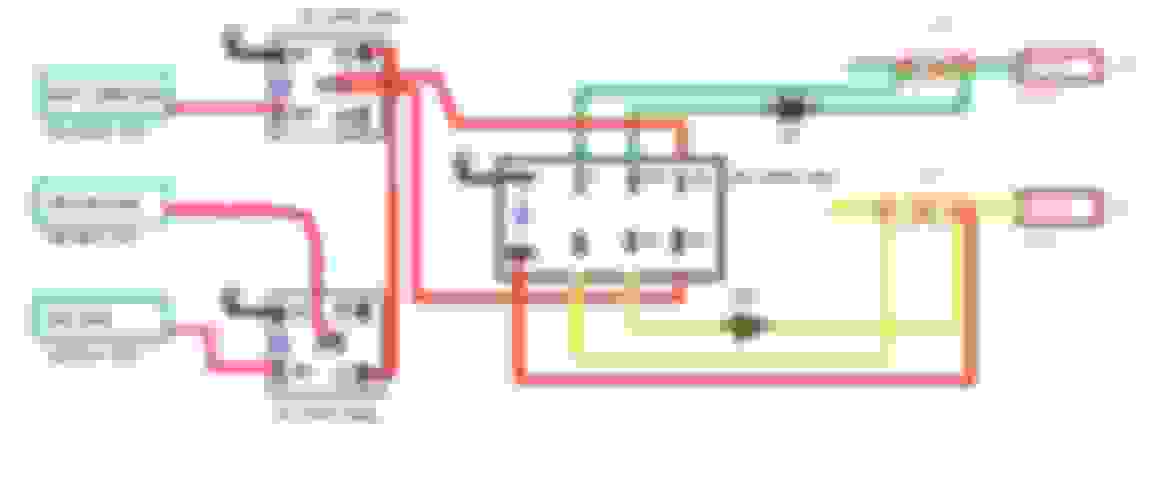
You don't need to access the digital fog light signal. Just need to tap into the fog light output wires on the front controller to manipulate the way fog light gets its power using relays. This is how I would wire it up in a 2006 is250:
1. R1 relay turns on power from the FOG light fuse in ACC
2. R2 relay cuts power to the FOG light whenever low beam is turned on
3. R3 relay allows the factory stalk switch to turn on the FOG light when low bean is on.

 11-24-19, 09:02 PM