
For discussion - Gear position indicator
 02-28-14 | 06:51 PM
#16

Thread Starter
Pole Position
Joined: Nov 2007
Posts: 324
Likes: 0
From: VN
OK, got some time today. first off, the mission is simple. in OBD1 plug under kick panel, driver's seat, there is a terminal named TT, when connect this terminal and E1 to a volt meter and run the car, voltage will vary according to gear position (see table in my very first post. So we just need to create something that reads voltage, "translate" into gear position, and display it to driver as 1,2,3, L3 (Lock-up), 4, L4 (lock-up)
To get the voltage readings and display gear position on 7 segment leds, I use arduino board. You can find more information about it on the website. in short, arduino board is produced for "everyone", who may or may not have deep knowledge about electronics, even dont know how to solder. believe it or not, I did this project completely solderless.
The board I use is Leonardo (i bought it for 25 bucks), but you can use any of them. However, to make it plug-and-play, you will need to find a board with compatible base shield available. please find more information about this on their website. Also, the code I use for this project is for Leonardo board, you may need to modify the code if you decide to use another board.
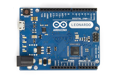
Leonardo seems a bit overkilled for this project so again, you can use any of them.
To display gear position, I use this 4 digit 7 segment led.

It costs me $20, you can buy it from here. The reason I use this module is that its Grove compatible allowing plug-and-play and number of required wires down from dozen to 4.
next is the Grove base shield. this is nothing but a board to make things really Plug-and-Play. I love it. cost is $9

I bought some Grove compatible cables as well, they sell pack of 5 for about $3

since the input voltage varies from 0 to 7 volts while input pins of Arduino board can take only 5 volts and below. so to read voltage over 5 volts, we need to create something called voltage divider. this is an easy thing by using 2 resisters. schemetics is as below

you can find more information there to use resisters of your choice or just follow what I use.
I use R1 = 10k ohm and R2 = 4.7k ohm
alternatively, you can buy $6 grove voltage divider, which will make things even easier

however, you will need to change the code if you use grove voltage divider. otherwise, readings will be wrong.
Thats about the parts. Next comes the code.
To get the voltage readings and display gear position on 7 segment leds, I use arduino board. You can find more information about it on the website. in short, arduino board is produced for "everyone", who may or may not have deep knowledge about electronics, even dont know how to solder. believe it or not, I did this project completely solderless.
The board I use is Leonardo (i bought it for 25 bucks), but you can use any of them. However, to make it plug-and-play, you will need to find a board with compatible base shield available. please find more information about this on their website. Also, the code I use for this project is for Leonardo board, you may need to modify the code if you decide to use another board.
Leonardo seems a bit overkilled for this project so again, you can use any of them.
To display gear position, I use this 4 digit 7 segment led.
It costs me $20, you can buy it from here. The reason I use this module is that its Grove compatible allowing plug-and-play and number of required wires down from dozen to 4.
next is the Grove base shield. this is nothing but a board to make things really Plug-and-Play. I love it. cost is $9
I bought some Grove compatible cables as well, they sell pack of 5 for about $3
since the input voltage varies from 0 to 7 volts while input pins of Arduino board can take only 5 volts and below. so to read voltage over 5 volts, we need to create something called voltage divider. this is an easy thing by using 2 resisters. schemetics is as below
you can find more information there to use resisters of your choice or just follow what I use.
I use R1 = 10k ohm and R2 = 4.7k ohm
alternatively, you can buy $6 grove voltage divider, which will make things even easier
however, you will need to change the code if you use grove voltage divider. otherwise, readings will be wrong.
Thats about the parts. Next comes the code.
Last edited by qha_vn; 03-01-14 at 09:32 PM.
02-28-14 | 08:23 PM
#17

Moderator
Joined: Aug 2011
Posts: 3,930
Likes: 925
From: Japan
We definitely need people like you in automobile repair industries, qha_vn. Many shop owners as well as mechanics don't understand electronics related affairs well enough and they always try to analyze and fix problems using their old ways that often mess things up. Even some People here and Dealers are so too, I find.
03-17-14 | 11:09 PM
#19
Thread Starter
Pole Position
Joined: Nov 2007
Posts: 324
Likes: 0
From: VN
Sorry for the delay. too busy recently. my project is still pending. test is still going on, appears to work perfectly so far.
this is the terminals TT (+) and E1 (-) you need to measure voltage change when car is running.

of note, when you turn key to ON, and engine is NOT started/ running. voltage on TT and E1 will vary from 0 to 8 volts when you gradually depress gas pedal.
this is the terminals TT (+) and E1 (-) you need to measure voltage change when car is running.
of note, when you turn key to ON, and engine is NOT started/ running. voltage on TT and E1 will vary from 0 to 8 volts when you gradually depress gas pedal.
Last edited by qha_vn; 03-18-14 at 12:05 AM.
03-18-14 | 12:29 AM
#20
Driver
Joined: Jul 2013
Posts: 131
Likes: 1
From: PA
This is great!  I LOVE what you did here. If I ever find the time, I'd love to do this mod but I would probably use a single digit white 7-segment display or find some type of a more modern looking display.
I would like you guys to figure out what other useful information we could display?
I love what you did with the arduino. I have a little experience with that micro-controller. I made a simple GUI based game for one of my classes with Matlab and the accelerometer add on. I have a lot more experience with the PsoC development board, however. I've been using is all of this past quarter at my university do make all types of neat things.
I agree with Yame, we need people with experience in electronics so that we can keep these cars going. It's better to figure out what really going on with your car than it is to just shotgun it with pats. (although regretfully I am a culprit of doing this occasionally!) qha_vn, I want to see more stuff like this! One thing I absolutely plan on doing, when I one day get the funds, is to do my own LED tail lights. Something like
 (they are to die for!.. mesmerizing)
I wonder if this guy used regular 3mm LEDs or if they are SMD's.
I LOVE what you did here. If I ever find the time, I'd love to do this mod but I would probably use a single digit white 7-segment display or find some type of a more modern looking display. I would like you guys to figure out what other useful information we could display?
I love what you did with the arduino. I have a little experience with that micro-controller. I made a simple GUI based game for one of my classes with Matlab and the accelerometer add on. I have a lot more experience with the PsoC development board, however. I've been using is all of this past quarter at my university do make all types of neat things.
I agree with Yame, we need people with experience in electronics so that we can keep these cars going. It's better to figure out what really going on with your car than it is to just shotgun it with pats. (although regretfully I am a culprit of doing this occasionally!) qha_vn, I want to see more stuff like this! One thing I absolutely plan on doing, when I one day get the funds, is to do my own LED tail lights. Something like
(they are to die for!.. mesmerizing)I wonder if this guy used regular 3mm LEDs or if they are SMD's.
Last edited by aomdedude1; 03-18-14 at 12:35 AM.
03-18-14 | 12:42 AM
#21
Driver
Joined: Jul 2013
Posts: 131
Likes: 1
From: PA
I love this! If only there was a way to incorporate an LCD that would display all this information into the OEM display in a way that mikes it look stock. I'm all over this idea with you!

... one mod I've been wanting to figure out is seeing if there was a way to interface with the wireless of TPMS sensors.. this might be very challenging, but it would be neat to have access to your tire pressures. Especially if your about to do a high speed blast!
03-18-14 | 03:52 AM
#22
Thread Starter
Pole Position
Joined: Nov 2007
Posts: 324
Likes: 0
From: VN
I "hacked" into the instrument cluster to make it OEM look (I hope so)
tools required. look very low tech isnt it

I identified a free slot in between the warning lights

front look

cut it down about 10mm

the led board seated perfectly in the cut out

from above

another angle

closer look

once the cut is perfect, I paint the hole black. must use masking tape and newspaper

I then use a black pen to "finetune" the paint job. as long as it is black and not glossy, you are fine.

Now use a gluegun to glue the board to the frame


here we go

front look

perfect fit

board is tried in

Now I need to cut the "lens". use a black pen to draw lines for cutting

closer look

use the dremel, cut your way little by little, dremel RPM should just be about 4k to 6k. faster rpm will melt plastic down

try it on

closer look

now plug in cable

board goes in

run final test to make sure it displays properly

the show is going on

tools required. look very low tech isnt it
I identified a free slot in between the warning lights
front look
cut it down about 10mm
the led board seated perfectly in the cut out
from above
another angle
closer look
once the cut is perfect, I paint the hole black. must use masking tape and newspaper
I then use a black pen to "finetune" the paint job. as long as it is black and not glossy, you are fine.
Now use a gluegun to glue the board to the frame
here we go
front look
perfect fit
board is tried in
Now I need to cut the "lens". use a black pen to draw lines for cutting
closer look
use the dremel, cut your way little by little, dremel RPM should just be about 4k to 6k. faster rpm will melt plastic down
try it on
closer look
now plug in cable
board goes in
run final test to make sure it displays properly
the show is going on
Last edited by qha_vn; 03-18-14 at 04:08 AM.

Thread
Thread Starter
Forum
Replies
Last Post
Lextrician
LS - 4th Gen (2007-2017)
3
07-08-14 08:07 AM