When you click on links to various merchants on this site and make a purchase, this can result in this site earning a commission. Affiliate programs and affiliations include, but are not limited to, the eBay Partner Network.
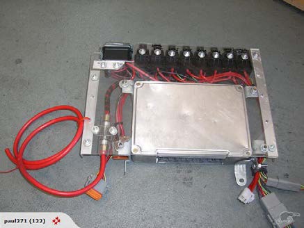
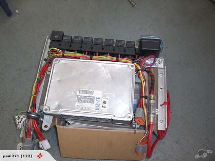
Below, pictures of a basic ECU board, made for a customer, to house the ECU and fuses, relays required to run all the electrics in a race car, Uses high quality electrical parts that cost about $500 on their own, could be created for less for a road car using off the shelf parts from nation wide electrical supply chains. The ecu is meant to be on the below side, with the top side in below photo. The relays outward as are the fuses. could be done differently
The concept of putting the ecu and relays and fuses related to the engine (and not the entire system as is the case here) stands useful. In high vibration environments soldier will break. If your running 1500hp, in a drag car, or more, then boards like this are a NO GO, you need to crimp and screw in each connection, same goes for trails trucks running 44's and being driving on the tar-sealed roads from time to time.
The board has a 'common earth rail' for all relays, to allow the coil in them to trip when power is applied to each one's switching side. There is also a separate Earth rail for ECU's two earth connection (E1 and E2) to prevent interference; for good measure. There is a tag, which holds the ecu?s loom as it comes in from the engine, there to take strain off the plugs and wiring when in place.
Allow an inch between ECU and relays, cables get larger than expected once all in place. The fuse box is from Hella about $136+gst, and you can get cheaper ones from supercheap that are good, I doubt you need a 12x fuse box, may only need 8 row one from s/cheap. ($21??). I had to remove the inner plate in the hella fusebox and solider a wire to the pole on each side of each fuse, not sure why they only had two circuits in it.
However it only had two electrical channels in (I make also of use of relays) not enough for the electrical system. I used a 80amp replay for the starter (factory spec), you don?t need that, 40amps is fine, but the extra is good. You don?t really need so many relays, chances are, you probably only need 6 relays.
Fuel pump,[/*]
Fuel injectors, (have constant power on IGN key position, earth is at the ecu for injection trigger, duty cycle is an ecu function),[/*]
Ignition/spark (goes to the igniter's and coil),[/*]
Fan or not,[/*]
Engine main ACC (power all the little stuff),[/*]
Starter solenoid 80am/40amp.[/*]
<p>
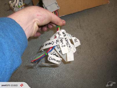
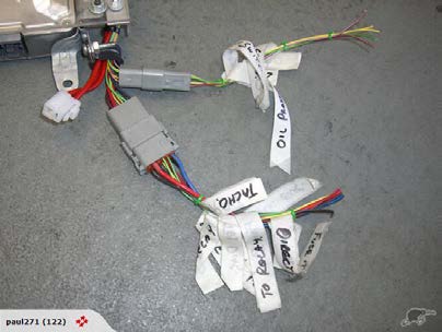
Three Plug bundles,
separate sensor outputs and basic power (style + quality + possible interference),[/*]
one for car side (inputs and outputs, e.g ignition and start), as well as ,[/*]
another for tacho, oil, water, idiot light (oil low), etc etc). As well as .. check engine/diag light,[/*]
goes to engine loom, blends into the engine harness,[/*]
the fourth bundle, which is not shown, is the actual loom which comes from the engine.[/*]
16- Swapping Between Series One and Series Two (non VVTI) engine
The front plugs at right next to the Diagnostic plug are configured differently, they will plug in fine. But the engine will not run, or even start.
The coil wires need to be swapped over.[/*]
So do the wires for the Crank Angle sensor.[/*]
Note: never make a change to your wiring without confirmed the accuracy of my information to your particular situation.[/*]
The information came about because someone (Nathan, on oldschool.co.nz) I know did this swap. His car previously had a Series Two 1uz-fe (1997) and he swapped it out for a (working) 1993 engine. The used the same ecu, (a 1997 one), which is fine, there's no issue with that. But when it came time to start the engine, the error code 'RPM signal' came up. Problem was (as I suggested at the time), the plug set near the diagnostic plug is slight different between the version (it was just a guess at the time), with no RPM signal the engine cannot determine its speed, so it can?t apply the ignition and fuel tables.
The following ecu's when correctly wired will return code 99 and run for 3-4 seconds then the ecu will shut the engine down. No work around is known.
Non Immobilized ECU's All years are the 1989- 1996.
Immobilized ECU's
ECU: 89661-50350 / 175000-9501 is Immobilised
All VVTI ecu's are Immobilised from 1999 onwards, you will need the transponder key, and factory ignition.
Looking at the ECU pinouts on both the wire diagrams of the 96 and 97 Toyota flipped the two igniter wires to prevent anyone from swapping out the computer of an immobilized car for a non immobiliser ECU. The Ecu thus will fire 180 degrees over and back fire through the intake.
Fix: Swap over the IGT1 & IGT2 wires on the 34 pin plug (pins 24 & 25) they are yellow and black red. The engine will fire and run as normal.
Since the thread is called "How to Wire up a 1UZ engine", the info in post #19 is partially wrong
All ECUs for vvti 1uz-fe are immobilized. Their production began 07/1997 rather than 1999
The only exception is rare 89661-3A300 for UZS155 Crown Majesta (JDM only). It's fully compatible with LS400 / Celsior engine
thanks for your input GeorgeNVA, I'm fairly sure, .. (not totally), that for a few years some of the VVTI ecu's weren't immobilised, but I've not worked on one, the engines I've worked on with VVTI were immobilised and therefore required the factory key, receiver ring, and decoding box to run on the factory ecu. Those can be bundled together under the dash, and the car started from it's own factory key.
The "some of the vvti ecu's" you are referring to are the -3a300 and -3a320 units I mentioned in the post above. Running factory immo system instead of bypass device is good for street cars, as unlike the system found on 4.3 engines, this one can't be reset by the famous orange box. So despite being very simple, this one in fact does its job better.
GeorgeNVA I have a small favour to ask, do you have the pin outs for (175000-4100)
I've been contacted through facebook by a fellow installing a 1uz-into a hilux. He's got the old style ecu with three plugs (part number 175000-4100), and a fourth as a floater, so 1989-1990? Here's a quick pic off his ecu / setup ..
He doesn't have the 22pin plug so I gave him the following schema off my friends set up (he read it out to me over the phone) my friends ecu is (part no. 175000-2403)
22p. top left (ecu label up) -> right, then repeat, left to right, left to right.
-pin 1 - batt (red and white, 12v)
-pin 2 - ing 12v swtiched,
pin 3 - exhaust temp lamp - egw
-pin 4 - ing 12v output to control relay - main relay (master realy) - swtich to master relay - (might need to ground for eng to run)
-pin 5 - engine check light W
pin 6 - fuel speed controller (not needeD) variable speed fuel pump
-pin 7 - fuel power power (on) - fuel pump power relay (might need to ground for eng to run)
pin 8 - clutch relay for a/c
pin 9 - blank
pin 10 - ac controller - idle up.
pin 11 - STA - signal when starting from solenoid wire.
-------------
-pin 12 - (b1) 12v power, batt, all the time / have to power
-pin 13 - (b2) 12v power, batt, all the time
pin 14 blank
pin 15 exhaust temp sensor single wire, two wire temp , signal to ground,
pin 16 - idle switch - for when engines running on idle, to exhaust gas recircular system, or similar,
pin 17 - traction control
pin 18 - traction control
pin 19 - traction control
pin 20 -
pin 21 - blank
pin 22 - Neural Start Switch for manual set up, (can't rememer if it gets it power or earth).
cold star not used in the end
- cold start injector runs off 26 connector ... (or something else)
things aren't working out, no specific idea as to what's not working out, just the check engine light isn't coming on, in his initial testing. Could be a range of things but I think a better diagram would certainly help, he's been using the (UZS131ECUpin (1).pdf ) below diagram ... at a closer look, it's not matching the ecu very well at all.
Thanks for that, I grabbed that file, and passed it on, I also added it to the non-vvti engine folder for other people (hope you don't mind). [edit] actually I can't do that, because I've lost control of that account, so it's frozen in time as it is now. oh well. if someone needs it, they just message one of us.
I ended up making this to detail the pin flow, and layout,
based on this ...
I made this.
reflected against the text map below ...
22p.
top left (ecu label up) -> right, then repeat, left to right, left to right.
-pin 1 - batt (red and white, 12v)
-pin 2 - ing 12v swtiched,
pin 3 - exhaust temp lamp - egw
-pin 4 - ing 12v output to control relay - main relay (master realy) - swtich to master relay - (might need to ground for eng to run)
-pin 5 - engine check light W
pin 6 - fuel speed controller (not needeD) variable speed fuel pump
-pin 7 - fuel power power (on) - fuel pump power relay (might need to ground for eng to run)
pin 8 - clutch relay for a/c
pin 9 - blank
pin 10 - ac controller - idle up.
pin 11 - STA - signal when starting from solenoid wire.
-------------
-pin 12 - (b1) 12v power, batt, all the time / have to power
-pin 13 - (b2) 12v power, batt, all the time
pin 14 blank
pin 15 exhaust temp sensor single wire, two wire temp , signal to ground,
pin 16 - idle switch - for when engines running on idle, to exhaust gas recircular system, or similar,
pin 17 - traction control
pin 18 - traction control
pin 19 - traction control
pin 20 -
pin 21 - blank
pin 22 - Neural Start Switch for manual set up, (can't rememer if it gets it power or earth).
cold star not used in the end
- cold start injector runs off 26 connector ...
-
The file GeorgeNVA sent is called 'terminal.pdf' and that's attached to this post, as are other diagrams. I didn't reflect his document against the information above (the image), so there might be differences, .. I simply passed the file on, I'm just too busy to evaluate four diagrams and make something which reflects the differences between them.
Hopefully, this will assist people that are working on 1989-1990 Crown Majesta Ecu Diagram, UZS131
ES300NZ
please note that my file is for 1990 Lexus LS400, that's closest I could find
UCF10 Celsior differs a bit, and I got no idea what UZS131 would be.
ES300NZ
please note that my file is for 1990 Lexus LS400, that's closest I could find
UCF10 Celsior differs a bit, and I got no idea what UZS131 would be.
thanks, I think there's enough information there to get the job done so no worries
 08-27-14, 04:35 PM