When you click on links to various merchants on this site and make a purchase, this can result in this site earning a commission. Affiliate programs and affiliations include, but are not limited to, the eBay Partner Network.
Not very easy, but I got it done. The slip rings I showed earlier were able to work. Rather than cut open the alternator, I was able to do some microsurgery in the rotor shaft - making a custom splice there so I did not need to dig deeper. The biggest amount of time was in custom making that red plastic insulator by shaving down a butt splice crimp thing. Also I was lucky to already have a thin uninsulated butt splice thing in exactly the right size - probably 22-26 AWG. I fit it together, crimped it with a screwdriver tapping on it, and then epoxy sealed things up.
So that part shown up in post #1 can be made to work, but there was some customization required that really should not be needed. If it had correct length crimp tubes attached to the wires, with pre-formed insulators to fit the rectangular channels, it would be a few-minute job. I know that may be asking a lot, but if someone made such a part, it might mean that all these Denso alternators can get new slip rings. One day ...
Pics:
Before cutting into the old slip rings. I thought I was going to need to cut through the fan plate, under that light brown epoxy. So I marked the plate to make sure I did not change polarity when installing the new slip rings.
That's a normal way to do it. But my shortcut worked. So much better and easier this way, since it worked. If it had not worked, it would have been a disaster.
Carefully cutting through the slip rings using a Dremel cutoff tool, then prying apart with a screwdriver to crack them off. But careful to protect the wires underneath. One wire goes to each of the slip rings.
Left with the wires now. Long one is for the upper slip ring.
At this point, I carefully sized up the new vs. old. I thought it would not work, and that the replacement part was not right. But I measured carefully so I could put the new one in with the same spacing as the old one.
OK, several weeks go by .... until ...
Now this pic was today. I waited several weeks, busy with other stuff, thinking about whether I should try the microsurgery approach vs. cutting the fan plate open. These are the parts I used for the custom splice. The red thing is a standard inslated butt splice. I cut the red plastic off to use the insulation, but then needed to trim that down significantly to custom fit it into the rectangular channel in the rotor shaft. The little silver tube is a standard 22-26(?) AWG butt splice that I already had. It is a perfect snug fit on the existing wire, and the replacement slip rings wire is a little thinner than that.
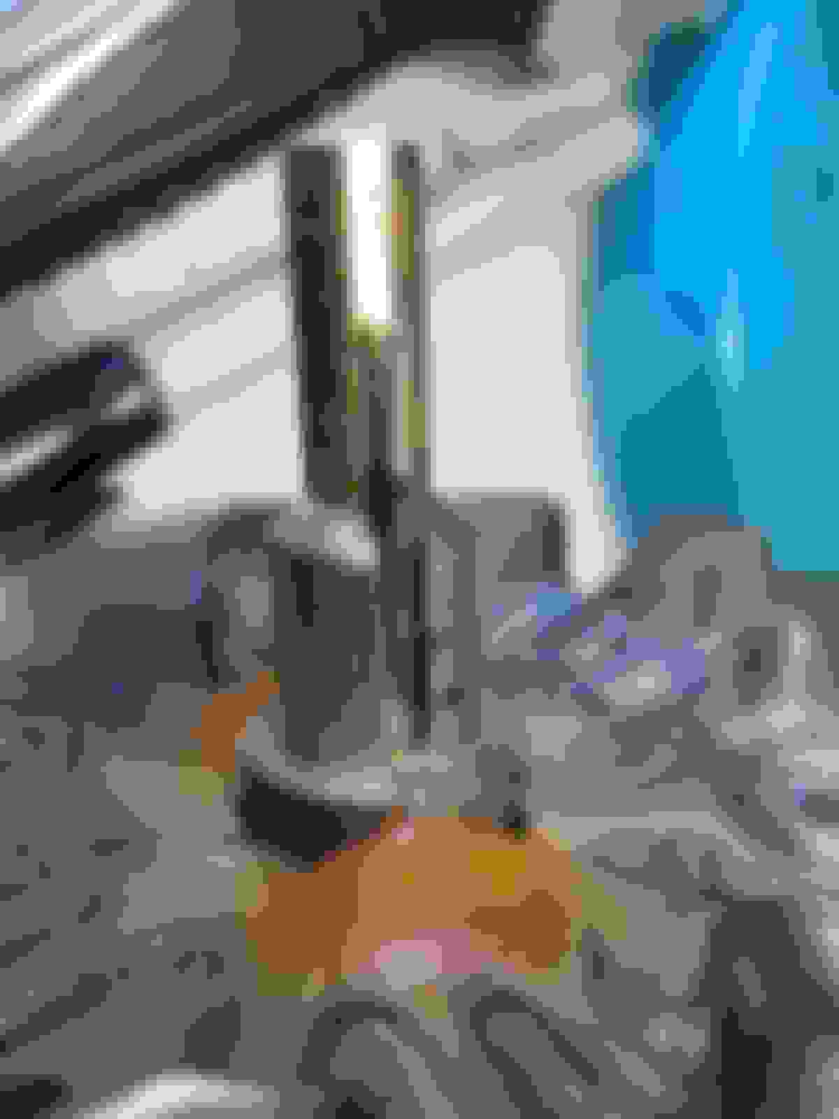
The existing wire, cleaned up, prior to cutting to length.
Same wire, cut and insulation removed that will fit in the splice.
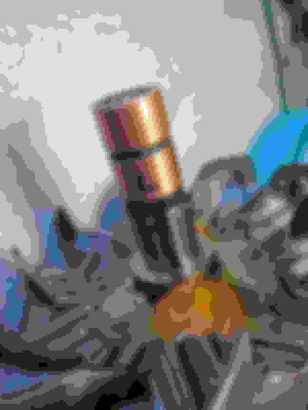
splice tube fit over existing wire.
Custom sculpted red insulator installed, tube seated, same thing done on the opposite side as well. New slip rings prepared - had to trim off some excess plastic, and cut and stripped the wires to exact length. New slip rings starting to press on. Perfect tight fit.
After pressing them down. I used a deep well 15mm socket, with some masking tape around the slip rings to prevent marring them. Tapped them down until seated. Then used a little screwdriver as a crimping tool to crimp the butt-splice tubes. Checked resistance to confirm the proper ~4 Ohm resistance between slip rings and infinity between each slip ring and ground. Some epoxy (JB Kwik Weld) to seal things up.
With the bearing washer (underneath, not visible), the bearing, and bearing retainer reinstalled over the slip rings and rotor shaft. From here on it's like a regular rebuild, and that video I linked earlier probably shows how to do it well enough. Pretty trivial to finish it up.
Thanks for the nice comments. Looking back a day later, I'll say the toughest part was the decision making in whether to try to do it the way I did, especially since I could not find any success stories out there for any method at all.
But that aside, once I chose the correct path, it actually was not too tough to do. And I expect more people should be able to do it, now that we know that the part shown in post #1 can be easily modified to work. BTW that stock photo in post #1 is not exactly what arrived - what I got is shown in my photos.
And as Yodaone suggested, now that it can be seen to be not difficult, Denso could at least consider making slip rings replacement part of their standard rebuild.
Once I was actually doing the job yesterday, the toughest part was custom sculpting those insulating shields. And I did that to get it done with the parts I already had. If doing it again, or if anyone wants to do it this way, I highly recommend getting the correct splice tube.
The one I used (I looked it up and confirmed) is a 26-22 AWG noninsulated tin butt splice (seen in my pics above). The better choice, if I had to do it again, would be to buy an insulated version, like this one: https://www.ebay.com/itm/VELVAC-Butt...0/253053073813
Basically the same as the one I used, but with the hard plastic insulation already fitting well around it. You'd need to trim off the overhanging plastic from the ends.
Obvious, yes, but I was just charging ahead with the parts I had on hand at the time, willing to put in a little effort vs. waiting and buying the right parts.
EDIT - I looked at that page again, and noticed that particular item has a ridiculously low temperature rating of 90*F. Maybe it's made from butter, or maybe it's underrated. But it would be better to choose something that looks like that, with a higher temp rating.
For the noninsulated ones I used, they had an outer diameter of 2.0 mm. And the width of the rectangular channel in the rotor shaft was about 3.0 mm, so the insulation can be up to 0.5 mm thick. This insulated butt splice would probably need a little trimming to fit that, but it would be preferable to the extensive trimming I did when starting with something different.
The bare wire on the field windings side is probably 20 or 22 AWG, since it is a very snug fit inside the tube. The wire from the new slip rings is probably closer to 26 AWG, so it slips in easily. That's why when doing it, I tapped the tube onto the thicker wires first, then the slip ring wires could easily slide in while tapping the slip rings down on the shaft.
Wow, if there were Oscars for DIY, this would be it. "May I have the envelope please..."
Oldskewel, where did you find the new slip ring if you don't mind my asking?
Wow, if there were Oscars for DIY, this would be it. "May I have the envelope please..."
Oldskewel, where did you find the new slip ring if you don't mind my asking?
slip rings came from eBay seller maniacelectricmotors
item title is "Alternator Rotor Slip Ring for Denso Alternators"
This post is to add to the good information contained in this thread. There isnt alot on the web about it replacing sliprings. Before I begin this rather long post I would like to say a few things.
There is no need to bang, beat, or force the parts in these alternators. It may seem at first some things are 'press fit', and while I use that term, they dont, at least in my unit, meet the technical definition of 'press fit'. They are simply stuck on with dirt and grime. The point is useful in the applied force required to remove things like the housing, or bearings. I dont like to criticize, but the man in the video posted might be a professional, but is not acting like one... Those are 'days of the old' techniques, and they dont work so well on modern components. You have been warned.
Your alternator might be different. Expect it to be. Also, I would not recommend this for a 'first time' rebuilding an alternator, nor if you need your vehicle working quickly, or cannot afford to replace your alternator...
4. remove the screw retaining the Brush holder assembly, and the terminal block assembly, and remove them.
5. Remove the diode assembly
6. (if needed) GENTLY tap the housing with plastic, rubber or wood NOT DEADBLOW hammer until slight 'hollow' sound indicating housing has seperated.
7. rotor shaft though rear bearing is holding rear housing on. It must be pressed off. There are many ways to remove, but improperly done can result in damage. Please borrow a puller from auto store if you dont own one.
8. Remove rear cover
9. remove front pulley retaining nut - Right hand thread (regular thread)
10. Remove pulley and thrust washer. My pulley wiggled off by hand, you may need to use a puller on yours.
11. Gently tap rotor shaft with soft rubber mallet to dislodge rotor from front housing. You may be able to work it off by hand.
12. Using a three jaw puller (not pictured) or a bearing separator, carefully remove the bearing from the shaft. NOTE: I could not locate my puller, and used two (2) #1 slotted drivers. Please DO NOT pry against the fins! That is actually a fan, and it is balanced at the factory. Look at the 5 o'clock position of the fan in the picture. Notice the drill hole. That is where it was balanced. There should be room to slip the pry device between the fins if you use this method. The bearing is NOT Pressed on, or super tight, and should move at around 15-20 lbs pressure. Rotate, and or lube the shaft to help the bearing slip off easily.
13. Using a heat gun on high and an old screw driver, begin to carefully work the epoxy loose on both side to reveal the wire junctions. It is important to note that 'digging is not needed at this point. Your objective is to 'reveal the wire junction so they can be disconnected without damage. Its also worth mentioning that the epoxy does not liquefy, it just gets soft. Apply heat as needed to keep it workable.
14. Using the heat gun to keep the epoxy soft, and an angle pick, or similar, carefully excavate as much epoxy around the wire junctions on both sides. on my unit the area turned out to be a hole approx 10mm round x 10mm deep.
15. When enough material has been cleared, gently pry up on the wire junction with heat applied. One came loose with the heat gun, the other I used a quick blast from the torch. Note that the wire from the slipring had been folded over, and slightly crimped onto the winding wire. The angled pick offered some help here to gently pry up with the heat applied.
16. Note the depth of the slipring on the shaft.
17. On my unit there was epoxy between the slipring and the shaft. Using a propane torch, and pliers heat the slipring QUICKLY and evenly (some skill is required here). Then grip gently (it is copper) and twist. If it doesn't twist/grip a little tighter, or apply more heat.
The slipring wires are potted in epoxy down the side of the shaft. Dont worry about them now, just rip the rings off the wires they are no longer connected to your rotor windings. They will be removed in the next step
A note For the inexperienced. To heat the sliprings quickly, set your torch on high, and hold the flame with the darkest blue torch flame very close (maybe 1/2 inch) for a few seconds then quickly move it to the opposite side. Few seconds on one side, then move to the other. Total time around 10-12 seconds. Scraped up bits of epoxy may ignite, so don't be alarmed.
18. Again, heating with a torch, and using needle nose pliers, remove the wires in the two channels that run down opposite sides of the shaft.
19. Clear away any remaining epoxy from the shaft, fan assembly, and wire junction holes. take care not to damage the winding wire that should be protruding from each hole.
20. Using a BRASS (NOT STEEL) <---IMPORTANT wire brush, remove any remaing debris from the rotor shaft, and grooves. PLEASE DO NOT SAND THE ROTOR SHAFT!!
21. To clean up around the wire junction holes (I'm pointing to with the pick), I used some medium grit sandpaper
22. using a suitable ZERO RESIDUE cleaner, clean the shaft, grooves, and areas around the wire junction holes.
23. Please follow the underline in the pic to see the highlights.
a. Cold weld formula
b. Sets in 4-6 hours
c. Fully cure in 24 hours
d. high temp formula is required
24. I used a scale to mix the epoxy evenly for maximum strength.
25. Apply the epoxy to the shaft and the grooves where the wires run on the side of the shaft. My replacement slipring was very tight, and I believe inteneded to be retained by friction; however I added the epoxy anyway
26. press the slipring onto the rotor shaft using a bearing installer, or vise. Please DO NOT hammer this on. It is copper and will deform even with a plastic or rubber mallet.
27. Check your depth fitting of the slipring on the shaft.
28. Push the wire into the shaft channels, and make sure the wire is embedded in epoxy. Then fill the shaft channel with expoxy until it is full
29. Measure and cut any unneeded wire. Start a little long then trim as needed.
For the inexperienced: If you cut too short and you cant make the connection. Too long and it could potentially ground out on the area around the junction.
30. Use an xacto, or razor blade to strip the insulation.
31. If desired, crimp one wire around the other to form a 'mechanical' connection.
32. solder the junctions. hot, rosen core, no acid.
33. run a continuity test on the windings, and make sure you have good connection, and nothing grounded out.
34. Pot the wire junctions with epoxy, and fill the wire channels smooth on the shaft. Dont be stingy, but no big globs either.
35. Using a pick or similar make sure the epoxy encapsulates the wires on all sides, and do your best to leave an even amount of epoxy on each side (balancing)
36. Clean the shaft the best you can, again I used brake kleen, but any zero residue will work, and wipe off any errant epoxy, and especially wipe the the slipring journal with zero residue cleaner to prevent the possibility of an 'epoxy film' (you can see in the pic I'm not done!)
37. Please allow the unit to rest for a full 24 hours before service; however final assembly acceptable after 15 hours.
38. install the rear bearing thrust washer, and the rear bearing. I like to use a tiny bit of 'assembly lube (Vaseline) to keep bearings from binding while pressing.
39. Remove the screws holding the front bearing cover
40. Remove the front bearing with bearing installer or similar tool
41. If you carefully clean the housing (no wire brush!) where the bearings seat, the bearings should slip into the housing easily (rear housing shown in first three pics, front housing in fourth pic)
The front bearing should almost drop in...
42. Install the rear bearing by hand, a bearing installer, vise or press. PLEASE NO HAMMER. An alternate way may be to install the bearing in the rear housing, and press the housing on. I did not try this.
43. Reinstall the rear housing, and torque the bolts to 9 ft lbs (108 in lbs)
44. Reinstall the diode, insulator bushings, and the 4 retaining screws (please note that the final torque on the screws is with a HAND DRIVER, not my impact!)
45. Replace the front dust cover (don't forget it like I did!), and install the terminal block, brush holder, and rear dust cover
46. Replace the rear housing dust cover and torque the nuts to 7 ft lbs (84 in lbs). Reinstall install the ground strap
47. Replace the insulator bushing, and nut and torque to 10 ft lbs (120 in lbs)
48. Install the pulley thrust washer, pulley, flat washer, and nut
49. PLEASE DONT PUT THE PULLEY IN A VISE! You are supposed to restrain the pulley with a strap tool (I think) I tried a makeshift one with some old tow straps that didnt work. In the end I used an impact WITH A MEASURED TORQUE SETTING OF 25 FT LBS.
50. Finished
IMPORTANT NOTE: I did not record the orientation of the slipring journals to the wires (which side went to which). I got lucky, in my case it didnt matter as the field wires on my truck are interchangeable (supposedly). Once the wires are exposed, before de-soldiering, please label or mark the fan plate with top and bottom orientation of the slipring journals.
Helpful things:
Go to the parts store and rent all the specialty tools you need. Its worth it.
Take pictures, or better video. Super helpful to remember where things go.
Bag your parts, this is an overnight job, and the gremlins may steal parts from your work bench!
Things to avoid:
Getting in a hurry. If this is your only ride, make sure you dont need to go anywhere for a day or so.
Prying the case open
Over torquing screws/nuts
Deadblows (metal hammers) Please leave them in the toolbox, you DONT NEED THEM FOR THIS JOB.
Forcing anything. Nothing in this unit is that tight.
clamping in your vise tightly

 06-30-19, 06:34 PM


 I'll just buy a new one.
  It even took me too long to read all that.
 ")