When you click on links to various merchants on this site and make a purchase, this can result in this site earning a commission. Affiliate programs and affiliations include, but are not limited to, the eBay Partner Network.
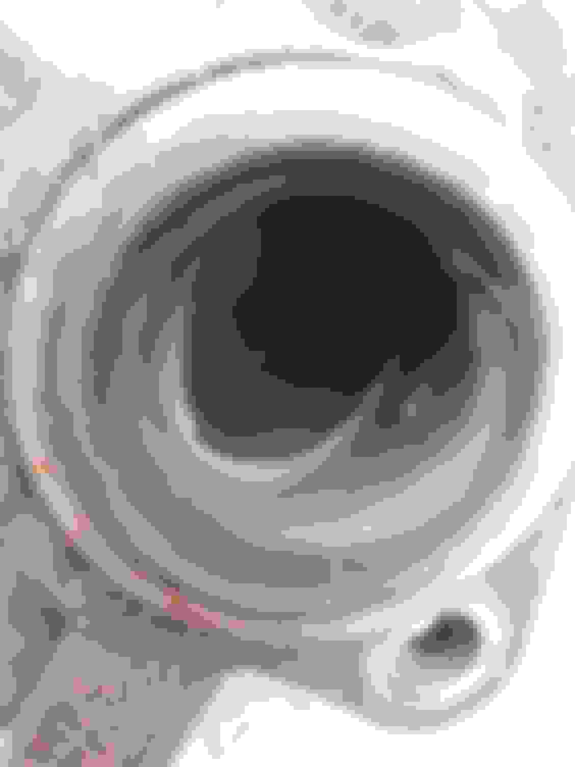
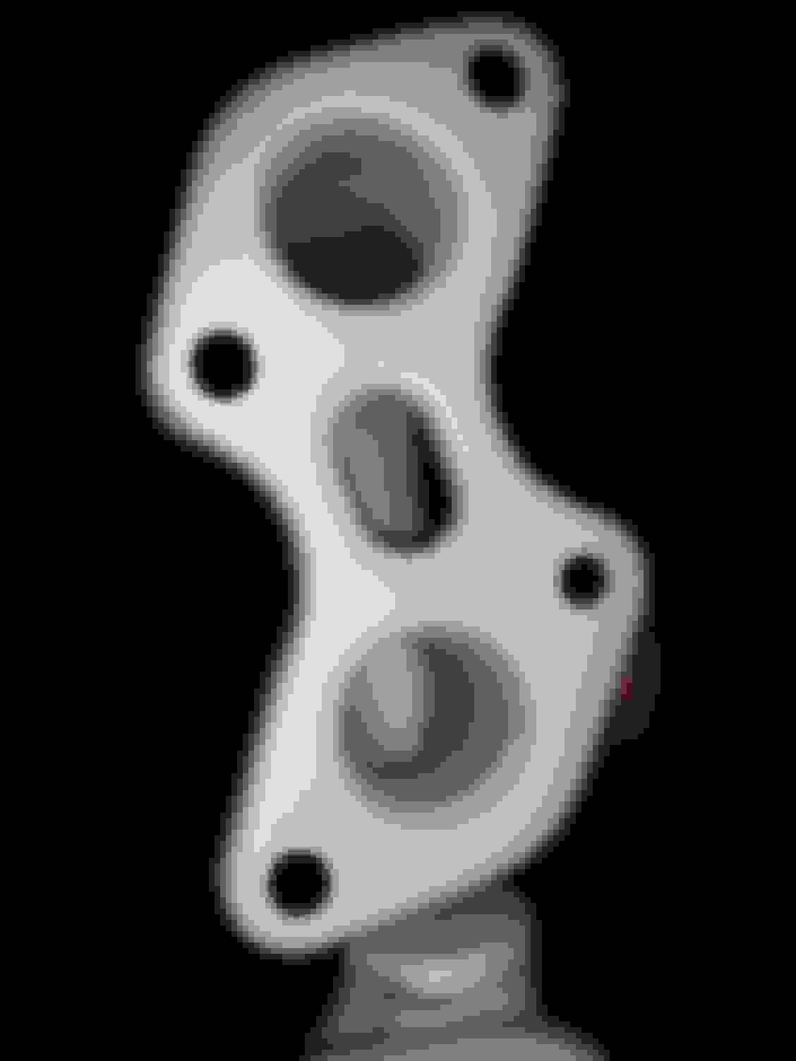
After separating the exhaust manifolds from the heads, looked down flange side ports on right bank exhaust manifold.
Room for improvement..
Right bank exhaust manifold rear ports. View looking down rear port right flange side..the OEM did a poor job transitioning to the tube below.(welded perpendicular to pipe) The exhaust flow snags and creates turbulence. Grinding the lower tube out of the flow path should offer improvement.
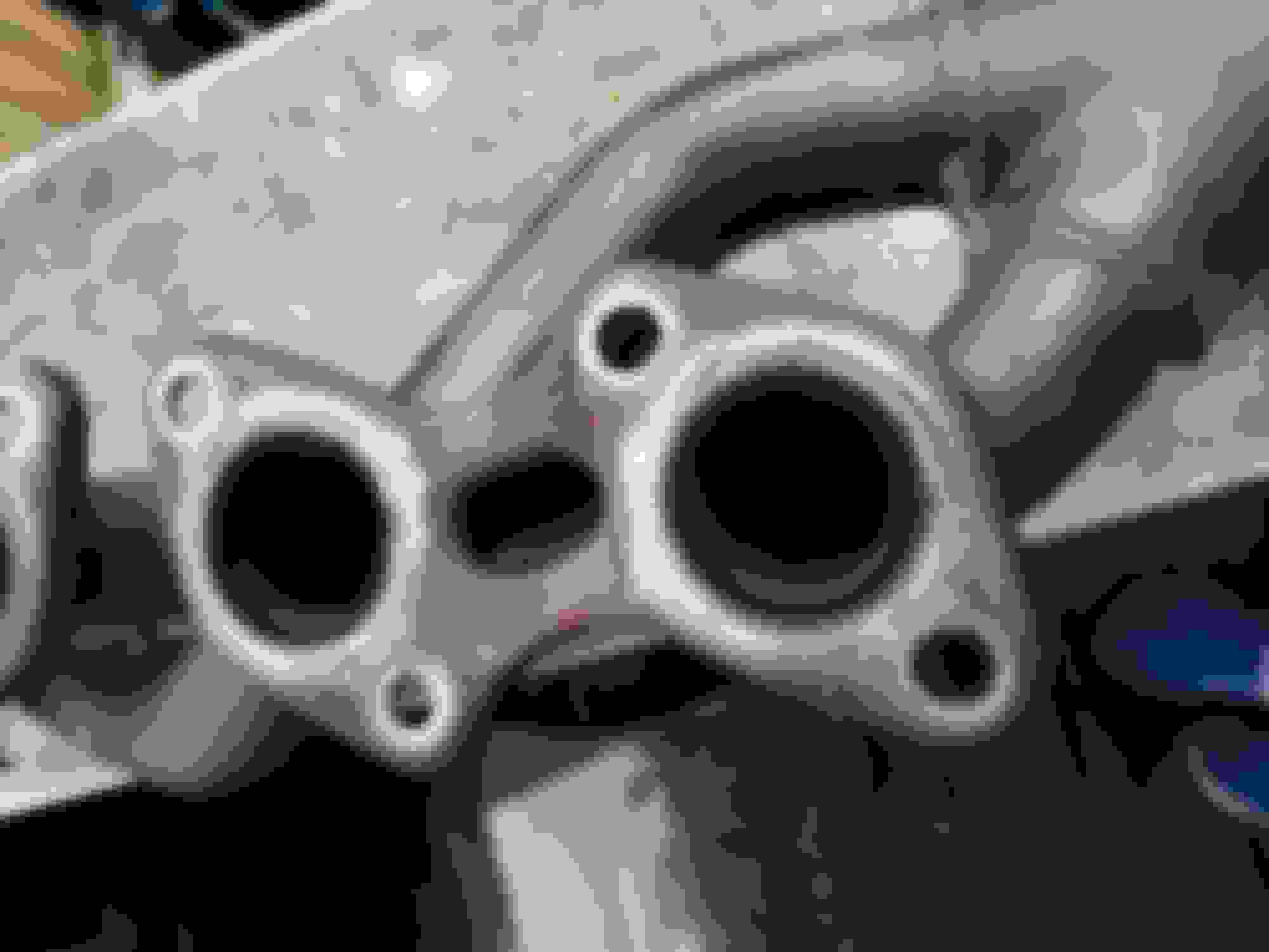
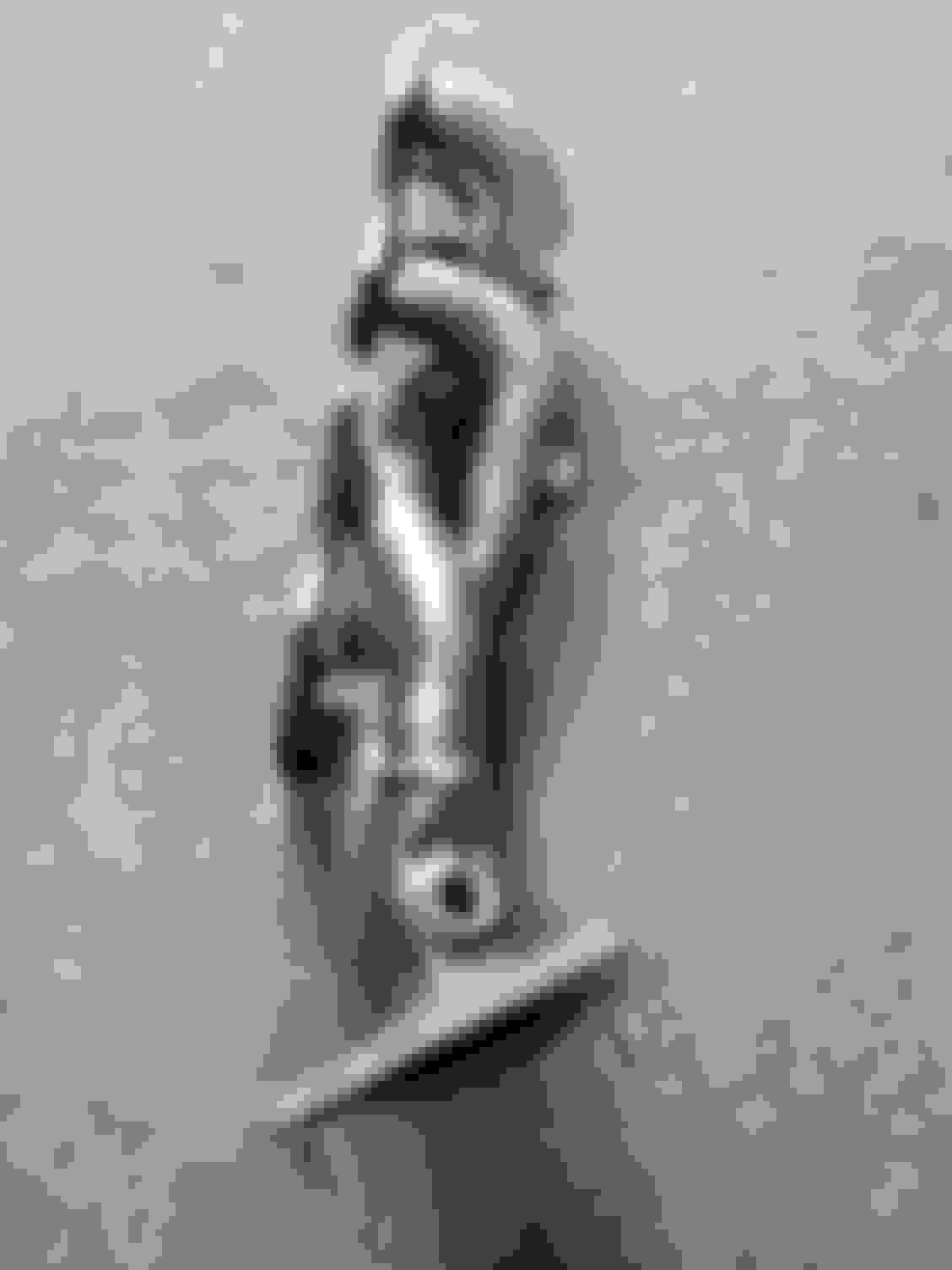
Left bank exhaust manifold..rear ports have similar blockage as right side. Left side exhaust manifold is in very good condition for 20 years old. A slight sandblasting of flanges and tubes will have it like new. Notice the rear flange tubes are perpendicular to collector tubes. Side view of area depicted above.
I thought that the first thing you do with exhaust manifolds if you care about engine performance is to make each pipe the same length. "Equal length headers," for example. The basic concept is that each exhaust pulse (from each cylinder) needs to travel down its pipe, and not crash into another one when they merge. Having all pipes equal length means the pulses are arranged in sequence without collisions when they merge.
And if you don't do that, there's not much point. Which may be fine because the exhaust is not the limiting factor.
But that's just general understanding. Is there a reason it's different for these engines?
Great workmanship... However, additional tubes are used, so more flow capability but it is authors opinion this affects scavenging, exhaust velocity, and low end torque. The OEM configuration pairs two exhaust ports to two collector tubes.
Contacted PPE who advised 20 - 25 rear wheel horsepower increase.
This figure is higher RPM dyno figure.
An excerpt from the vivid racing link:
"PPE Headers have a significant increase in flow compared to the stock manifolds. Tube lengths and diameters are increased coming together into a ported 4-1 or 3-1 parallel merge collector. Completely TIG welded construction with thick 16 gauge tubing for long lasting power gains."
Focusing on;
"Have a significant increase in flow" and "Diameters are increased".
As with porting cylinder heads, increased flow does not always equate to increased velocity...and velocity and exhaust scavenging is important for low RPM torque.
Here not only increased diameter tubes, but increased number of tubes does not suggest increased low end power.
It is my opinion that using the base OEM configuration as a template, improving or eliminating sharp transitions to reduce turbulence.
The OEM exhaust manifolds with simple modifications can offer increased flow, without affecting drivability, by removing obstructions depicted above.
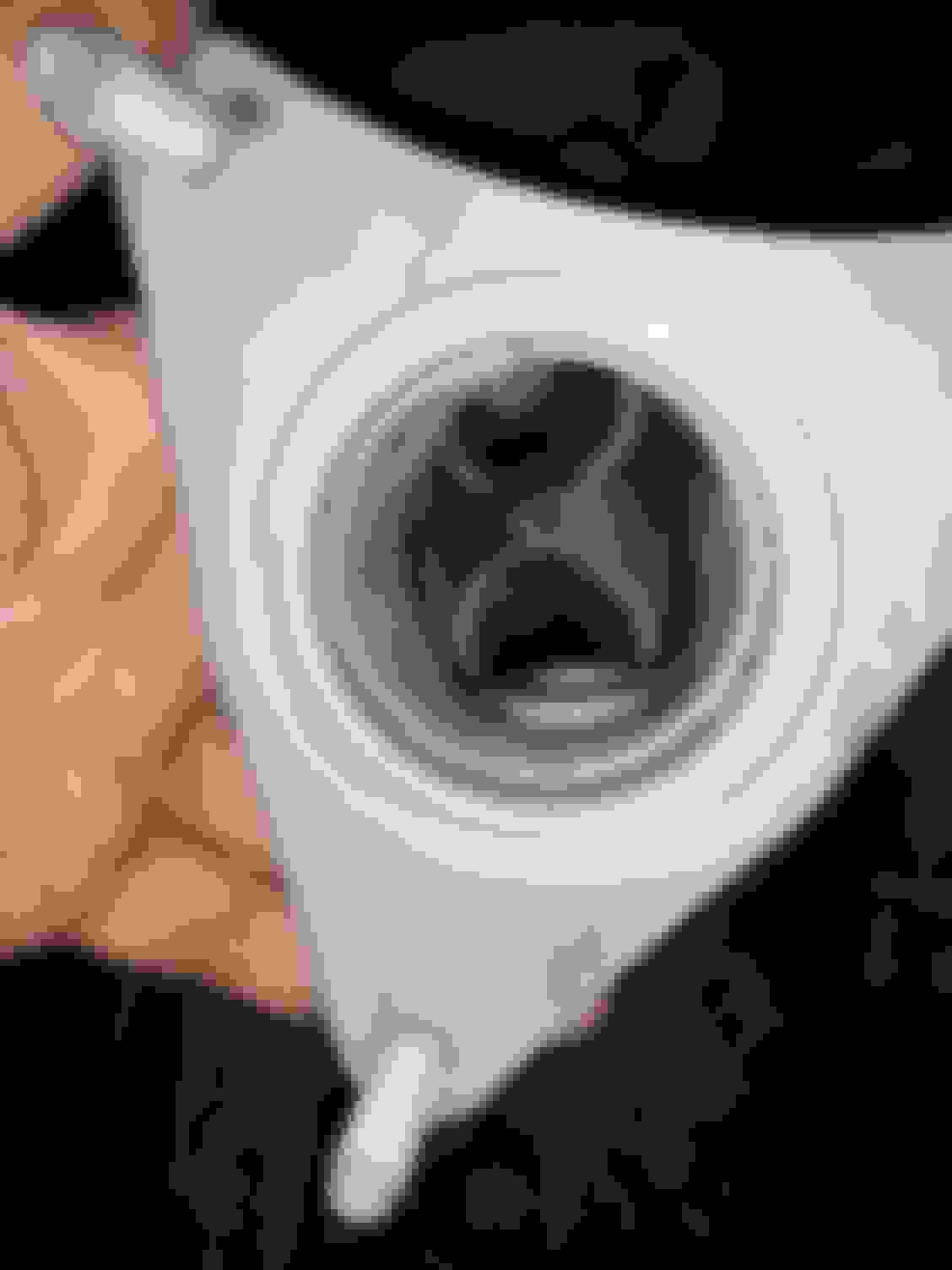
The third ports on the right exhaust manifold also suffers from turbulence induced by the T junction capped tube scheme.
Cutting off the log end, forming and welding in a more transitional piece of tubing should reduce turbulence. My manifolds are being cleaned, so located image of this right exhaust manifold online depicting third port with log end cap on tube. Possibly something could be fabricated to improve on this.
Could approach a shop about a Tri-Y custom build. Are you also intending to replace the rest of the exhaust system?
Am not replacing the stock exhaust system but am planning a few modifications.
LS430 has a better exhaust layout (from exhaust manifolds back) Perhaps components could be configured for the LS400.
Next project will be to eliminate the sharp transition and oxygen sensor blockage on Y-pipe.
The post catalytic converter oxygen sensor probe is a significant blockage in exhaust stream. This sensor serves only to monitor when catalyst levels fall below certain efficiency. Spark plug anti-fouling spacers could solve this.
You'll not like the pinch joint at the Y separation. There are a couple threads about the exhaust section where Jbrady breaks it section by section to improve flow. The muffler delete being one of the simpler ones to improve flow. PureDrifter and SKperformance I want to recall had threads on their exhaust builds. (That's tough to recall 16 years worth of threads.)
Picked up exhaust manifolds from Ace Sandblasting in Chicago.
They did an excellent job.
Exhaust manifolds after sandblasting... Next will remove this shrouding from exhaust ports The oxygen sensor bung impedes exhaust flow. The only turbulence should be from the sensor probe.
Honestly very interesting. I applaud you for going this far! Damn. With how reliable these engines are I can�t find many people that have removed the heads! Hahaha.
To me the PPE headers would be the only way to go at this point. At the very least you could call them out on the BS of that much RWHP gain (or not?!). These cars aren�t meant to be driven as high RPM cars but damn, 30 hp gain is nothing to scoff at. Over 10% gain... impressive if true.
we�ve spent over $2k on my motorcycle to get it to 200 mph but still no dice, and it goes 185 mph stock. Point being, a bolt on like this, if true, would change the dynamics of performance talk for the 1 & 3 UZ forever.
You'll not like the pinch joint at the Y separation. There are a couple threads about the exhaust section where Jbrady breaks it section by section to improve flow. The muffler delete being one of the simpler ones to improve flow. PureDrifter and SKperformance I want to recall had threads on their exhaust builds. (That's tough to recall 16 years worth of threads.)
Located a Midas shop in Chicago with background in porting to remove the shrouding in the exhaust manifold runners.
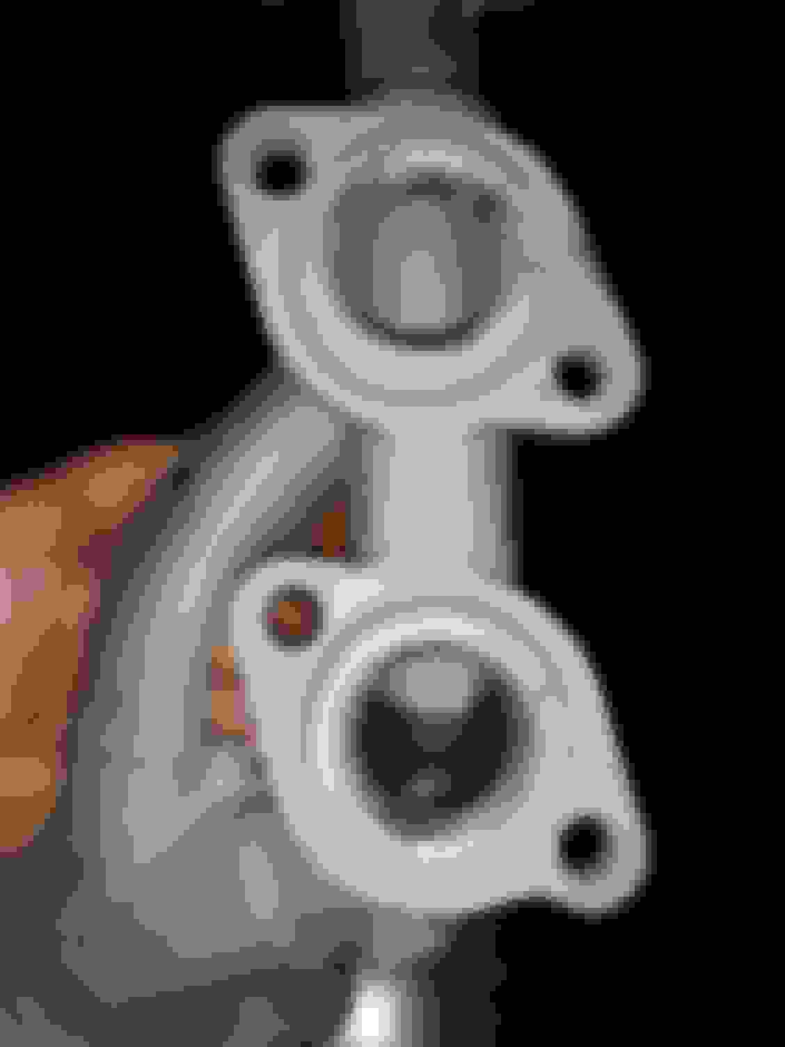
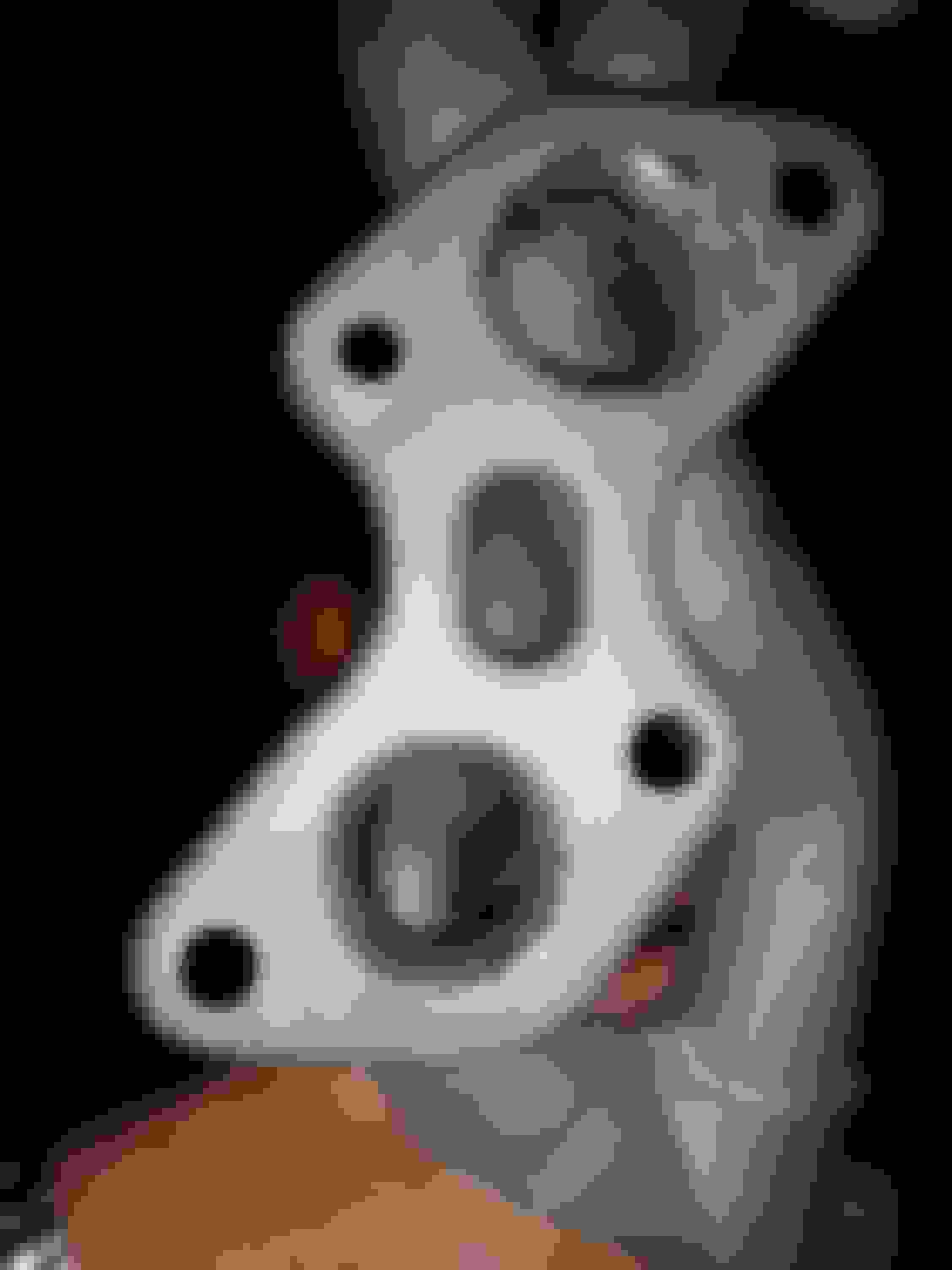
Following are images of left and right bank exhaust manifolds from 1999 LS400 depicting removal of obstruction from the two rearmost ports of each manifold.
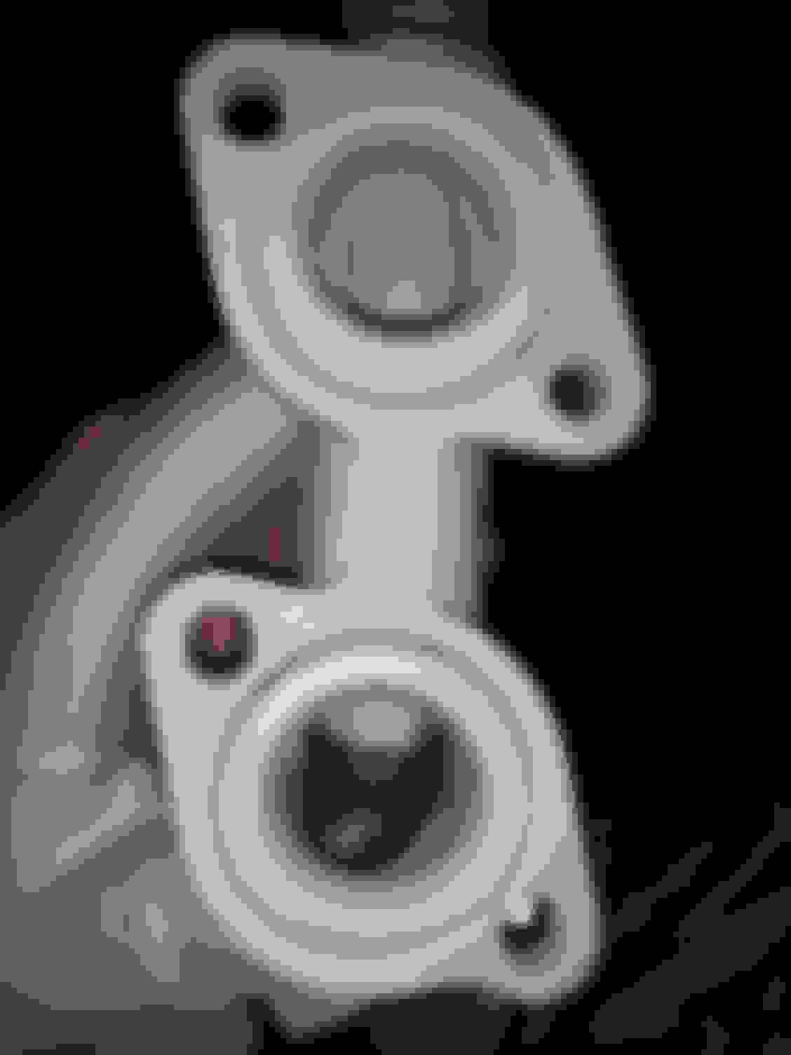
Rear ports of right exhaust manifold after removal of shrouding Rear ports on left exhaust manifold after removal of shrouding.
Located a Midas shop in Chicago with background in porting to remove the shrouding in the exhaust manifold runners.
Following are images of left and right bank exhaust manifolds from 1999 LS400 depicting removal of obstruction from the two rearmost ports of each manifold.
Rear ports of right exhaust manifold after removal of shrouding Rear ports on left exhaust manifold after removal of shrouding.
Am seeking thermal readings from Exhaust Manifolds, Exhaust Manifold Shields, Catalytic converter shields, and post catalytic converter flange on 1998 -2000 after highway driving.
I thought that the first thing you do with exhaust manifolds if you care about engine performance is to make each pipe the same length. "Equal length headers," for example.Is there a reason it's different for these engines?
The 1UZFE engine has a unique firing order that changes the nice exhaust flow symmetry you may be envisioning. Look at how it fires completely across the engine at 1-8 then fires another cylinder on the same bank at 4!
Colin
Based on the sequence, whatever it is, I believe the first step in trying to optimize exhaust flow is to make the pipes the right lengths to avoid collisions - i.e., two exhaust pulses trying to squeeze into the same spot at the same time.
If the firing cylinders would alternate between banks (they do not on this engine, e.g., 5-7 and 8-4), then equal length pipes does this pretty simply, avoiding collisions at all RPM.
Based on what the exhaust manifolds look like, does it seem like they tried to do this? I have not looked carefully at all. Just interested.

 10-03-19 | 06:29 PM