When you click on links to various merchants on this site and make a purchase, this can result in this site earning a commission. Affiliate programs and affiliations include, but are not limited to, the eBay Partner Network.
Front and rear Rubber Guibos and center bearing support on 1999 LS400 are tired.
The Guibos (flexible rubber driveshaft couplers) have age-hardened and are showing signs of cracking.
The center bearing is droning and its rubber support is age hardened.
Until recently, the entire driveshaft assembly with guibos was available for $850 - $900.
Separately, dealer guibos are $275 each, center bearing $175.
The U-joint is not serviceable, but was able to locate a driveshaft repair facility that could replace U-joint for $175.
However, Lexus parts department informed me that a new rear half section driveshaft assembly was available for ~ $400.
It includes assembled: rear guibo; center support bearing, rear shaft section with U-joint and splined shaft (splines slip into front half of driveshaft section).
So one new guibo, center bearing and U-joint would cost $625 when reusing old shaft.
In view of pricing, purchasing a new rear shaft assembly seemed logical.
The front section and its female splines appear in good shape.
However, the new rear driveshaft section does not contain balancing tabs.
So I inquired and Toyota advises the rear shaft I purchased is balanced...without any balancing tabs...hmm
On information, two piece driveshafts are balanced as an assembly, here with the guibos attached.
So I inquired how the shaft was balanced without the front section (discontinued)
Also inquired how a driveshaft balancing machine be fixtures to accommodate a Lexus style driveshaft and whether Toyota North America has a driveshaft balancing machine.
Balancing both shafts together with (flexible) rubber guibos and a center bearing with rubber isolator flexure seems counterintuitive.
Fixturing the entire driveshaft (with guibos) in a balancing machine, (and properly aligning shafts at center bearing) would require using transmission and differential flanges in the chucks....(happily I have extras of both)
Has anyone noticed balancing tabs on the front and/or rear section of their original driveshaft or have experience balancing this type of driveshaft (Single shaft with front and rear u-joints doesn't count)
As am using a new rear section, seeking input on phasing.
Thanks.
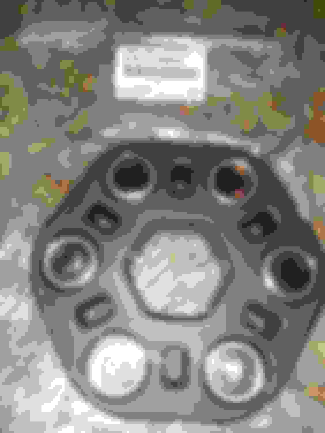
Rear driveshaft section is 37110 in Lexus parts diagram. Toyota/Lexus P.N. 37110-30050 P.N. 37110-50050 is rear driveshaft section depicted. Acquired second (front) rubber guibo separately P.N. 37511-30020.
The new guibos are more pliable than the old ones, so this should improve transmission shift isolation and drivetrain harmonics.
You can simply have each part balanced individually to be neutral. It will cost more and take longer but then each part will not rely on the rest to be in balance. Same thing when having engine work done, just have everything that spins balanced.
You don't need to do the whole thing as a unit just like you don't need to have an engine fully assembled to balance it nor do you need the transmission converter and flex-plate attached to get everything dialed in. You can do each part by itself.
Just like the simpler one piece type driveshafts, you take them totally apart and then eat both yokes and the actual shaft perfect then put them back together.
As am using a new rear section, seeking input on phasing.
I hope you can successfully pull this off. Yes, you WILL need to balance entire assembly. Even with individual sections well-balanced, there are dynamic forces that arise when you join them. Each individually balanced assembly will have specitic and unique "periods" of imbalance both in the radial and axial directions as the rpm changes. Factory shafts generally have two small weights per end of each shaft.
The guibo flanges are supposed to be splined such that they are perfectly aligned at each 120* bolt hole. You will want to phase mark them in case you need to rotate the shafts in relation to each other.
Weigh your bolts (or look for factory stamped numbers adjacent to the "11"s on the bolt heads. The factory did their finish-balancing by using different weight bolts (I think the range was 5-10g). The weighted bolts are between the guibo and the driveshaft flanges (that is why you are not supposed to ever remove them on the factory build shafts)
You will have an opportunity to finish balance by trial and error, but what a PIA.
I used hose clamps. I put the car on jack stands at the camber control arms (fully sprung proper ride height) removed wheels, lowered exhaust, removed heat shield, used a board between the accelerator and the front seat and powered the seat forward to run the driveshaft at 30/60/90 mph. Make sure ebrake adjustment and rear calipers are retracted!)
Every bit of weight added to a driveshaft changes not only the radial inertia, but has a profound effect on the other shaft! Weight does make the shaft want to "tip" front-to-rear, which causes dynamic effects through the u-joint.
I ended up parsing down the weights to one clamp on rear shaft, it is smooth at 30, there is a period at 55 and 90 mph, but it is almost unnoticeable from the driver's seat. Read up on shaft dynamics. It is a horrible science. It took me 62 miles on the odometer up on the jack stands.
Colin
You must have half shafts at normal ride height.
I got rid of the larger clamp which used to allow me to do a verier weight adjustment (180* was an effective "0" weight, 90* was 1/2 weight). Even though I had a perfect 30 and 60 mph, that additional clamp screwed everything up above 80 mph. Without, I still have a good 30, but not so good 55-60.
You can simply have each part balanced individually to be neutral. It will cost more and take longer but then each part will not rely on the rest to be in balance. Same thing when having engine work done, just have everything that spins balanced.
You don't need to do the whole thing as a unit just like you don't need to have an engine fully assembled to balance it nor do you need the transmission converter and flex-plate attached to get everything dialed in. You can do each part by itself.
Just like the simpler one piece type driveshafts, you take them totally apart and then eat both yokes and the actual shaft perfect then put them back together.
Located this answer contained in a forum post I initiated:
"Unbeknownst to most driveshaft shops, Lexus does final balancing with different weight guibo bolts between the driveshaft flange and guibo disk. That is why they plead that you only detach driveshaft from car using the guibo-to-transmission flange or guibo-to-differential flange. Weigh your friggen bolts anyway if the drive shaft has ever been removed or your guibo disks ever replaced."
If different weight driveshaft bolts accomplish balancing, then ihis would explain absence of balancing weights.
This does not explain how the center section of driveshaft furthest from guibos is balanced.
Toyota doesn't clarify, while Lexus parts diagram/ P.N. list contains a full range of driveshaft weights...which raises the question.
Will phase the original front driveshaft section to the new rear section and run at speed to determine whether imbalance.
Right now, running on a private road, imbalance can be felt from mid-center starting at about 90 MPH and uncomfortably preaent at 100 MPH.
Prefer to perform repairs equal or better than OEM specification, but this one has been a real.head scratcher.
Was investigating a composite driveshaft, however the vendor quoted $3,000 for a one-piece driveshaft which would have eliminated center bearing and reduced the shaft critical speed to 100 MPH (from 149 limited speed) but did not accommodate the need to telescope the shaft (at splined section) to clear the transmission and differential centering pins.
Further, the goal was to eliminate the need for rubber guibos in anticipation that the composite shaft would offer the same isolation and NVH reduction...
I hope you can successfully pull this off. Yes, you WILL need to balance entire assembly. Even with individual sections well-balanced, there are dynamic forces that arise when you join them. Each individually balanced assembly will have specitic and unique "periods" of imbalance both in the radial and axial directions as the rpm changes. Factory shafts generally have two small weights per end of each shaft.
The guibo flanges are supposed to be splined such that they are perfectly aligned at each 120* bolt hole. You will want to phase mark them in case you need to rotate the shafts in relation to each other.
Weigh your bolts (or look for factory stamped numbers adjacent to the "11"s on the bolt heads. The factory did their finish-balancing by using different weight bolts (I think the range was 5-10g). The weighted bolts are between the guibo and the driveshaft flanges (that is why you are not supposed to ever remove them on the factory build shafts)
You will have an opportunity to finish balance by trial and error, but what a PIA.
I used hose clamps. I put the car on jack stands at the camber control arms (fully sprung proper ride height) removed wheels, lowered exhaust, removed heat shield, used a board between the accelerator and the front seat and powered the seat forward to run the driveshaft at 30/60/90 mph. Make sure ebrake adjustment and rear calipers are retracted!)
Every bit of weight added to a driveshaft changes not only the radial inertia, but has a profound effect on the other shaft! Weight does make the shaft want to "tip" front-to-rear, which causes dynamic effects through the u-joint.
I ended up parsing down the weights to one clamp on rear shaft, it is smooth at 30, there is a period at 55 and 90 mph, but it is almost unnoticeable from the driver's seat. Read up on shaft dynamics. It is a horrible science. It took me 62 miles on the odometer up on the jack stands.
Colin
You must have half shafts at normal ride height.
I got rid of the larger clamp which used to allow me to do a verier weight adjustment (180* was an effective "0" weight, 90* was 1/2 weight). Even though I had a perfect 30 and 60 mph, that additional clamp screwed everything up above 80 mph. Without, I still have a good 30, but not so good 55-60.
If Driveshaft shop has splined male and female fixturing and, driveshaft yokes plates, for balancing machine chucks, would proceed in this order:
1.) Individually balance front and rear driveshaft sections without rubber guibos.
2.) The rear section could be balanced first without the front splined section by fixturing shaft U-joint to a U-joint flanged fixture on balancing chuck.
3.) Rear section would then be rebalanced with splined section in place....if minor imbalance, as practical weight could be removed from the yoke area on splined section
4.) Install rubber guibo(s) on individual shaft section(s) and balance with guibo to driveshaft using variable weight bolts. Actual transmission and differential flanges would also be used in this operation...thereby allowing balancing at 60 degree increments. (Not really ok with balancing the guibo/ shaft assembly at 120 degree increments)(!)
5.) Assemble (in phase) the driveshaft and rebalance with shafts in perfect alignment, up-down, side-to-side via the center
bearing positioned, shimmed and mounted using laser.
A well made driveshaft, but room for improvement on balancing.
A well made driveshaft, but room for improvement on balancing.
A very fine driveshaft, released to the wilds of dealer mechanics and now any ol' shade tree mechanic, none of whom follow the directions.
I just finished a 16-hour 800 mile round trip from Pensacola FL to Atlanta GA and back @ an average speed of 80 mph. Underway, it took time for me to tune into the imbalance periods. 50/72/93, and more noticeable over time as I acclimated to the ambient sounds and feeling. There is a wheel imbalance now coming through the steering wheel that takes the focus off the driveshaft. At exactly 87 mph, imbalance is imperceptible. I say good nuff for now.
Colin
If Driveshaft shop has splined male and female fixturing and, driveshaft yokes plates, for balancing machine chucks, would proceed in this order:
1.) Individually balance front and rear driveshaft sections without rubber guibos.
2.) The rear section could be balanced first without the front splined section by fixturing shaft U-joint to a U-joint flanged fixture on balancing chuck.
3.) Rear section would then be rebalanced with splined section in place....if minor imbalance, as practical weight could be removed from the yoke area on splined section
4.) Install rubber guibo(s) on individual shaft section(s) and balance with guibo to driveshaft using variable weight bolts. Actual transmission and differential flanges would also be used in this operation...thereby allowing balancing at 60 degree increments. (Not really ok with balancing the guibo/ shaft assembly at 120 degree increments)(!)
5.) Assemble (in phase) the driveshaft and rebalance with shafts in perfect alignment, up-down, side-to-side via the center
bearing positioned, shimmed and mounted using laser.
A well made driveshaft, but room for improvement on balancing.
You won't need to use the differing weight bolts if you have the guibos balanced, the process really isn't that complex but most don't need/bother to get it done professionally. A lot of drag racers who use the two piece setups hit over 170 mph on shafts that by the books should explode from critical speed issues don't have them explode since they have them setup to be neutral throughout the rpm band.
The shaft will have vibration occur along the length that is near impossible to fully cancel out at all rpm, but as said above you will chase it endlessly since it's very hard since the splined section allows very slight changes in length.
Your plan should eliminate nearly all the rotational imbalance. Mass dampers affixed onto the shaft halves may stop the lengthwise imbalance. Any play at all in the splines/joint will ruin the balance since the two parts will be able to move relative to each other and it will obviously result in vibration.
A very fine driveshaft, released to the wilds of dealer mechanics and now any ol' shade tree mechanic, none of whom follow the directions.
I just finished a 16-hour 800 mile round trip from Pensacola FL to Atlanta GA and back @ an average speed of 80 mph. Underway, it took time for me to tune into the imbalance periods. 50/72/93, and more noticeable over time as I acclimated to the ambient sounds and feeling. There is a wheel imbalance now coming through the steering wheel that takes the focus off the driveshaft. At exactly 87 mph, imbalance is imperceptible. I say good nuff for now.
Colin
It is misbalancing to balance two imbalanced parts together attempting to achieve balance...
What comes to mind are tires and rims.
(Have heard of balancing tires on the car spinning , tires, rims, brake rotors, hubs, halfshafts together...WHAT?)
Have yet to find a tire shop that first balances the rim, then the rim.and tire together.
Ideally, the tire is precision molded such that imbalance is non-existent... but we know that is not the case with all tire manufacturers.
Perhaps a forum member has information on how tire manufacturers determine acceptable imbalance range.
Before my next tire change will have my rims balanced (metal removed) with valve stem and then have a discussion with the tire vendor if excessive balancing weights are used.
Range varies based on expected use, look up how the McLaren F1 tire balancing is done as an example of extremely tight tolerance.
Also the entire point of the rubber disks are to give the torsional forces somewhere to dissipate into vs "hard" mounted yoke/flange setups
If the goal is higher operation speeds you MUST try to get the parts as balanced as possible so that there is as little uncontrolled forces as possible and to have the strongest possible parts so that any forces that will invariably occur will not cause as much deflection in the actual part. Same exact principle with engine balancing and material strength, these exact same principles are what snaps a crank if too much imbalance builds up for whatever reasons and why cranks have harmonic dampers.
It is misbalancing to balance two imbalanced parts together attempting to achieve balance...
What comes to mind are tires and rims.
(Have heard of balancing tires on the car spinning , tires, rims, brake rotors, hubs, halfshafts together...WHAT?)
Have yet to find a tire shop that first balances the rim, then the rim.and tire together.
Ideally, the tire is precision molded such that imbalance is non-existent... but we know that is not the case with all tire manufacturers.
Perhaps a forum member has information on how tire manufacturers determine acceptable imbalance range.
Before my next tire change will have my rims balanced (metal removed) with valve stem and then have a discussion with the tire vendor if excessive balancing weights are used.
So by this rationale a helocopter prop would be balanced with each blade individually, one at a time, then a final balance after all blades are in place?
Doubtful
So by this rationale a helocopter prop would be balanced with each blade individually, one at a time, then a final balance after all blades are in place?
Doubtful
No since they are all at the same point on the shaft, and I bet the weight spec is very tight relative to the blades overall weight. Your example would be akin to balancing a theoretical flywheel that had four+ equal parts and trying to get each 1/4 somehow balanced. Now getting each 1/4 as closely weighted and dimensionally accurate in terms of weight distribution and symmetry would be very helpful.
Dang, I just forked over $270 a piece for these! My car also still has a vibration I haven't figured out, even after replacing the whole driveshaft assembly with a good used one and new flex discs and center support. Now I am wondering if the shop that did it actually reinstalled those weighted bolts correctly...wow these cars are finicky.
Dang, I just forked over $270 a piece for these! My car also still has a vibration I haven't figured out, even after replacing the whole driveshaft assembly with a good used one and new flex discs and center support. Now I am wondering if the shop that did it actually reinstalled those weighted bolts correctly...wow these cars are finicky.
Ask your shop if they obtained AND read the Lexus shop manual before performing work...
Obtain a copy of the driveshaft section for your use.
Possibly they overlooked ..dropped of lost, or reinstalled only one side of the shim washers that go between the center bearing and chassis..Different thicknesses available to align the driveshaft.
Also, your differential may have worn bushings or require different thickness shim washers to properly align driveshaft...
As to the drivshaft side guibo bolts, it would appear they are used to balance the driveshaft through different weight bolts (or washers?)
Poor technique to balance a part at 120 degrees however.
Will use my transmission and differential yokes for fixturing driveshaft for balancing...but first will take both yokes and have them balanced before doing so.
Based on information I have so far, which is incomplete, it appears rebalancing is necessary when replacing guibos - even if maintaining same bolt orientation (!)
Still waiting for Toyota to respond as to proper technique and, or, whether they have balancing technicians and equipment stateside.. but will visit with driveshaft fabricator for his input.
Overall, he was very impressed with the quality of the Lexus driveshaft.
Toyota has not responded as to how they balance the driveshaft assembly or whether they have equipment stateside to do so.
Meanwhile, contacted Westport Machine Works in Sacramento, Califonia.
They manufacture a range of driveshaft manufacturing and balancing equipment.
Andy Vrilakas is familiar with the Toyota driveshafts yokes and provided several images of fixturing produced for the yoke end, but is investigating how the male and female splined ends would fixture.
My position is each section and component part should be balanced individually, before balanced together.

 08-22-20, 08:53 PM