When you click on links to various merchants on this site and make a purchase, this can result in this site earning a commission. Affiliate programs and affiliations include, but are not limited to, the eBay Partner Network.
Does the unused camera connector shape and terminal arrangement resemble either of these?
In addition to the red wire you used for ACC, what other wire colors are available at that connector?
There should be a similar connector and harness on the right side, intended for the right mirror camera, that could be used to pass 3 wires into the passenger door (ACC and 2 switch wires).
Yes, the connector looks like the M11 above, and yes, that is exactly what I had in mind, to pass the ACC and 2 switch wires through the right camera wiring.
NOTE: even though I gained automatic mirror folding with these modules, I actually lost the manual (intentional) folding... unless you have any idea on how to get that back with the current setup... Presently, after installing the automation modules, pressing the fold/unfold/auto button does absolutely nothing.
I wouldn't mind having another button somewhere else to fold my mirrors manually.
I think this is the current circuit arrangement:
Where did you connect the movable terminal of the switch ("?" in the drawing)? Try connecting it to ACC and see if the switch then has any effect.
I think this is the current circuit arrangement:
Where did you connect the movable terminal of the switch ("?" in the drawing)? Try connecting it to ACC and see if the switch then has any effect.
I didn't connect it nowhere, left untouched where it was connected b4. That is a good idea, I will try it on another time. I just finished mounting all the pieces in place and it's already dark.
Well, it turns out you don't need two aftermarket controllers to actuate both mirrors. I had an idea today to connect only two wires from the left mirror to the right (the wires orange and brown going from the aftermarket module to the mirror motor). I basically soldered both motors to those and surprise! It works. I was always under the impression that I needed 2 modules, one in each door.
Now I have a spare module.
The benefit of 2 separate modules is, IF you have Battery, Ground, and Acc / Ignition available within both front doors, no additional wires are required to be added for automatic operation. For many, it would be well worth ~$20 to eliminate ~2 hours of unpleasant work pulling wires across the car and through the rubber boots. Not everyone has an unused harness already run through the boot.
A second benefit is, if one mirror jams, the other will not be affected. With a single module, the over-current (jam / obstructed) motor / mechanism protection circuit may be too sensitive, because the "normal" running current will be ~2X higher than designed for. This could lead to periodic false shutdown of the motors, leaving the mirrors neither folded or fully open, particularity in cold weather
A possible disadvantage of a single module is diminished operating life because the internal driver device electrical stress will be ~2X greater.
I guess you are right. I will do it later, I hope this upcoming week. I need a break from all this, there are other things to do in this life LOL...
WHen I will mount the other module, I will also test your theory with the ACC to the said connector, see what happens.
This morning I had a hick-up, the automatic folding wasn't working anymore. WTH?!? I said to myself: watch, the module burned due to overload current and I will have to purchase another one.
I was undoing the door panel when I saw the ground connector from the module unsoldered... I guess I forced it with the panel when I mounted it back. I re-soldered the connector and we are back in business.
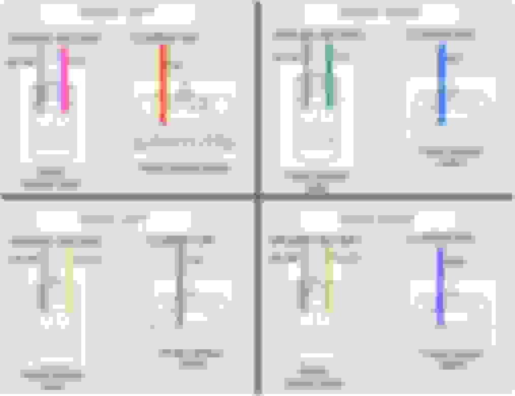
The attached images show location and colors of battery, ground, and illumination wires in the doors.
To disconnect the power window connector, push the release tab sideways, with a small screwdriver, toward the connector, and then withdraw the plug. Fuses can be temporarily pulled to remove battery power from each power window plug while adding the wire taps to battery. All power window fuses are 20A.
Door . . . . . . . . Fuse . . . . Location Front Left . . Door F/L . . . . IP** Front Right . Door F/R . . . . IP** Rear Left . . . Door R/L . . . IP** Rear Right . . Door R/R . . . FB2*** ** Fuse panel under instrument panel *** Under-hood fuse box near wiper fluid filler
To expose a wire, cut back some of the harness sheath material (replace afterward with vinyl electrical tape). I slide a craft stick ("Popsicle stick") into the harness to prevent accidental damage to a wire while cutting the sheath.
Hello, do you have the diagram like this for 2016 Lexus ES 350 Base as well? I am trying to figure out for the ambient lighting install for mine. Thanks a lot

 06-27-23, 10:25 AM