When you click on links to various merchants on this site and make a purchase, this can result in this site earning a commission. Affiliate programs and affiliations include, but are not limited to, the eBay Partner Network.
DIY: Improving brake response with Wilwood Residual Pressure Valves
This is a DIY guide to installing Wilwood Residual Pressure Valves (RPV) on the NX's (or just about any Toyota or Japanese vehicle, even) brake lines to minimize excessive pad retraction whenever the brake pedal is released. A symptom for excessive pad retraction manifests as long pedal travel before any braking happens, despite the pedal being very firm once braking does actually happen. This is not to be confused with having air in the lines, which yields a soft pedal all the way to the end of the braking stroke.
HOW AN RPV MIGHT IMPROVE THINGS: An RPV is designed to flow freely or with minimal resistance one way and provide a set level of resistance the other. By programming a certain level of resistance against brake fluid flow-back, we hope to minimize excessive pad retraction and thereby reduce the slack that the brake calipers have to cover during the next braking activity, thus improving brake response and feel.
THIS IS A DIY IN PROGRESS. I will be constantly updating this main post as I go through the steps myself. The DIY will hopefully be done within the following week. On the other hand, it might be delayed or even fail. (I hope not.)
I'M DONE and the results are great. The lines don't leak, and the pedal is high and plenty responsive. The vehicle coasts to a stop as it did before, indicating no brake drag. Detailed impressions will be posted below once I finish the entire guide.
The finished work clears the factory air box, doesn't touch other parts, and is far from debris danger.
SHOPPING LIST:
These were mostly bought from Amazon, since I can ship a lot of stuff to my country through their international program. I'm sure they're easily available elsewhere.
2 pcs. of Wilwood 2 psi RPVs with 3/8-24 to NPT Fittings Included (P/N 260-13783)
I chose Wilwood RPVs just because they explicitly indicated Made in USA on the product body.
4 pcs. of 10" Pre-flared Copper-nickel (CuNi) 3/16" Brake Lines with 3/8-24 Fitting Threads
I decided to not go about making my own line flarings, having read online how leak-prone novice-made flarings were. Copper-nickel lines are the most durable and rust-proof option after stainless steel while being softer and easier to work with. These are double-flared inverted lines. Don't get the AN single-flared ones. I got 2 packs of 3 each
4 pcs. of Brass 3/8-24 Inverted Female to M10x1.0 Inverted Male Adapters
2 each to mate the new CuNi lines to each of the brake master cylinder's two outlets and another 2 each to mate the new lines to the ABS module's two inlets. I preferred to use brass here, since their threads are soft enough to slightly deform while tightening to improve the seal further - in comparison to stainless steel, at least. Make sure the M10x1.0 sides are inverted and not ISO bubble flares for old European cars. I got a pack of 10
Permatex 54540 Pneumatic and Hydraulic Sealant
Rather expensive for a small bottle of sealant, but this was designed for hydraulic systems and to be non-fouling.
Silicone Line Plugs
These prevent all the brake fluid from running out once you get around removing the factory brake lines. I got them in bulk like
. I reckon you'd do fine with just the latter. The precise kind ended up being useless for the job. Just get the freehand one.
A Friend
Ideally, you don't have to buy one.
A bunch of standard wrenches that I hope whoever plans to do this after me already has.
.
THE GAME PLAN:
Out of the factory, there are 2 lines that go out from the brake master cylinder. The one closer to the firewall snakes down and feeds the ABS module's FL-RR circuit, while the other one snakes down and feeds the FR-RL circuit. We plan to completely replace both of these feed lines with those of our own, with one Wilwood RPV included mid-line for each.
AND FINALLY, STEPS:
Phase 1: Prepping the RPVs
1. Open up the Wilwood RPV packaging and take everything out. Blow hard into the side labeled MC (as in coming from the master cylinder) and try to feel air coming out of the other side labeled OUT. You may have to blow very hard, and that's fine. Flip the RPV the other way and make sure it's harder or even impossible to get air through this time around (we're not high pressure air pumps).
2. Add some of the hydraulic sealant onto the included RPV fittings' second or third threads. Don't get any on the first thread, since you want the RPV internals clean. The fittings already come with sealant, but we're adding some more just to make sure.
3. Install 2 fittings, one on each side, on each RPV. With 2 12mm ratchet socket wrenches, work them against each other until they're very, very tight. The RPV has NPT threads, so go as tight as you can, feeling that you stop right before the threads strip.
4. Let cure for 24 hours.
Phase 2: Protecting the vehicle, evaluating the work area, and removing the air box
As you'll mostly be working from the front left corner of the vehicle, it is important to protect the vehicle paint in this area before commencing work involving brake fluid. Brake fluid is highly corrosive and can damage paint if it comes in contact with it and is left unnoticed for a few minutes. I prepped mine like so:
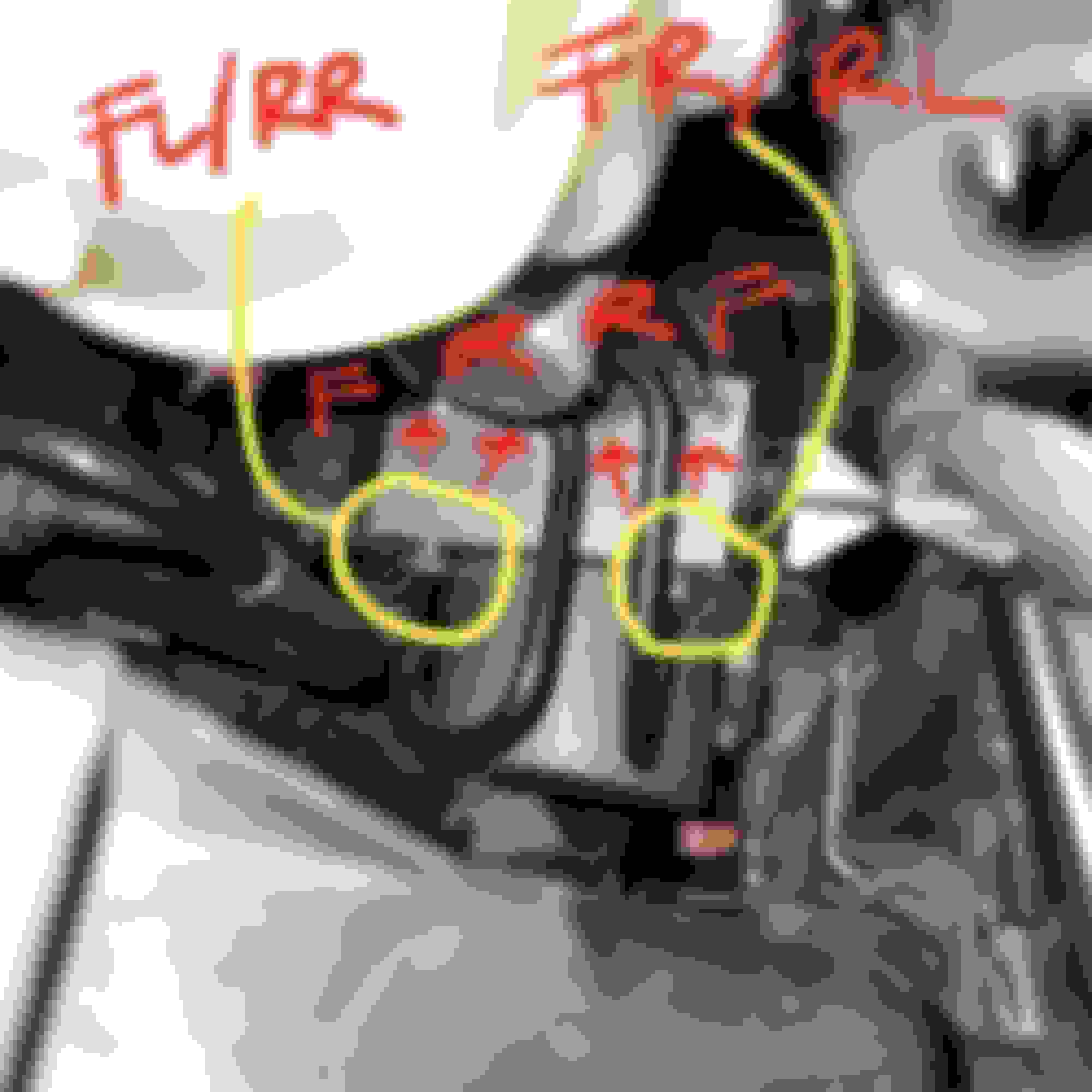
Now that you've got the vehicle paint protected, it's time to familiarize yourself with the clearances behind the factory air box. Keeping these clearances in mind would make bending new brake lines in the following steps a lot easier. The photo below was taken from above the air box. The bottom half of the air box slopes inwards, so there's actually more space than one might think looking at the photo. I've also taken the liberty to mark how brake fluid flows into and out of the ABS module. This will come in handy should you need to troubleshoot the system in the future.
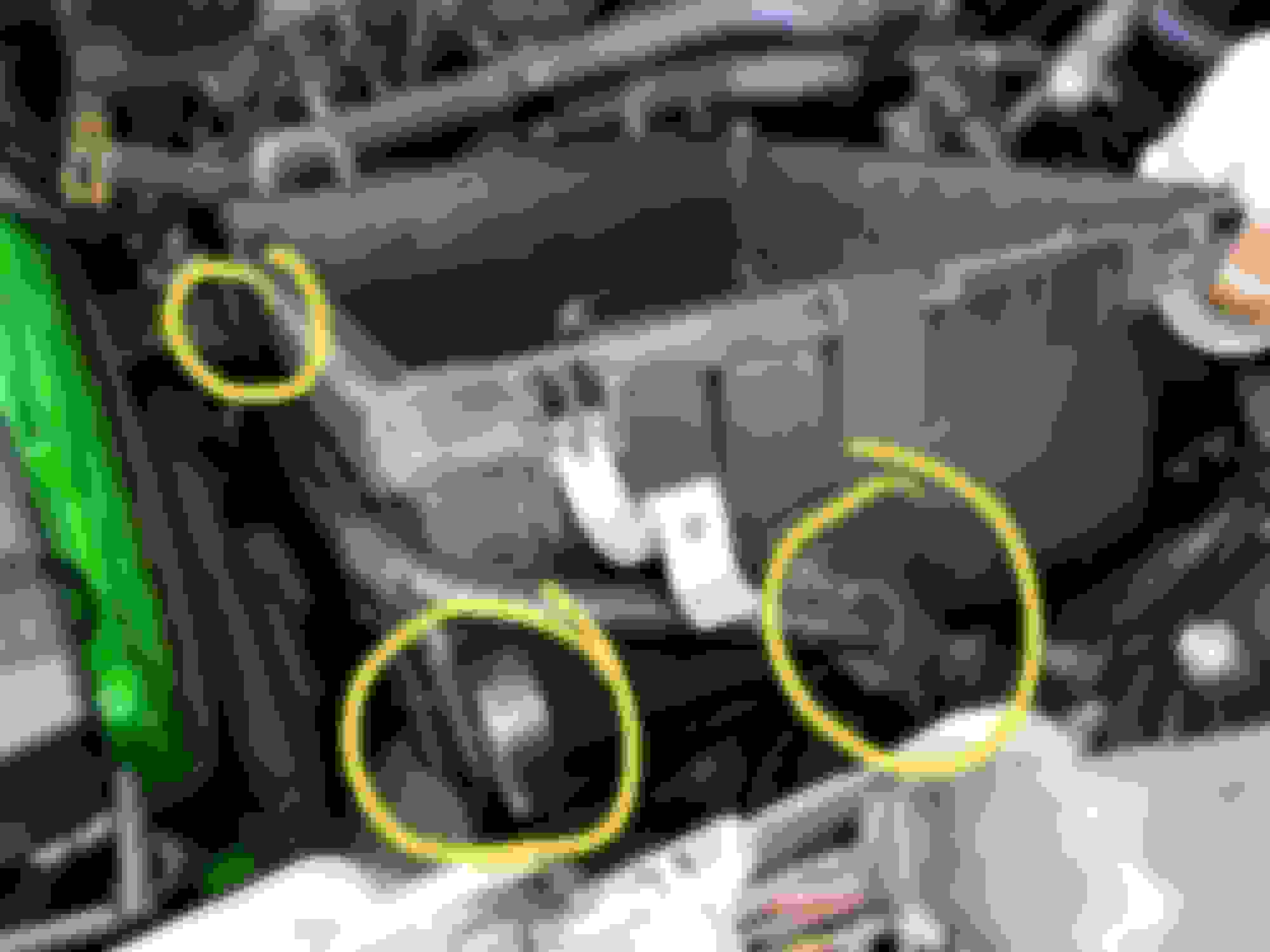
Proceed with removing the upper half of the factory air box. Unlock the 2 clips securing the air filter, unclip the MAF sensor and its wire's clip from the upper air box, loosen the 10mm bolt clamping the assembly to the intake hose, and finally take the upper air box off. The lower air box is secured by 2 10mm bolts to the vehicle body. Remove these bolts. There are 3 clips securing the rest of the MAF sensor wire onto the lower air box, as shown below. Undo the 2 encircled at the bottom, lift the lower air box up, rotate it to a more convenient position, and finally, remove the last remaining clip. The clip on the bottom right of the photo is undone by inserting a flat head screwdriver into the gap.
Phase 3: Removing the factory MC to ABS lines and installing the 3/8-24 to M10x1.0 adapters
Locate the clips by the firewall that hold the two brake lines from the master cylinder in place (leftmost and middle, from where you're standing). With long nose pliers, pinch the "columns" that hold them in place to dislodge them. This will make removing the factory lines a lot easier in the next steps.
STOP! In the next step, working fast is of paramount importance, as brake fluid will be flowing out of the master cylinder. It is important to not empty the reservoir, since that will introduce air into the system, making a bench bleed necessary. During free flow, the brake fluid reservoir level goes down at a rate of about 1/8"/3mm every 3 seconds.
WORK FAST.
HAVE A CLOTH OR CONTAINER READY TO SOAK DRIPPING BRAKE FLUID.
HAVE YOUR 3/8-24 to M10x1.0 ADAPTERS AND SILICONE LINE PLUGS CLOSE.
FAMILIARIZE YOURSELF WITH THE WRENCH SIZE NEEDED FOR EACH COMPONENT BEFORE COMMENCING WORK AND HAVE THEM ALL WITHIN ARM'S REACH.
Ready? Great. Loosen the brake line closest to the firewall first and unscrew it as fast as you can with your fingers. Once it's completely off, yank it out of the way and quickly screw in the 3/8-24 to M10x1.0 adapter, plug it, and tighten it until it stops leaking. Using a smaller plug, block off the line you just got out of the way. This will prevent brake fluid from spilling out once you undo the other side of that line from the ABS module - like biting down a straw to prevent water from going down/out before you point it to someone else and blow out. Unscrew the other side of the line from the ABS module, repeat what was done with the adapter and plug to prevent dirt ingress, and get the first brake line out of the vehicle. TAKE GREAT CARE NOT TO KNOCK THE SILICONE PLUGS LOOSE. Find a water bottle to let the brake fluid in that line drain out to before removing the small silicone plug.
Once things are no longer spilling, tighten the installed adapters to final torque. Factory service manuals specify 10 ft-lbs. torque for MC brake lines, though I tightened mine to much higher than that - maybe around 15 or so - to mold the brass to the factory hardware.
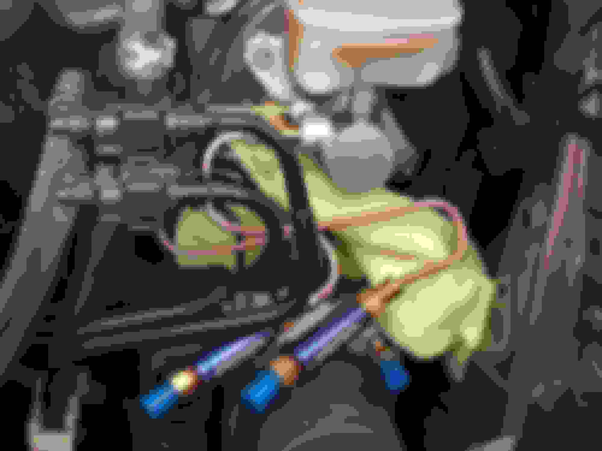
Do the above steps for the other line, and you should have something that looks like this:
Phase 4: Forming and installing new lines until the Wilwood RPV
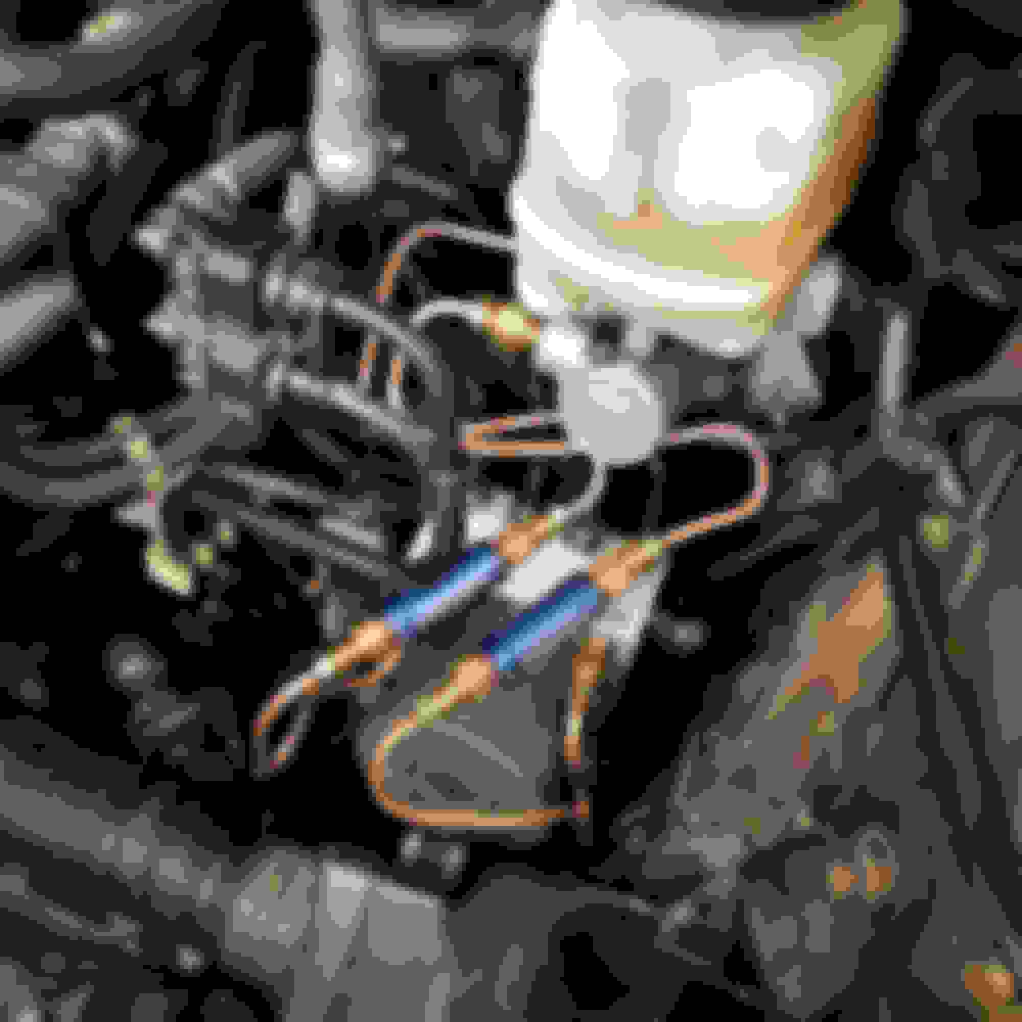
With the lines plugged, you can now form the upper lines in peace. The photo below shows how I did mine. The line closer to the firewall takes a wider "S" to get both RPVs side by side with each other. This layout clears the lower half of the air box and still allows for easy access and tightening of all nuts involved. You shouldn't have removed any of the silicone plugs yet at this point.
1. Form the rough outlines using the freehand tool. The lines are soft enough to be bent/twisted to final shape. When using the freehand line bender, make sure to shift the tool further into the bend, so that you don't do 90 degrees in one go. This prevents the lines from kinking.
2. Once ready, screw in the side of the RPVs labeled MC to the lower end of your new upper lines just tight enough for them to not leak.
TIME TO WORK FAST AGAIN.
3. Remove the silicone plug on the master cylinder that's closer to the firewall and screw in the brake line you just made - only until it stops leaking.
4. Do the same for the line away from the firewall.
END OF WORKING FAST.
5. Loosen the RPV on the lower side of one of your upper lines, leave it be, and don't tighten it back up until brake fluid starts coming out. Repeat this step for the other RPV. This fills the upper lines up with brake fluid and keeps the air you need to "burp" out later on to a minimum.
Phase 5: Forming and installing new lines from the RPV to the ABS module
With the RPVs in place, a minimal amount of pressure is needed for brake fluid to flow out. At this point, the remaining silicone plugs are just there to protect from dust ingress.
1. Form the lower lines that lead to the ABS module as shown below. Note how both ends of the lower lines are the highest points of their sections. This makes pre-bleeding a lot easier in the next step.
3. Remove the silicone plugs and make sure the fittings are free of debris that might get into the brake system.
2. Install the new lower lines you just formed. There's no need to rush, as brake fluid would no longer be freely gushing out of the master cylinder.
Phase 6: Pre-bleeding, final tightening, and leak testing
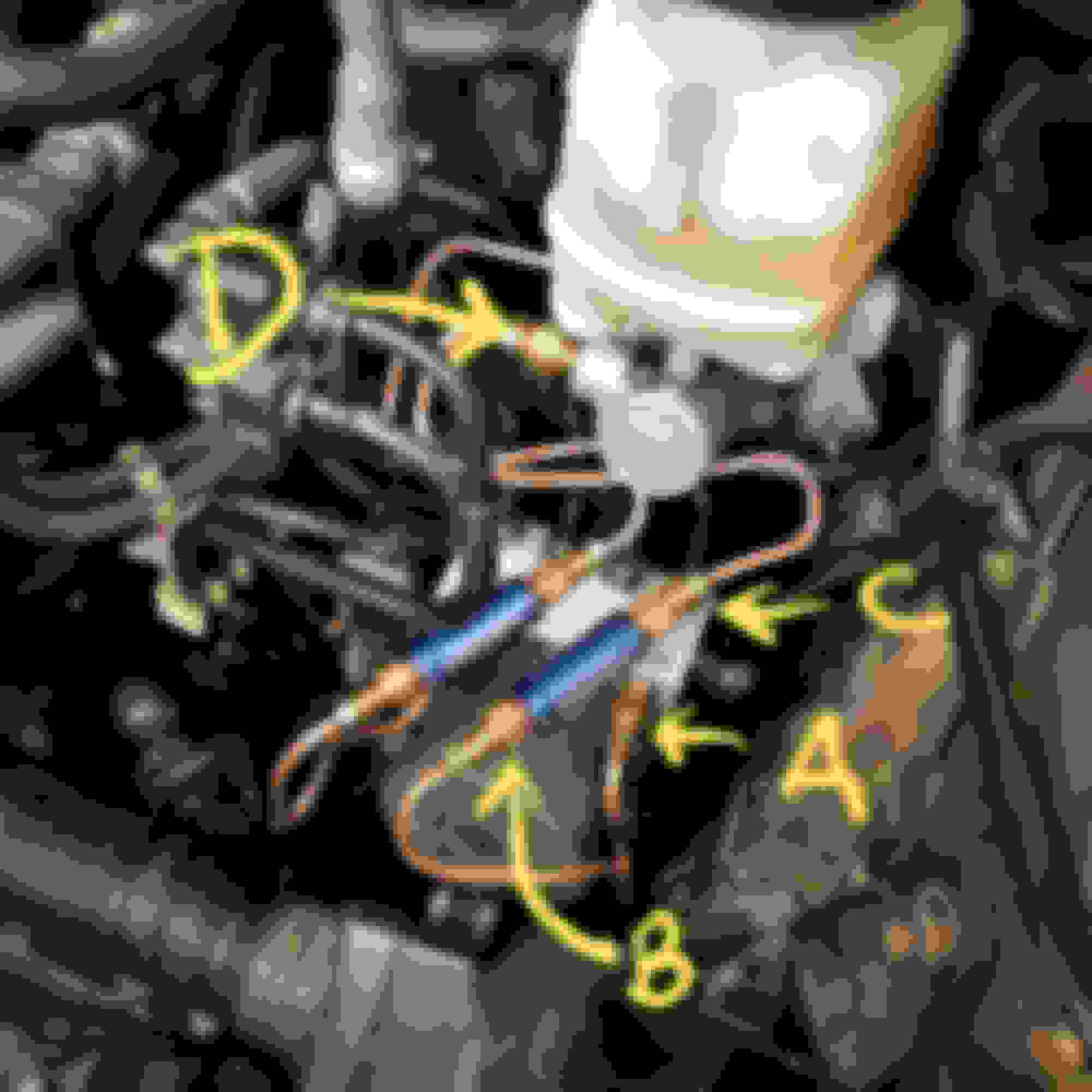
We're now at the home stretch of the project. Bleed points for a single line are shown as A. B, C, and D below, from lowest to highest. Our goal in this stage is to burp all the air out of our new lines, so that we don't have to bleed the brake system at all, unless so desired.
1. Get all connectors tight enough to not leak.
2. The lack of free brake fluid flow in the last phase prevented us from charging the lower lines with fluid the same way we were able to when we formed the upper lines. To purge the air, have a friend pump the brakes until they are the firmest they could get. At this stage, they'd feel really soft, since the entire lower lines have air in them. Once the brakes are no longer firming up, have your friend keep moderate pressure steady on the brake pedal.
3. Crack open bleed point A (ABS module) on one line and wait for brake fluid to start coming out. This indicates that most of the air has been purged out. Tighten bleed point A. Repeat Step 2 and this step for the other line.
4. Repeat Steps 2 and 3 for bleed point A on both lines.
5. Repeat Steps 2 and 3 for bleed point B on both lines TWICE. This purges air that won't flow out of bleed point A.
6. Continue working upwards and repeat steps 2 and 3 for bleed point C on both lines TWICE.
7. Lastly, repeat steps 2 and 3 for bleed point D on both lines TWICE. At this point, the brake pedal should feel really, really firm.
8. Tighten all fittings to roughly 15-ish ft-lbs to form their threads for a tighter seal. When tightening lines, support them with your fingers, so they don't rotate along with the fitting being tightened.
9. Push both lines you just created lower and closer to the firewall one last time to ensure clearance.
10. Fill the brake fluid reservoir up to the MAX level.
After all of the above, have your friend once again pump the brake pedal until it's at its hardest and apply maximum pressure afterwards. If everything was tightened correctly, there shouldn't be brake fluid dripping out of any of the fittings.
Phase 7: Test drive
1. Reverse the air box removal steps and reinstall the air box.
2. If you haven't already, fill the brake fluid reservoir up to the MAX level.
3. Go out for a drive. The brake pedal should be significantly firmer and more responsive by now.
4. Start slow but stomp the brakes whenever you can. Drive around as much as you want doing the same.
5. Inspect the brake fluid level every now and then. If it still lines up to MAX, then you're done with this project.
DRIVING IMPRESSIONS
The brake pedal is now high, firm, and responsive. It used to have 3/4 to an inch of "dead zone" before firming up, despite not having any air in the lines.
Key things I've noticed:
.
With the RPVs installed, the brakes still come on gently but a lot earlier, progressing linearly as greater pedal pressure is applied.
The vehicle's braking capacity greatly increased - not because of some magical increase in friction performance, but rather as a result of all 4 brakes now engaging and sharing load evenly. The front brakes and tires used to be often overloaded, since they seemed to engage earlier and were at threshold way before the rear brakes have reached full capacity. I can only surmise that the rear brake calipers used to retract more than the fronts.
The vehicle still coasts to a stop as it used to, indicating zero brake drag. The wheels can still be turned by hand when the vehicle is lifted off the ground.
With the lack of brake drag, using 4 psi RPVs might actually be feasible and yield better performance.
.
All things considered, this mod may have delivered more than what a switch to stainless steel braided lines could. Definitely a great way to spend ~$80 and 2.5 hours.
Last edited by chezgk; 07-21-20 at 09:02 PM.
Reason: Updates
By removing pad retraction, won't too much brake drag result?
The 2 psi RPVs used in this project shouldn't cause drag, since they simply reduce the excessive retraction engineered into brake caliper piston seals to squeeze the last bit of fuel economy out of a vehicle. 2 psi is an easy finger push and negligible in the context of forces exerted upon the moving parts of vehicles. The vehicle coasts as it used to, and the wheels can still be freely turned by hand when the vehicle's off the ground.
Why 2 psi? What other pressure levels are available?
Wilwood sells 2 psi, 4 psi, and 10 psi variants for their residual pressure valves. They recommend 2 psi for disc brake applications and 10 psi for drum brake applications. They later added the 4 psi variant, stating "Four pound valves can be beneficial in high vibration brake sytems such as off-road or dirt circle track racing." Having read this, I deemed the 2 psi valves to be the most risk-free option for this project.
Why install them after the master cylinder and not the brake calipers on each corner?
Brake fluid temperatures get pretty high during spirited runs, and I fear having the RPVs so close to the calipers would cause their internals to deteriorate. Moreover, having 2 psi of pressure split to 2 lines of the same diameter yields just 1 psi on each line (since cross-sectional area was doubled) - further reducing the risk of brake drag.
Why choose 3/8-24 threads on the new brake lines and have to deal with a bunch of adapters to go back to the M10x1.0 threads that Toyota used for the master cylinder and ABS module?
Only 3/8-24 fittings were available on pre-flared copper-nickel brake lines that I found online. Had they been available with M10x1.0 inverted fittings, this DIY would have certainly gone down a lot simpler.
How did I come up with this idea?
Pretty dumb, actually. I once detached the brake lines from the master cylinder and placed silicone line plugs to prevent dirt from getting into them and then forgot to remove one of them prior to reassembly. With what was effectively a pressure plug stuck in-line, I had fantastic brake feel and response up until the point when the brakes started vapor locking. I tried to look for ways to preserve that instantaneous brake response while allowing the brake pads to release excessive pressure and this was it.
Thanks for a very detailed technical diy on this. I did not even know such a thing existed to fix the lexus/toyota spongy brake issue. I have since googled and read up on residual pressure valves.Planning to get done later this year..
Thanks for a very detailed technical diy on this. I did not even know such a thing existed to fix the lexus/toyota spongy brake issue. I have since googled and read up on residual pressure valves.Planning to get done later this year..
Glad I could be of help. It sure did take a lot of reading about this topic before I decided to embark on this project: from vintage restoration forums, Corvette forums, BMW forums, and even Civic forums. In the absence of anti-knockback springs fitted to multi-piston big brake kits, this was the best option.
Come project time, please make sure you get copper-nickel lines and not pure copper ones.
After seeing the lack of brake drag with 2 psi RPVs, 4 psi ones might just be feasible. They are rather inexpensive at under $25 each, so you could consider getting a set of those together with the 2 psi valves. I've read about some teams even using 10 psi on their race builds, though this probably isn't suited for public roads and long drives. Also make sure you get the Wilwood RPVs shaped like the ones I used. There's an older Wilwood model shaped like a hex lug nut that seems to be really problematic, given what I've read. Those don't have Made in the USA stamped on their bodies, either.
With the tune, suspension work, and this brake line mod, the NX finally drives great. Considering these and all the other more practical factors that made it the first choice for me back in 2015, I don't see myself letting go of the NX soon.
 01-18-20, 02:46 AM