
The nightmare: Aristo Wiring Conversion
 12-28-08, 08:54 PM
#1
BREAKING IDEAS/INFO ON POST #12....
Alright well I am beginning the conversion nightmare that everyone seems to question but no answers are provided. I want to begin a thread that will compile all the information and be a DEEP FAQ. I will look to update this first post with CONFIRMED info. I have done a ton of searching on the internet and I find it amazing that there are multiple threads of how these schematics do not exist but there are companies that are doing the conversions. That means it does exist but no one is providing the data or at least compiling it all in one space...so here it goes. Lets get the conversations rolling.
****I am not trying to take anything from Dr. Tweak or others. I appreciate his help to the community and respect what he does. I am a person that likes to do all his own work, even tedious items like the harness. IF Dr Tweak would provide some info I think that would be really cool especially how to make this work with AEM. ****
Here is a ecu pinout that I have found. It is labeled jspececu.jpg. I BELIEVE it is from an Aristo and to be honest it is the first and only one that i have found that matches my JDM harness pin for pin on the ones that are there and the ones that are not there. This is very frustrating when I try to make sure what I have in comparison to a schematic and they do not match. My 1995 SC300 does not match pin for pin with the FSM that I DL'd from TIS ( Toyota). I am still searching that - I have wires coming out of pin slots where it tells me no wire is or has the dot.
With this above it would make the wiring pretty straight forward. The other item I am working on is making sure that I have right harness pinouts for the body plug. That is what I am also making sure...what are the plugs that I am looking at.I am looking in the manual to see the pinouts but not seeing the plugs (the white ones) I have the pinouts of the orange and 2 grays. Anyone know what the name of them are or the eact function??
Here is another schematic I have found and this one is from a Japense manual as well. This is labeled Aristo (I am working on getting a PDF to be a little more clear) and one of the things that I noticed from a quick glance is that some of the pin locations are different.

I am making an excel sheet so it is easy to read what to connect with what...however I got to get the ball moving first and want some data dumping here please.
Alright well I am beginning the conversion nightmare that everyone seems to question but no answers are provided. I want to begin a thread that will compile all the information and be a DEEP FAQ. I will look to update this first post with CONFIRMED info. I have done a ton of searching on the internet and I find it amazing that there are multiple threads of how these schematics do not exist but there are companies that are doing the conversions. That means it does exist but no one is providing the data or at least compiling it all in one space...so here it goes. Lets get the conversations rolling.
****I am not trying to take anything from Dr. Tweak or others. I appreciate his help to the community and respect what he does. I am a person that likes to do all his own work, even tedious items like the harness. IF Dr Tweak would provide some info I think that would be really cool especially how to make this work with AEM. ****
Here is a ecu pinout that I have found. It is labeled jspececu.jpg. I BELIEVE it is from an Aristo and to be honest it is the first and only one that i have found that matches my JDM harness pin for pin on the ones that are there and the ones that are not there. This is very frustrating when I try to make sure what I have in comparison to a schematic and they do not match. My 1995 SC300 does not match pin for pin with the FSM that I DL'd from TIS ( Toyota). I am still searching that - I have wires coming out of pin slots where it tells me no wire is or has the dot.
With this above it would make the wiring pretty straight forward. The other item I am working on is making sure that I have right harness pinouts for the body plug. That is what I am also making sure...what are the plugs that I am looking at.I am looking in the manual to see the pinouts but not seeing the plugs (the white ones) I have the pinouts of the orange and 2 grays. Anyone know what the name of them are or the eact function??
Here is another schematic I have found and this one is from a Japense manual as well. This is labeled Aristo (I am working on getting a PDF to be a little more clear) and one of the things that I noticed from a quick glance is that some of the pin locations are different.
I am making an excel sheet so it is easy to read what to connect with what...however I got to get the ball moving first and want some data dumping here please.
Last edited by ICONYQ; 04-17-09 at 03:31 PM.
 12-28-08, 09:23 PM
#2
Lead Lap

Join Date: Jan 2006
Location: Ronert Park, CA
Posts: 735
Likes: 0
Received 0 Likes
on
0 Posts
i was looking into doing the conversion myself but ended up paying dr tweak, but here is problems i ran into, not enough aristo wiring out there and making all the body plugs work, so you use stock GE small plug to ECU and wire up those, delete the track plug harness all together, maybe take some wires from it. your going to have to identify what every wire does going to the body harness. some i found by looking at the sc300 wiring diagram from the cluster to the body plugs down by the ecu, some wires are for water temp gauge, speedo if you have a manual, oil level sensor, basicly alot of lights for the gauge cluster. something you also have to do the cluster to make the tach work. not sure what it is. other body plugs could be switch for when you put in into reverse to turn the rear lights on. then you need power for the efi relay, looks like you just use the efi power plugs from the GE harness. 2 wires that go to a body plug will be for heater control valve. this is what i noticed when pluggin in my harness and doing my own research. there are no body plugs in the aristo harness. so recap on some wires for body plugs,
water temp,tach signal, heater control, reverse lights, speed signal for trans. alot of this info you can find on the us harness diagram.
water temp,tach signal, heater control, reverse lights, speed signal for trans. alot of this info you can find on the us harness diagram.
12-29-08, 06:53 AM
#3
How different are the Supra ECUs to the Aristo ECUs? I have access to both Supra and SC wiring diagrams and so far they look similar but pin numbers look to be a little different comparing the ECU pinouts and the wiring diagram. I can try deciphering it later today when im off of school.
12-29-08, 08:26 AM
#4
the supra and aristo are close but not identical. I can tell you that when I compared the empty spots to the filled spots on the supra pinout above it was spot on. However I have read that the pins have been moved around. As far as the Aristo pinouts I see they are really moved around and I am still missing some from the engine diagram.
I have found off supraforums a post where it has the aristo wiring pinouts but having a hard time linking the ECT and engine pinouts. Engine is using W and V (opposed to A and B in the US manuals) and the ECT has O, P, Q, R, S as the plug distinguisher - I WAS LOOKING AT THE 97+ and not the 91. If you need 97 data use the spreadheet. I have made a cleaner spreadsheet on the next post which is now all coming together.
I have began mapping these out in an excel. to try to get them in a neat organized manor but I am still not seeing a complete pinout...
The excel sheet is a CRUDE mockup. I have not made it pretty. I will when I am done. However if you compare this excel against the US spec pinout on SF from the link above they are close...oh so close - minus the missing wires.
Last edited by ICONYQ; 12-29-08 at 11:22 AM.
12-29-08, 11:19 AM
#5
Alright...well here is a cleaner sheet that compares:
Aristo electric drawing vs. US Supra vs. JDM Supra
This pin-out is taking the standpoint of what is on a 1991 Artisto. This is from the electrical drawings found off supraforums which are from the manual.
Black = on the electrical drawing - I am looking at this as confirmed.
Black square = no wire in the pin location per Aristo/US Supra/JDM supra electric drawing.
Red = on Supra JDM pin-out but not showing on Aristo electrical drawing.
***Does not mean it is supposed to be on the Aristo just highlighting the discrepancy ***
I am looking to verify the red at this point
Last edited by ICONYQ; 12-29-08 at 11:58 AM.
12-29-08, 12:19 PM
#6
much props for doing this...It would be awesome if we had a simple table to look at an could do our own wiring.
Ill be tackling this job as well in February and ill be able to help donate some info then....
Ill be tackling this job as well in February and ill be able to help donate some info then....
Trending Topics
12-29-08, 03:22 PM
#8
Lead Lap
Join Date: Jan 2006
Location: Ronert Park, CA
Posts: 735
Likes: 0
Received 0 Likes
on
0 Posts
there is also somewhere on here that dr tweak posted somewhat on how to get the a/c working, now you just have to figure out all the connector plug names at the passanger kick pannel. there is a orange one, grey one and some white ones. here are some connectors in the kick pannel. when you get your GE harness off the vehicle you can just ohm the wires for speedo. i cant find them yet, here are some that i found. you can also ohm the heater vsv soilnoid which is only 2 wires
reverse lamps on IK1 WIRE 11 R-B ALSO 1J1 WIRE 10 Y
tach is plug 1k1 wire 8 color B. temp for cluster is 1k1 wire 9 y-g
reverse lamps on IK1 WIRE 11 R-B ALSO 1J1 WIRE 10 Y
tach is plug 1k1 wire 8 color B. temp for cluster is 1k1 wire 9 y-g
12-29-08, 03:30 PM
#9
Lead Lap
Join Date: Jan 2006
Location: Ronert Park, CA
Posts: 735
Likes: 0
Received 0 Likes
on
0 Posts
so now you just get the water temp signal from the aristo wiring and wire that to wire 9 in 1k1, find tach signal from aristo harness connector 1k1 wire 8. reverse lamps are easy, if you have a GE harness out of the car its gonna be alot easier
12-30-08, 11:34 AM
#10
Okay well I have had some fun as of late. Let me first say that this wire harness was messed with before. I am getting my own ideas of what the car went through before it was provided to the dealer on a trade in but I will keep those to myself. Just for an idea: The knock sensors are clear speaker wire coming out from the ECU plug.
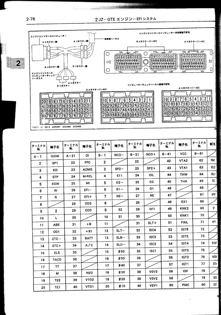
this is the pinouts that I got for the 2JZGE that I pulled off the MAP-ECU forum. I made a pinout of this and compared it against my ECU plug....


Gray box = no pin allocated per FSM
Yellow box = no pin allocation per FSM but my harness has a wire in it
this is the pinouts that I got for the 2JZGE that I pulled off the MAP-ECU forum. I made a pinout of this and compared it against my ECU plug....
Gray box = no pin allocated per FSM
Yellow box = no pin allocation per FSM but my harness has a wire in it
now I do think there are some errors because you will see that there are no pin allocation on the ECU connection but they connect to a body harness. For example Connection A Pin 17 is TT ( Data Link Connector 2) and it connects to IK1. I have a wire from IK1 but on the pinout above it says no wire is supposed to be there.
my big concerns are the items like ECU A Pin 3 has a blue wire coming out of it but on all pinouts (Supra - US And JSM, 2jzGE) there is not line supposed to be there. However it is there are the Aristo --> it is the KD.
my big concerns are the items like ECU A Pin 3 has a blue wire coming out of it but on all pinouts (Supra - US And JSM, 2jzGE) there is not line supposed to be there. However it is there are the Aristo --> it is the KD.
12-30-08, 11:38 AM
#11
Here is the work I did on the body plugs. I have notated where the wires connect into from one plug to anoter. If there is nothing in the box that is because it is a cut wire and will be going back into the harness. Now the next step will be to compare these to the body harness diagram that I have from the Aristo and mix and match the lines. This will make matching it up very easy. I will post the matches later.
04-17-09, 03:27 PM
#12
okay guys to drum up an old thread...I do not need the harness this time but still looking at ways to do this and still trying to help the community out ( I took the easy way and got a USDM TT harness  )
)
Why is the conversion always from the standpoint of extending the JDM harness and figuring out the body plugs. Why do we not take the GE harness and add pins to it from the JDM harness or just make full new lines...NO SOLDER!! Then all you would need to do is swap out connectors and that mainly can be done with repinning. I would love to get my hand on a spare aristo and ge harness. I have the ECU and could test it.
Again I in no way mean to take anything away from our vendors on this site I am just trying to help the DIY guys.
BTW Wanganstyle thank you for getting the thought juices flowing again after your conversion.!!!!
I posted it in PDF so no one could steal it --> Just playing. I did that so no one would be worried about virus. Also cleaner. I did this in excel and can send anyone the xls file.
) Why is the conversion always from the standpoint of extending the JDM harness and figuring out the body plugs. Why do we not take the GE harness and add pins to it from the JDM harness or just make full new lines...NO SOLDER!! Then all you would need to do is swap out connectors and that mainly can be done with repinning. I would love to get my hand on a spare aristo and ge harness. I have the ECU and could test it.
Again I in no way mean to take anything away from our vendors on this site I am just trying to help the DIY guys.
BTW Wanganstyle thank you for getting the thought juices flowing again after your conversion.!!!!
I posted it in PDF so no one could steal it --> Just playing. I did that so no one would be worried about virus. Also cleaner. I did this in excel and can send anyone the xls file.
04-17-09, 10:30 PM
#13
Lead Lap
Join Date: Jan 2006
Location: Ronert Park, CA
Posts: 735
Likes: 0
Received 0 Likes
on
0 Posts
well assuming you bought a aristo motor set with the harness, then i guess it wouldnt be to bad to mod the GE harness. just add the coil plugs, and ignitor wires, crank sensor, cam sensor and you could possibly just get the car started at the bare minimum with that stuff
 04-18-09, 07:42 AM
#15
yea the PDF shows that...I am pointing out that it would limit alot of work and make the swap easier. Majority of the issue is sitting trying to figure out what the gray plug actually breaksdown to. Using the GE harness you would not have to worry about that puzzle.
well assuming you bought a aristo motor set with the harness, then i guess it wouldnt be to bad to mod the GE harness. just add the coil plugs, and ignitor wires, crank sensor, cam sensor and you could possibly just get the car started at the bare minimum with that stuff