
Low boost, low budget 1UZ single turbo setup
 12-18-10, 09:24 AM
#31
Instructor

It's sure nice to have some def needed information as I've been trying to find the IAC wiring for a while. I am honestly not to concerned with running the factory IAC as there are so many options out there. I do see what your saying about the IAC not working unless there's in an input because how would it know how/when/what to adjust to stay running or if it's doing it's job, good point. Maybe I need to just wire the OE ecu to just have basic inputs like RPM, other than that I'm pretty sure it should at least idle, and it could possibly need a coolant temp sensor to possibly operate high idle, not too sure because it doesn't have spark or fuel capabilities anymore. I wonder how the MS would respond to a fluctuating IAC controlled by a parrallel ecu, you would think it wouldn't be a problem as the MS controls fuel/spark according to RPM/Map sensor (that's how I've written my .msq), right?
I'm not the biggest fan of having turbos underneath the car. I'm sure a sump pump will work, but I just think their something to be said about a monstrous single turbo as soon as you pop the hood. I.E. When your looking under the hood of a Supra, what's the first thing you look for?
I'm not the biggest fan of having turbos underneath the car. I'm sure a sump pump will work, but I just think their something to be said about a monstrous single turbo as soon as you pop the hood. I.E. When your looking under the hood of a Supra, what's the first thing you look for?
 12-18-10, 09:36 AM
#32
Instructor
thats a nice way to do it, sounds like it should work pretty reliably.
different engine, same problem.
If I turn the boost up more ill risk breaking my w58.
hopefully i will get rid of that problem soon and upgrade, maybe when it gets warmer outside.
on my aem options for the idle valve it has 4 steppers for idle. i think our cars use a similar valve.
different engine, same problem.
If I turn the boost up more ill risk breaking my w58.
hopefully i will get rid of that problem soon and upgrade, maybe when it gets warmer outside.
on my aem options for the idle valve it has 4 steppers for idle. i think our cars use a similar valve.
Yep, it's the same on the MS. When building it, it has to have a few things done differently to run a stepper IAC instead of running a PWM IAC, or visa versa. I must admit, when I first looked at the 6-wires, I was a bit turned off and was just going to leave it unplugged, crack the throttle plate and let it be and adjust accordingly. But I don't like building this whole thing, and leaving it have some shotty idle, I'm sure you guys understand. I think with a little bit of patients we'd be able to get something going. I guess we just need to find out which one is A1, A2, B1 and B2, which two aren't connect?
12-18-10, 10:56 AM
#33
That's pretty sweet to see it broken down like that. From the IS300 guys, I've heard 350rwhp is about the limit, than the cause literally starts to split in half (hearsay, but have seen a few pictures).
Yep, it's the same on the MS. When building it, it has to have a few things done differently to run a stepper IAC instead of running a PWM IAC, or visa versa. I must admit, when I first looked at the 6-wires, I was a bit turned off and was just going to leave it unplugged, crack the throttle plate and let it be and adjust accordingly. But I don't like building this whole thing, and leaving it have some shotty idle, I'm sure you guys understand. I think with a little bit of patients we'd be able to get something going. I guess we just need to find out which one is A1, A2, B1 and B2, which two aren't connect?
Yep, it's the same on the MS. When building it, it has to have a few things done differently to run a stepper IAC instead of running a PWM IAC, or visa versa. I must admit, when I first looked at the 6-wires, I was a bit turned off and was just going to leave it unplugged, crack the throttle plate and let it be and adjust accordingly. But I don't like building this whole thing, and leaving it have some shotty idle, I'm sure you guys understand. I think with a little bit of patients we'd be able to get something going. I guess we just need to find out which one is A1, A2, B1 and B2, which two aren't connect?
12-18-10, 03:38 PM
#34
Instructor
12-19-10, 01:12 PM
#36
Hey guys,
Noticed you talking about the IAC valve. Here is what I know about it, mine works very well with the Adaptronic ECU.
The motor has 125 steps. There are 6 wires but two of them are power and you do not need to mess with these. Each power wire connects to 2 coils inside the valve's motor. The other 4 wires are ground / control wires for the 4 coils (hence the term "4-wire") inside the IAC motor and are connected to isc1-isc4 on the ECU, pins 32-35 on my 95. This can been seen in the wiring diagram. The EGR motor works in the same exact way judging by the diagram.
I wired mine the way shown on Lextreme SC400 wiring info for the Adaptronic. Well, that didn't work. I had to try a few different combinations for the Adaptronic outputs (in the software) to get it to work. I took off the valve and swapped the outputs around (again, in the software) and changed the "max steps" back and forth from 0-125 untill I could see it closing at 0 and opening as I went towards 125. I actually figured it out backwards first.
Not sure if it will help but mine is setup:
ISC1 pin 35 violet / red wire goes to idlestepper 4 output of the Adaptronic.
ISC2 pin 34 lightgreen / black goes to idlestepper 3 output of the Adaptronic.
ISC3 pin 33 green / yellow goes to idlestepper 1 output of the Adaptronic.
ISC4 pin 32 lightblue / white goes to idlestepper 2 output of the Adaptronic.
Hope this helps you guys.
KC
12-19-10, 05:13 PM
#37
Yea I'll have to try again on the IAC tomorrow. I finally figured out why my car felt like it was only half-running! Somehow during the wiring process, I managed to unplug the passenger side coil power and didn't see it until today....so relieved. Can't believe I had everything done in a day and couldn't figure something so stupid out for a week. Oh well I am just glad it runs right. It pulls so much harder and drives so much better than stock with just the speculative map I made for it without ANY wideband tuning. Definitely already worth the money and time spent building it.
PS: KC, I was actually trying to wire mine after yours last time I attempted the IAC. lol I can't believe that is the hardest thing about standalone! Figures.
Oh well I am just glad it runs right. It pulls so much harder and drives so much better than stock with just the speculative map I made for it without ANY wideband tuning. Definitely already worth the money and time spent building it.PS: KC, I was actually trying to wire mine after yours last time I attempted the IAC. lol I can't believe that is the hardest thing about standalone! Figures.
12-19-10, 05:25 PM
#38
Yea I'll have to try again on the IAC tomorrow. I finally figured out why my car felt like it was only half-running! Somehow during the wiring process, I managed to unplug the passenger side coil power and didn't see it until today....so relieved. Can't believe I had everything done in a day and couldn't figure something so stupid out for a week. Oh well I am just glad it runs right. It pulls so much harder and drives so much better than stock with just the speculative map I made for it without ANY wideband tuning. Definitely already worth the money and time spent building it.
PS: KC, I was actually trying to wire mine after yours last time I attempted the IAC. lol I can't believe that is the hardest thing about standalone! Figures.
Oh well I am just glad it runs right. It pulls so much harder and drives so much better than stock with just the speculative map I made for it without ANY wideband tuning. Definitely already worth the money and time spent building it.PS: KC, I was actually trying to wire mine after yours last time I attempted the IAC. lol I can't believe that is the hardest thing about standalone! Figures.
Compare the above pairing to what's shown on my diagram and you'll see the difference.
KC
01-02-11, 02:01 PM
#39
Instructor
Hey guys,
Noticed you talking about the IAC valve. Here is what I know about it, mine works very well with the Adaptronic ECU.
The motor has 125 steps. There are 6 wires but two of them are power and you do not need to mess with these. Each power wire connects to 2 coils inside the valve's motor. The other 4 wires are ground / control wires for the 4 coils (hence the term "4-wire") inside the IAC motor and are connected to isc1-isc4 on the ECU, pins 32-35 on my 95. This can been seen in the wiring diagram. The EGR motor works in the same exact way judging by the diagram.
I wired mine the way shown on Lextreme SC400 wiring info for the Adaptronic. Well, that didn't work. I had to try a few different combinations for the Adaptronic outputs (in the software) to get it to work. I took off the valve and swapped the outputs around (again, in the software) and changed the "max steps" back and forth from 0-125 untill I could see it closing at 0 and opening as I went towards 125. I actually figured it out backwards first.
Not sure if it will help but mine is setup:
ISC1 pin 35 violet / red wire goes to idlestepper 4 output of the Adaptronic.
ISC2 pin 34 lightgreen / black goes to idlestepper 3 output of the Adaptronic.
ISC3 pin 33 green / yellow goes to idlestepper 1 output of the Adaptronic.
ISC4 pin 32 lightblue / white goes to idlestepper 2 output of the Adaptronic.
Hope this helps you guys.
KC
Noticed you talking about the IAC valve. Here is what I know about it, mine works very well with the Adaptronic ECU.
The motor has 125 steps. There are 6 wires but two of them are power and you do not need to mess with these. Each power wire connects to 2 coils inside the valve's motor. The other 4 wires are ground / control wires for the 4 coils (hence the term "4-wire") inside the IAC motor and are connected to isc1-isc4 on the ECU, pins 32-35 on my 95. This can been seen in the wiring diagram. The EGR motor works in the same exact way judging by the diagram.
I wired mine the way shown on Lextreme SC400 wiring info for the Adaptronic. Well, that didn't work. I had to try a few different combinations for the Adaptronic outputs (in the software) to get it to work. I took off the valve and swapped the outputs around (again, in the software) and changed the "max steps" back and forth from 0-125 untill I could see it closing at 0 and opening as I went towards 125. I actually figured it out backwards first.
Not sure if it will help but mine is setup:
ISC1 pin 35 violet / red wire goes to idlestepper 4 output of the Adaptronic.
ISC2 pin 34 lightgreen / black goes to idlestepper 3 output of the Adaptronic.
ISC3 pin 33 green / yellow goes to idlestepper 1 output of the Adaptronic.
ISC4 pin 32 lightblue / white goes to idlestepper 2 output of the Adaptronic.
Hope this helps you guys.
KC

So, we have a 4-wire stepper motor with 125 steps. The remaining two wires power the coils, so these should be hooked up to 12v? Than once the coils are energized, the ecu grounds the different circuits via the 4 wires?
01-10-11, 09:13 PM
#40
Driver
Join Date: Jan 2011
Location: KS
Posts: 125
Likes: 0
Received 0 Likes
on
0 Posts
I just got my SC400 so I don't have the wiring manuals yet. Is the 1UZ IAC like the 1MZ IAC? I ask because I succesfully 'Squirted the 1996 1MZ in my old 1993 MR2. I used MS v3.0 board, but v1 CPU with the stock 36-2 crank trigger. 100% Toyota electronics install on my MZ.
Basically the stock 1MZ IAC had 3 wires. +12, IAC-O (Open) and IAC-C (Closed). What I had to do was wire the IAC-C side to ground with a resistor so it was closed at all times. I then wired the IAC-O to the MS and it would "fight" the closed coil to open it up. I used a 40 ohm / 50 watt resistor to do this, IE: a really nice one with aluminum body for cooling.
Warmed up and idled like stock.
01-10-11, 09:17 PM
#41

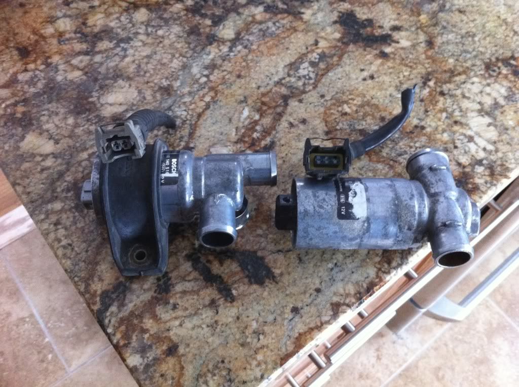
It becomes a little clearer when someone can easily explain something to you, thank you. I have actually been working on my friends Volvo 850 and after looking at his IAC, I decided to pull a few in the local junk yard. I pulled a 95' 850 IAC and I decided to pull an older 89' 740 IAC as well. 850 is a 3-wire, and 740 is a 2-wire. But after having you break it down like you did, I think it is a bit easier to work with instead of having to fab something else up.
So, we have a 4-wire stepper motor with 125 steps. The remaining two wires power the coils, so these should be hooked up to 12v? Than once the coils are energized, the ecu grounds the different circuits via the 4 wires?
So, we have a 4-wire stepper motor with 125 steps. The remaining two wires power the coils, so these should be hooked up to 12v? Than once the coils are energized, the ecu grounds the different circuits via the 4 wires?
Badass, so those volvo's have an external IAC setup... this is perfect for someone who does not want to use the stock intake manifold, me. Should I go for the 2 wire or 3 wire setup if given the option at the next yard hunt?


Thread
Thread Starter
Forum
Replies
Last Post