When you click on links to various merchants on this site and make a purchase, this can result in this site earning a commission. Affiliate programs and affiliations include, but are not limited to, the eBay Partner Network.
I have been looking for an easy and comprehensive guide to wiring up a 2jzgte vvti swap into any car, but I have not been able to find any. So I have decided to make my own write-up. I have done my swap in a 1997 sc300 because of mass compatibility with the engine swap and the car as they already come from the factory with a 2jz in it, albeit a GE non vvti. The difficulty with this swap is all the wiring. Other swaps like the 1jzgte non vvti are much easier to conduct on this particular vehicle due to almost plug and play compatibility. Just the stock 1jzgte engine harness needs an extension and it can plug right into the body harness of the car in the passenger foot well, no merging necessary.
This particular 2jzgte vvti swap that I am using is out of a second generation Toyota aristo v300 from Japan. Its body harness is meant to plug into the engine bay and the ecu is meant to rest in an ecu box in the engine bay of a GS300 or IS300. I will be using the ecu box out of an is300 to house the ecu in the engine bay as I do not plan on extending the aristo harness for the ecu to fit in the foot well. What I will be doing is using two external relays and relay plugs to power the engine swap from the use of the stock electrics of the vehicle. Also the goal is to get all dashboard functions working with the engine swap like factory. This includes but not limited to: low oil light, check engine, battery discharge, PRNDL indicator lights, coolant temp gauge, tachometer, speedometer, fuel level (works off the body harness, no splicing needed), reverse lights, AC, heat, etc.
DISCLAIMER: I DO NOT TAKE ANY RESPONSIBILITY FOR ANY DAMAGE OR LOSS TO YOUR ENGINE/CAR/DRIVETRAIN, THIS WRITE UP IS PURELY FOR INSTRUCTIONAL PURPOSES, USE AT YOUR OWN RISK.
To power the ECU, you will need two additional ECU plugs, plugs F59 and F60 from either a 2nd gen GS300, or an 01 IS300. These plugs are what allow the body of the car to interact with the ECU. The other three plugs B1, B2, and B3 are what allow the ECU to communicate with the engine swap alone and allow proper functionality of the engine. We will not be touching these three plugs, only plugs F59 and F60. Refer to the picture below for the pinouts.
I have a short somewhere in my body harness for my main relay, so I will be using two external relays to power the swap. I have bought two bosch 40 amp relays, you can get them at any electronics store. I bought them from Worldpac auto supplier warehouse. Using these two external relays method will allow you to get this swap running in any vehicle regardless of make. As long as the body harness is complete on the vehicle this swap is being transplanted in, you will be able to wire this swap with ease. All that change from vehicle to vehicle is the black signal wires for the relays that allow them to be switched on. Other than that, the relay wiring remains the same for every car.
The relays get wired up as follows. The two trigger signal wires from plug
90980 – 10813 (GRAY PLUG)
Pins 2 goes to the black wire (signal wire) on relay 1, and pin 7 goes to the black wire (signal wire) on relay 2
(IF using your stock MAIN RELAY, use pin 2 as a signal, and run it to PIN 8 on plug 10897)
The brown wires go to ground, crimp a ring terminal on the end of each of the brown wires and then bolt them down anywhere on the chassis (try and sand the surface of where the brown wires are being ground to for a solid connection).
The blue wire on relay 1 goes to pins 8,9,10,16, of plug F60
(B+, B2+, main relay, ignition switch)
The blue wire on relay 2 goes to pins 7 and 8 of plug 11527 (coil pack power, injector power), and to the fuel pump wire.
also you WILL NEED to run plug BF2 pin 9, and BF3 pin 9 to the same blue wire on the relay.( THIS PROVIDES POWER TO THE MAIN SENSORS, INCLUDING MAF, O2 SENSOR, and other various sensors. without these two wires getting power, the engine will run in limp mode)
The “fuel pump wire” is a wire that needs to be ran directly to the fuel pump positive terminal. You have to find that wire somewhere coming out of your gas tank. In the sc300, the gas tank is in the trunk, and it sits behind plastic trim directly behind the rear seats. There is a plug coming off of it with a green/white wire. That green/white wire is the fuel pump positive wire. You have to strip the wire, wrap the new “fuel pump wire” around the metal portion of the wire, solder the connection, and wrap it with heatshrink then electrical tape. Run that wire all the way up through the front of the car along the same path as the battery relocation wire and attach that wire to the blue wire on relay 2. This should feed enough power to the injectors, coil packs, and fuel pump.
I have a Denso mark4 supra twin turbo fuel pump installed as an upgrade over the stock sc300 fuel pump. This should provide enough flow for stock twins that im running right now.
Yellow wire on relay 1 and relay 2 goes battery power via 4 gauge wire coming off of the distribution block. Your choice which gauge wire you want to use, I prefer 4 gauge simply because it ensures adequate power to all components.
Now that the relays are taken care of, a I did a battery relocation to the trunk because my ecu box will be placed in the battery’s old location. So I used 0 gauge wire and ran it to the trunk through the firewall and wired it to a distribution block up front in the engine bay. I grounded the negative terminal in the bay to the chassis, and grounded another piece of 0 gauge wire to the chassis in the trunk to act as the negative terminal. The distribution block in the engine bay has two four gauge wire running out of it, one wire provides power to the fuse box, the other 4 gauge wire provides power to the starter cable, relays 1 and 2 switched power, and battery memory (F60 pin 1).
For the fuse box, I connected a ring terminal to the end of the 4 gauge wire and ran it up to the fusebox and bolted it down to the fuse box terminal.
^distribution block
For the starter cable/battery memory/relays1&2, I crimped ring terminals to the 4 gauge wire coming off the distribution block, a ring terminal on F60 pin 1, ring terminals on relays 1&2 yellow wires, and there is already a ring terminal on the starter cable, I just bent the terminal from 90 degrees to straight with a set of pliers. Then I stuck a bolt through all of the terminals and attached a locking nut to the other side and tightened it down. Then wrapped loom around it and wrapped it in shrinktubing and electrical tape.
For the etcs-I function, electronic throttle body, pin 7 on plug F60 is wired to pin 4 on plug 10897 off the fusebox body harness. There is a 30 amp fuse in place in the slot labeled EFI, this fuse needs to be replaced with a 15 amp fuse for the etcs-I throttle body requires a 15amp fuse to function correctly. (if you find another pin that’ll work for the etcs-I wire, then go ahead and use it, as long as it has power when the key is in the “ON” position and you are able to run a 15amp fuse inline.)
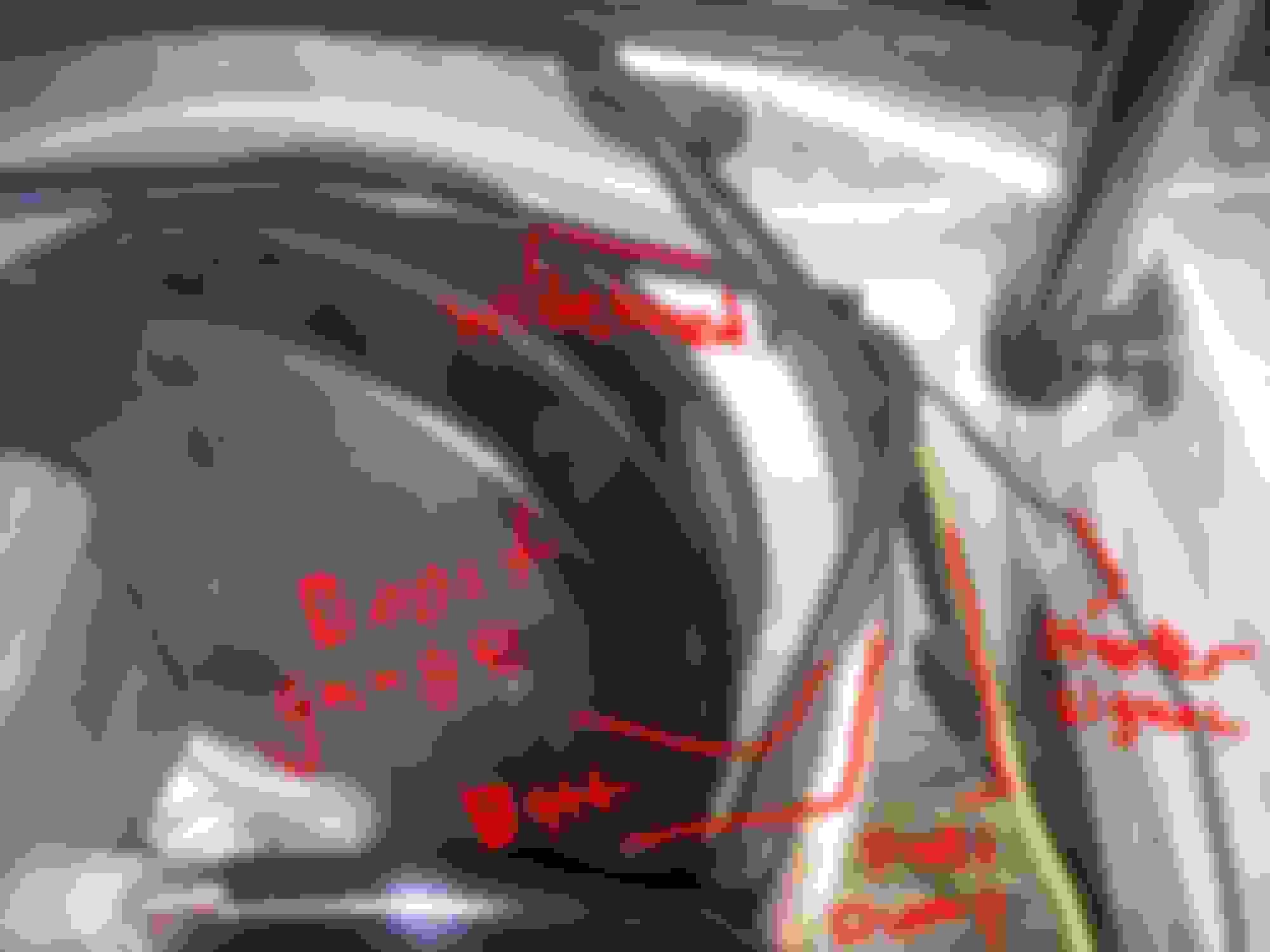
For the temperature gauge, you will need to either buy a lexus sc300 (pre-1998) coolant temperature SENDER (not sensor). It’s a 14mm hex fitting with a single pin plug at the end of it. this is what will send the temperature reading to the cluster for the temp gauge needle. That plug will need to be cut off your stock 2jz-GE engine harness, or you will need to source one for your particular vehicle. The connector will need a wire soldered to it, and that wire will be ran to connect to pin 9 on the orange 23 pin plug in the footwell (10921)
(insert picture)
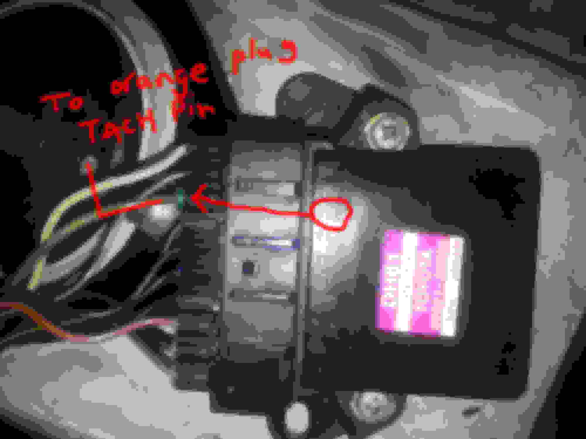
For the tachometer you will need to go to your igniter, and look at the TAC pin. Sometimes the igniter connector has that particular pin capped off. So you will need to remove that cap and run a pinned wire to it with a weather seal on it and install it within the connector. That wire will need to be soldered to a long wire that will run to the passenger foot well and it will be soldered to pin 8 on the orange plug 10921.
For the starter solenoid to get power, pin 8 on plug 11527 needs to get wired to pin 1 plug 10841 on the fusebox plug
For the starter relay trigger signal, you need to find a 12volt source at crank in one of the passenger foot well plugs. Since my body harness has a bunch of shorts in it, I don’t have any 12 volt source at crank on any of the plugs coming out of my passenger foot well. Since most likely your car will have a good body harness, you can easily source a 12 volt source when the key is in the “start” position. Using a multimeter turn it to DC volts and probe wires while you turn the key to “start” position and find a 12 volt source ONLY when the key is in start position. Use that wire and run it to pin 3 on plug 10897.
Then run a wire from pin 2 on plug F59 (ECU starter signal) off the ECU to pin 3 on plug 10897 and solder both the 12 volt “start” source and starter signal to pin 3 on plug 10897 off the fusebox.
For your alternator, you have to detach the engine harness alternator power cable and 3 pin plug, and attach the alternator power cable and the oval 3 pin from the body harness into the alternator. If you have a different vehicle, you will have to wire in the alternator using the wires on the engine harness. I will cover this in the next installment.
Then when you turn the key to “start” you will get the engine to crank, and it should start after all the steps listed.
The next installment is for accessory function. This includes speed sensor functionality, AC, battery discharge light, low oil light, check engine light, etc.
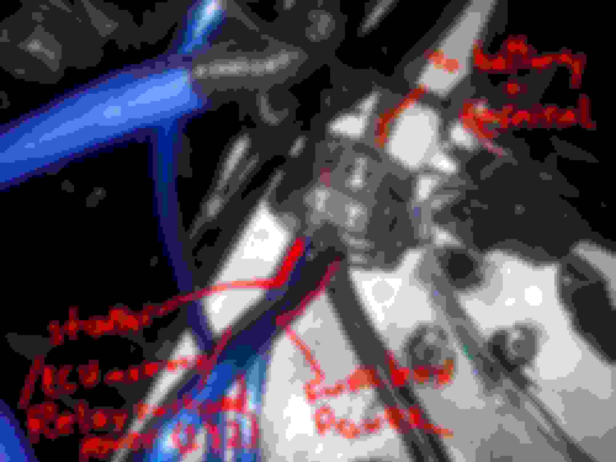
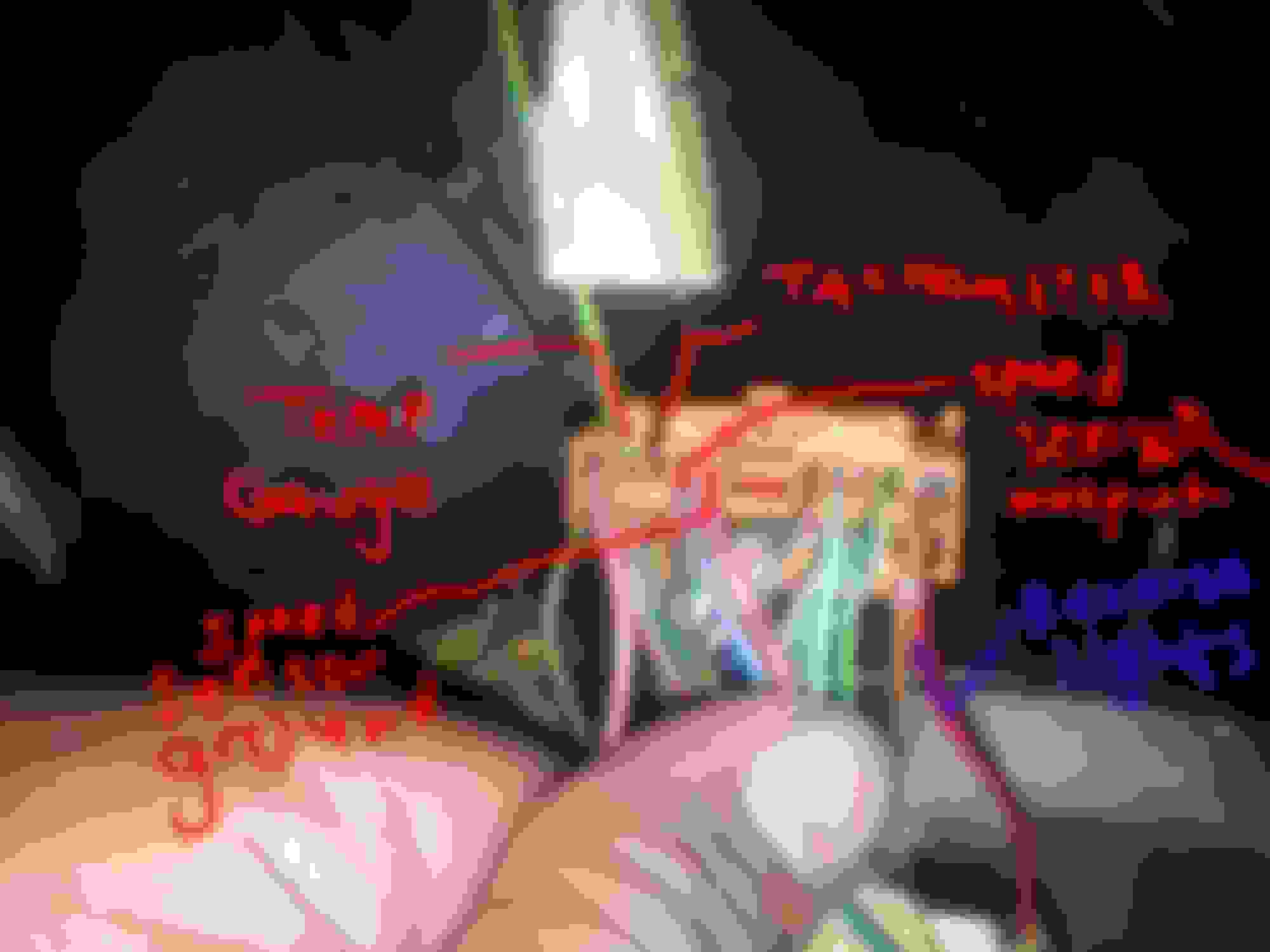
UPDATE: to get the tachometer working in 1997 cars, you need to jump resistor R2 on the back of the gauge cluster, directly above the orange plug. for 92-96 cars, it will be either resister R109 or R73. picture of R2 is right here on my 97 cluster. works for SC300 CLUSTERS ONLY! SC400 CLUSTER WILL NOT WORK WITH THIS MODIFICATION
to get reverse lights working. splice this red wire to your reverse light pin on the orange body plug.
for the AC, cut the squre 4 pin plug off the stock GE harness, only 3 pins are actually wired into it. connect pin1 (top left if you are looking at the plug with the wires coming out the back) to the 8 pin fuse box plug (pin 7) AND pin 1 on the 12 pin white sc300 body plug.
pin 2 on the compressor plug goes to pin 4 on the white 12 pin sc300 body plug
pin 4 on the compressor goes to 8pin fuse box plug (pin1) thats for the magnetic clutch
my 97 sc
two 40 amp fuses with fuel pump wire attached
plug 10897 with pins 2 and 7 used as relays 1 and 2's trigger
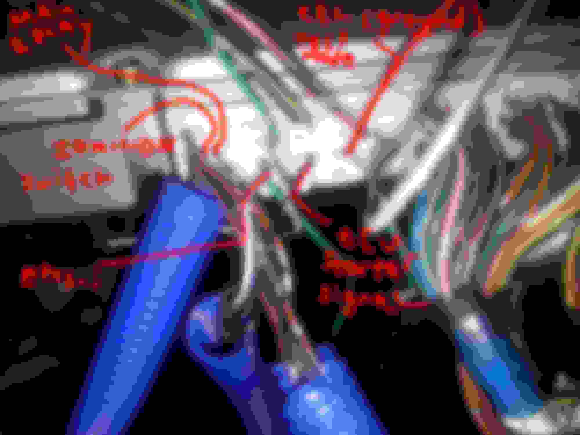
f59 and f60
f60
coils and injectors
battery relocation labeled
power to starter cable, relays 1&2, ecu memory (BATT) pin 1 F60
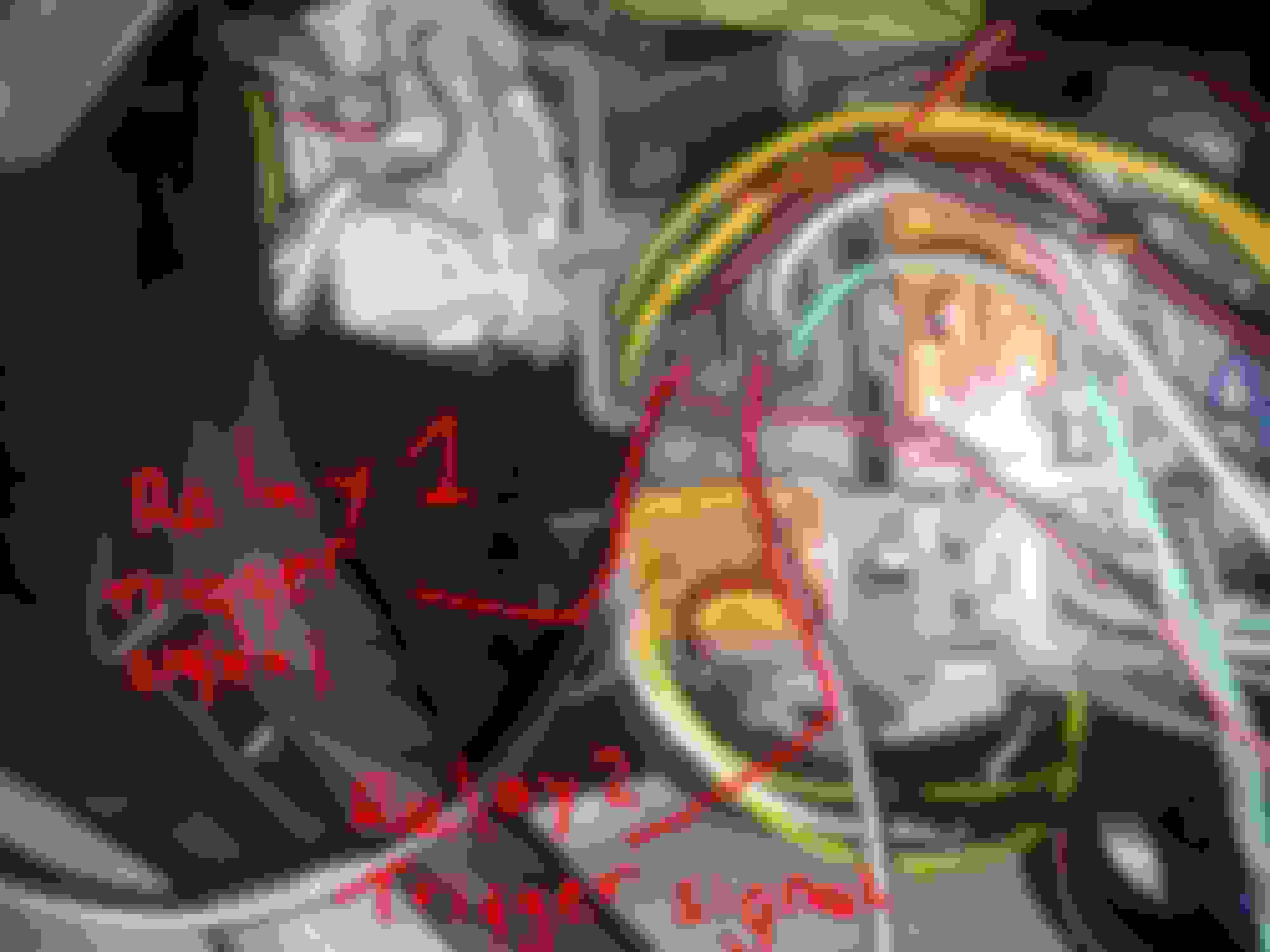
relay diagram
etcs-i wired to EFI circuit (replace 30 amp with 15amp fuse)
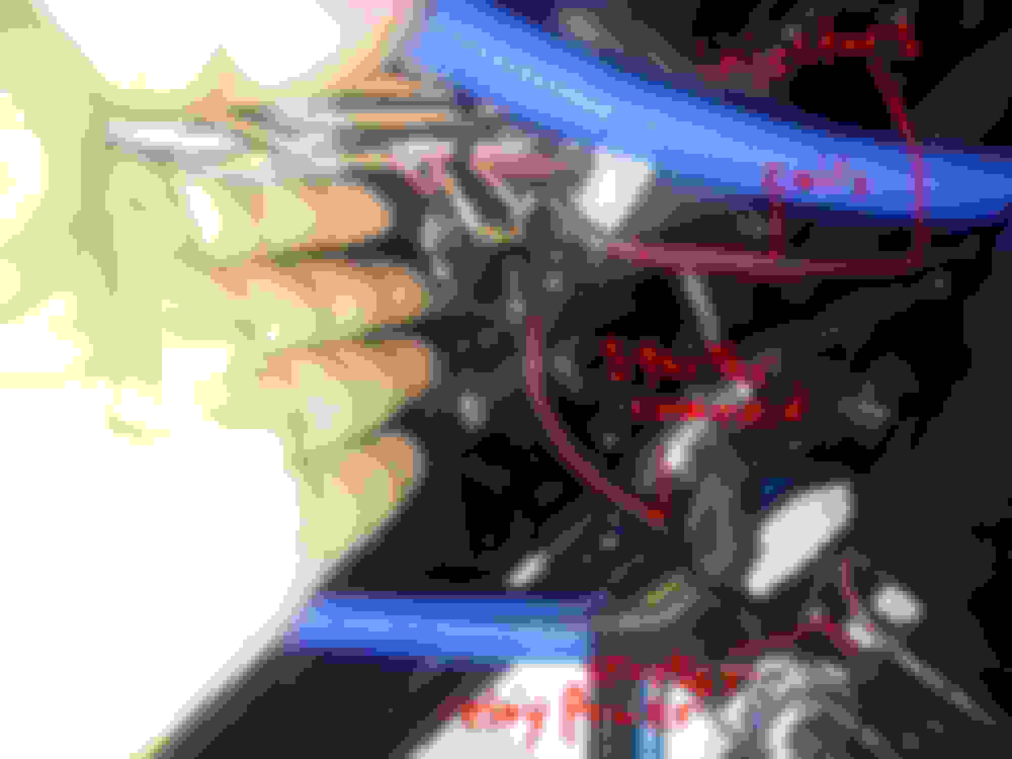
dash and cluster functions through this orange plug
TAC pin usually capped off, but uncap and run a wire to it. should serve as your tach signal
starter solenoid power
starter relay trigger to ECU STA pin and 12 volt crank signal
Last edited by cartzar; 05-28-16 at 10:53 AM.
Reason: adding an update
I have completed the mechanical part of the aristo swap into my 93. I have been trying to use the "wiring made easy" post, and it is driving me nuts. I have been reading it for a week, and my head hurts. I did not extend my harness. This route looks much easier, assuming it will work on the 93. Any thoughts.
^ no, Vvti and non Vvti are completely different. And honestly, there is much nicer ways of going about this current setup. It's not hard to make these look stock and unobtrusive, just takes more effort than what was done here. Not knocking it. If it works, cool. I just like stock stuff to look stock. And before anyone argues that last point, yes, IT IS A STOCK engine. Just because the engine didn't come in this chassis does NOT mean you can't apply and achieve an oem look. I've done GTE swaps in z/x/a chassis that you could not tell wasn't stock, and a 2rz into early 90s pickup to replace the 22r that the Firestone technician who charged the a/c for my customer didn't even know was swapped. It's all about the details, you either care, or you don't.
I have completed the mechanical part of the aristo swap into my 93. I have been trying to use the "wiring made easy" post, and it is driving me nuts. I have been reading it for a week, and my head hurts. I did not extend my harness. This route looks much easier, assuming it will work on the 93. Any thoughts.
it should work fine in a 93 aristo, there is a memeber called Kevin Shockey who has also done the same swap in his 1st gen GS300, and he has gotten it to work fine as well. as long as you use the proper fuses to go inline with all the connections, you should be good to go. look to wilbo666's diagrams to see which connections need which inline fueses installed
Actually, I take that back. After reading like the first few paragraphs and stopping there, I would advise anyone thinking about following this to
A: learn about what is needing to be done on their own and disregarding this
B: pay someone that knows what they're doing such as Mark Panic at panicwire.
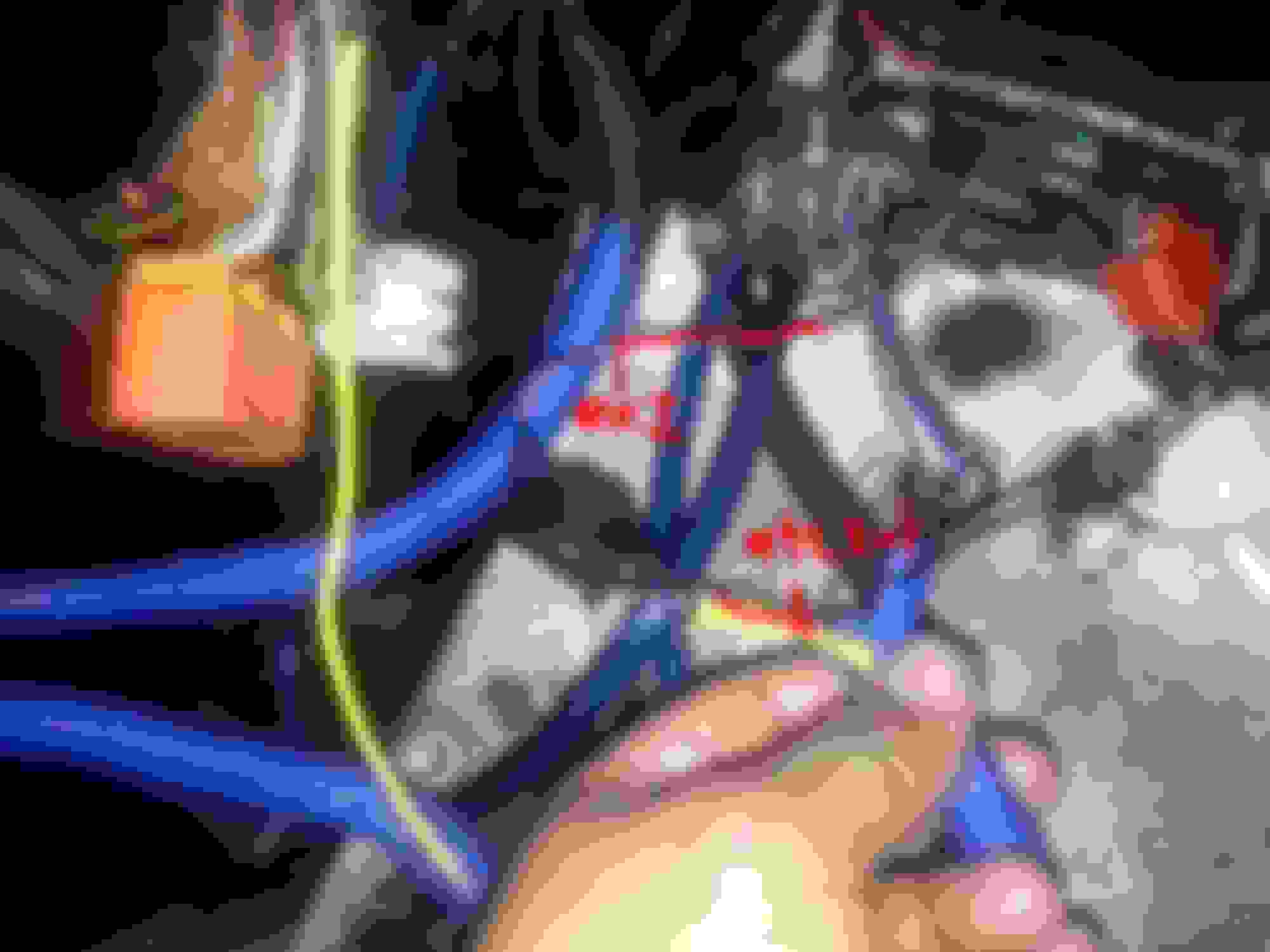
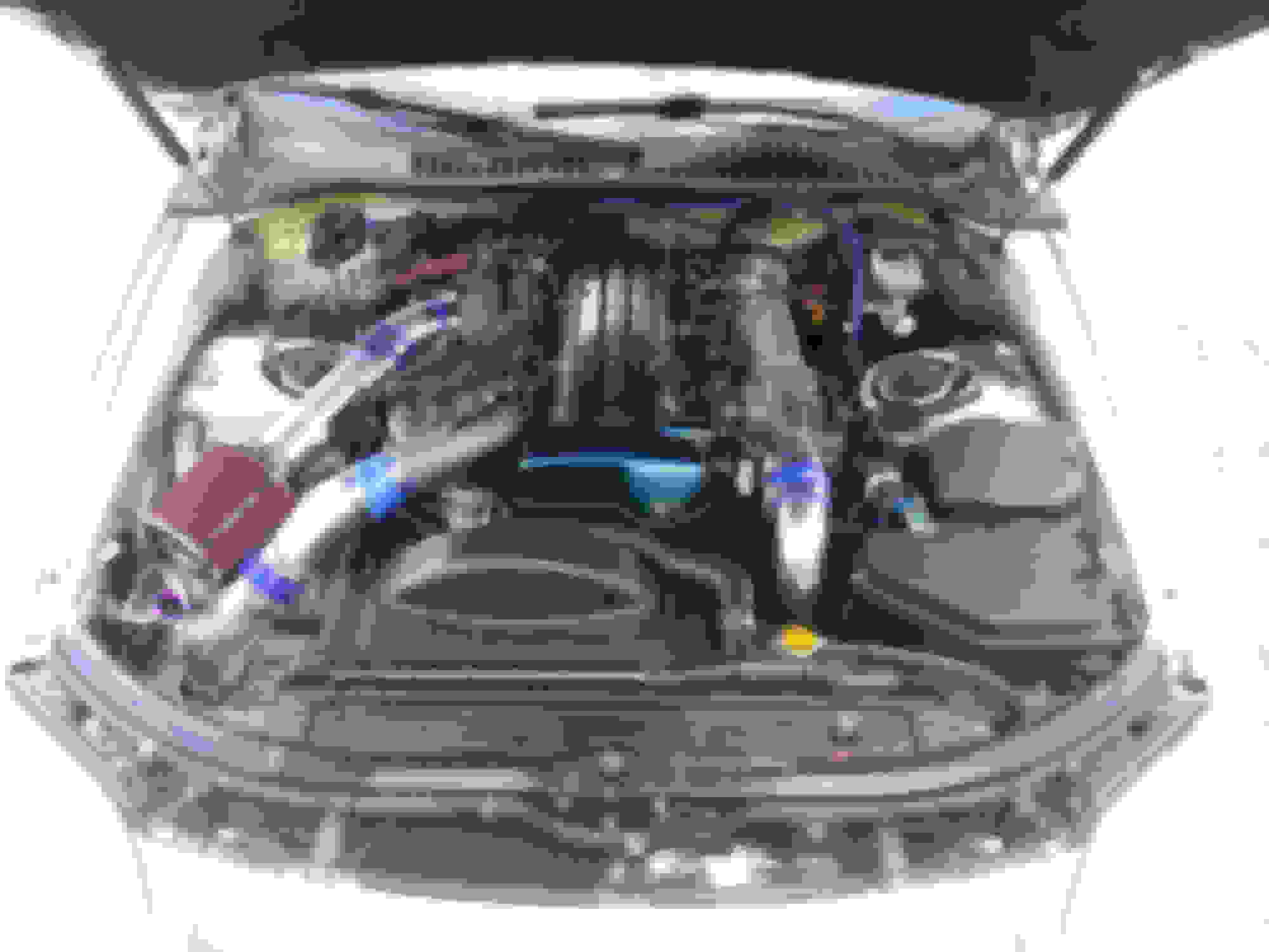
this is what my engine bay looks like. i do care to make it look stock, but i just dont know how to go about doing it. i already paid someone to do it, but that didnt go so well, so i have to figure a lot out on my own
my engine bay. i know its not all that clean, but its to the best of my ability
Actually, I take that back. After reading like the first few paragraphs and stopping there, I would advise anyone thinking about following this to
A: learn about what is needing to be done on their own and disregarding this
B: pay someone that knows what they're doing such as Mark Panic at panicwire.
You're probably right. But because of the situation I was put in, I had to figure out how to wire it myself. If anyone has the resources to do it, they should go right ahead and disregard this and get it done professionally. This is only as a means to get it running if need be
Perhaps I should have been more clear. I have swapped the Aristo gte into my 93 sc300. It is not a GS. Unlike cartzar, my ECM is in the stock location. Instead of extending the harness, I cut a hole in my trans tunnel. I am sure some would say I have butchered my car, but the harness is more than long enough for this approach, and it is the approach I have taken. No looking back now.
Cartzar, your engine bay looks fine. Almost no one outside the Supra community thinks the stock 2jz gte is very pretty anyway, until you remove the twins. It's beauty is in the engineering. This is going to be my daily driver, and when I want to see a beautiful engine, I look at the 6m in my mk1 supra. It's not that fast, but man that engine looks nice.
Cartzar, your engine bay looks fine. Almost no one outside the Supra community thinks the stock 2jz gte is very pretty anyway, until you remove the twins. It's beauty is in the engineering. This is going to be my daily driver, and when I want to see a beautiful engine, I look at the 6m in my mk1 supra. It's not that fast, but man that engine looks nice.
thanks i appreciate it! but your swap should work just fine in your 93 sc, because as long as the engine sees its necessary inputs from the ecu and the vehicle analog electrics, itll do just fine. the stock ecu just needs to see normal electrical conditions, so with proper inline fuses installed in every circuit you should be able to get your swap running fine. if you can, can you please post a picture of your setup and your ecm location? i would love to see how you went about tucking it away
I am at work, but I suppose I will take a picture tomorrow. Not much to see though. The ECM is bolted down in the stock position. The only thing odd is the rectangular hole where the harness comes through the transmission tunnel.
 07-19-15, 09:47 PM