When you click on links to various merchants on this site and make a purchase, this can result in this site earning a commission. Affiliate programs and affiliations include, but are not limited to, the eBay Partner Network.
Tried to start it, its 41 out haha. Your suggested method resulted in nothing, no bang pops or anything, the old method of below i put back in and i got a 450 rpm run for a second then it wouldnt do anything again. I sent in my map and log to ecumasters asking them what my phasing and coil order should be just to confirm as this is crazy.
This is basically the only configuration that has almost started the car:
Also one thing to note that i found recently, not sure why this would occur but my injector plugs read voltage between the two pins meaning the trigger pin has an active ground with just key on. Not sure if this is having an effect on anything as i can validate testing the injectors fine.
Hi Ali! I sent you a PM, realized you probably get hundreds daily, then made a thread, then found this. I'll copy paste my thread, I hope you get around to seeing mine!
I have an SC300 2JZ-GE non-VVT-i. I am deleting the distributor and going with twin turbo coil packs and a plug n play AEM V2 ECU and FFIM. My question is, can I use my stock SC300 igniter with the 6 coil packs through the AEM V2? or do I have to use a GTE igniter? I have read Ali SC's twin turbo coil pack thread, but based on the thread it seems like you only have to swap in a GTE igniter when using the GTE ecu.
Silent, all of that is very odd to me. I am not sure I can help you much more with that ecu setup from here then.
Mike, you need a gte ignitor to run gte coils, even with the aem v2 standalone.
the stock na ignitor will not run more than one coil.
I would recommend using the vvti coils and ignitor, if you don't install the front facing intake manifold (FFIM) the gte coils will not fit under the stock intake crossover but the vvti will.
the vvti is also less wiring, easier to find/replace when the time comes, and more reliable. the gte coils may arguably spark a little better being individual coils vs 3 waste spark vvti coils, but for most setups the vvti works great.
I just wanted to stop in and say thanks again for the enjoyable season I had as a direct result of this and the TT ECU swap. I ended up getting a late start to my driving season due to the gremlins with leaky capacitor issues and then the harmonic balancer separating almost directly after that, but I still put a few thousand miles on the car in 4 months. Took it off the road last night and got the first rain/snow mix last night, and another few inches of snow in the forecast next week...Just in the nick of time. AR-5 swap is incoming over the course of this winter, then I should be able to bump up to 14psi in the spring and see what she's capable of. May even make my first appearance at a dyno to see where it's at.
Thank you for the quick response!! Looks like i'll be going with the VVT-i igniter and coils. Just a couple more questions for you if you don't mind, Where the IGF is on the old igniter, is that black line coming off IGF (where B58 meets IGF in the pic) supposed to be a new connection to the ECU? And are there any changes to this diagram with an AEM V2 plug n play unit? (30-6101)
Those diagrams are a little misleading because on the aem v1 pins 52 and 57 are internally connected (for T1), 53 and 56 are internally connected (for T2), and 53 and 54 are internally connected (for T3).
That is cause the v1 uses waste spark because it does not have 6 individual coil drivers (normally).
So, stock on your 2jzge harness... IGF is already on B58, and coil 1 is already on B57, so you would just be adding T2 to B56 and T3 to B55 and setting it up in the software.
The v2 can support 6 coils, and it can support the 3 coils in wastespark so just need to look up the PDF for that aem v2 version (supra) and it will tell you which pins is which coil # in their software.
I am not sure what the default is on the aem v2, if it is the other way around and wants you to use pins 52-54 for t1-3 instead of pins 55-57, then you move the one pin and add the other 2.
IGF always stays on B58, but the AEM doens't use IGF so you don't even have to worry about that wire but you can move it over to the new ignitor cause its there so why not right?
see this post from the tt ecu mod where I describe how to install the vvti ignitor on a 2jzge harness. the only thing that might change as I said is whether you use 52-54 or 55-57.
I am pretty sure with the v2 you can use either set, but you have to put the numbers in the right boxes in the software then.
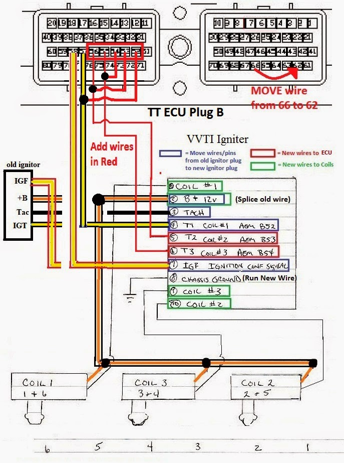
In this next diagram you don't have to do all the wires in red (only need to do that for OEM GTE ecu), just one set as I mentioned above and like your other diagram, but you can see how 1-6, 2-5, and 3-4 are paired off.
This shows how you wire up the coils and also move the wire for the old maf sensor to the new MAP sensor spot (ODB1 only).
Remember the 3 coils have to go in a certain order as shown in the picture (this is the least confusing arrangement trust me): Coil 1 sits on cylinder 6 (and has a lead wire running to cylinder 1 not shown) Coil 3 sits on cylinder 4 (and has a lead wire running to cylinder 3 not shown) Coil 2 sits on cylinder 2 (and has a lead wire running to cylinder 5 not shown)
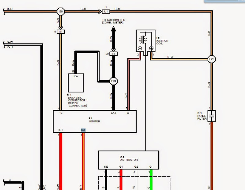
general guideline of what to do for the ignitor wiring: your wire colors may be different but the pin locations are always the same on these ignitors. look at this diagram from a 95 supra for pin locations (I don't have the SC one right now). the power wire is usually black/orange, and the IGF is usually red/yellow... the tach wire is usually black or black white.. the rest well the vary from year to year
First remove all the pins/wires out from the old ignitor plug, and then insert them into the new ds62 ignitor plug as shown in the diagram, this includes +B, tach, IGT1, IGF. you only run 2 new wires from the ecu and that is IGT2 and IGT3. Then you add a ground wire and ground it to chassis ground or even battery ground. For the 4 wires to the coils, you run the 3 signal wires (coils 1-3) to the new coils, and for the +B for the coil you have to splice off the +B wire you just moved over from the old ignitor.
The old coil wire that goes from the stock ignitor to the stock coil is not shown in the diagram above because normally its not used as it goes to the wrong place, but its the 5th wire connected to the old ignitor that's not the 4 shown above. If you were to rewire your harness you could potentially move and reuse this wire, but its easier to just forget about it, and get a mk3 coilpack harness and extend those 4 wires from the coils to the ignitor, as it already has the right clips on it and everything, its just short some.
MONTHS of work to finally figure out i did the timing belt incorrectly. She starts and idles no problem now! I used the dots initially instead of the dashes, i swapped that and threw it back together and she actually runs pretty well!
The way i found this was i compression tested and only yielded about 60 psi on all cyl's, talked to a friend who told me im using the wrong cam markings, loosen the tensioner, pop the belt off correct cam position, bolt it all back together and it fired right up! I had over 150+ psi once corrected.
I'm using G2 for camsync and my firing order is offset by 1.
Today 06:38 AM
As title says. I have a 97 sc3 na-t setup. Usdm tt 6spd ecu maf delete with a map ecu 2, a 2jzgte igniter and
1zz coils( wired to tt ecu mod. Things that I have checked over meticulously. I have fuel getting to the fuel rail ( PHR 8an rail) ID 1000 high z injectors, and a FAST billet FPR. Fuel pump ( walbro 485 e85) has juice and doesnt cut off when turning engine over. Wiring from the coils to ecu have been rechecked. Engine timing is dead on cause when I parked car for turbo kit install car was daily driven and nothing was touched on the timing. Cam gear marks line up on back of timing plate and crank sits at 0 degree. Iat sensor is wired in ( welded on intercooler piping close to TB) resistor mod was done on harness for iat readings on maf connector wiring. Map sensor has voltage. Checked for spark with coil out and I see spark. But I dont see spark on coil 3 and 4. Bought another igniter to test. Same problem. Now, if I spray starter fluid in my FFIM and turn car over it will actually start and idle a bit rough for like 5 or so seconds puffing small clouds of black (fuel) clouds and dies. So that's telling me that their is a cam/crank signal and their is spark. Could I be facing a fuel problem? bad injector or injectors situation? Im not sure if im getting a proper IGF signal. I tested from ecu to igniter and I got 0 results on a voltage. Also if the ecu doesnt respond to the igf signal it will not let the injectors fire, am I correct? So I pulled out my supra usdm tt ecu and igniter and I'm willing to lend it to someone running stock sensors to see if my ecu it's my culprit. I'm trying to think of anything else but everything else seems to be good. Fuses, relays etc. Ive installed all parts myself and car was bone stock prior to my build. Please shine some light upon me...
Silent, that is good news! at least it was something easy but that is a new one lol, the notches are super visible!!
Nuturf87, I don't understand what made you think you can run 1000cc on the tt ecu mod, especially ID 1000cc which are EV14 injectors and newer tech (so injector lag times are different than the original injectors for this ecu which are more like EV1).
even from the US ecu with 550cc, that is doubling it... which might have worked on E85 but on pump gas that is asking alot.
Also the usdm being a maf setup, its not going to scale as well as the jdm ecu from a piggyback, meaning its hard enough to get the USDM ecu to work on na-t with the stock 550cc injectors.
So in summary, I doubt it will start and run properly with ID1000 cc injectors, you might get it to start and idle to some degree but it won't be pretty when you tap the gas.
if its running for 5 seconds then it should do the same wihtout the starter fluid regardless of IGF there or not. for the 1zz coils you just connect all 6 IGF wires together to the stock IGF wire.
Get yourself some 550cc injectors of the old school variety that are top feed high impedance and work from there.
Or if you don't have to deal with emissions, just swap to a JDM ecu but still anything over 550cc or even 600cc on the jdm ecu will start to have problems.
on USDM ecu I wouldn't push more than stock 550's cause of the maf setup.
Basically get 550cc injectors and you can still do tweaks with the map ecu, but do note setting up the map ecu can be tricky, I have had no starts on the base maps lots of times without tweaking.
Also if you have an actual IAT in the loop, you should not put a resistor in place of the IAT on the maf connector, you do one or the other, not both. that could be part of your issue.
hope that sheds some light, good luck.
Haha leave it to me to mess up literally the easiest part of the build. I 100% understand the JZ now rofl. Wish i would have found it sooner so i could have got some racing in 2019! oh well she'll come out strong 2020.
Thanks for the endless help! I'll keep my build post updated as i go on.
If you notice there is a big dot further down on one side of the cam gear, that should line up with the notch which is TDC (and not the small dot you used).
I think that small dot is a "service position" for the timing belt procedure. I never use the extra markings since everything I have assembled was non interference still.
Yep i noticed the large dot on one of the "spokes" of the cam gear and i was looking at the manual and was like crap i messed up haha.
It wouldn't be my build if i didnt struggle to start it for a month or two. (its happened before on my old trans am build haha)
 11-01-19, 08:31 AM