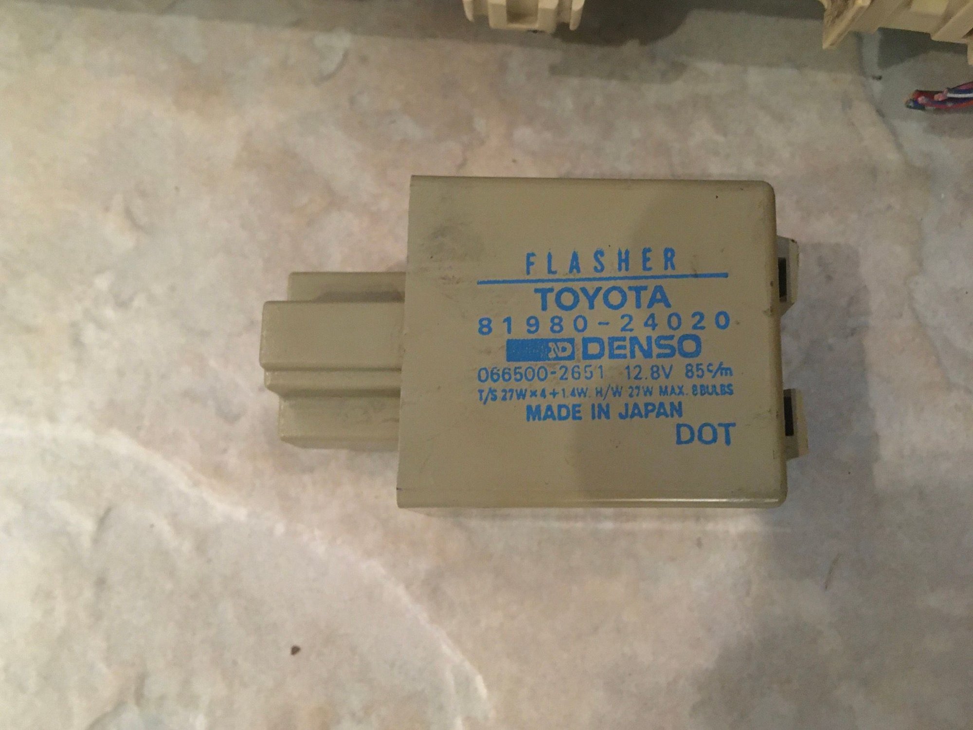
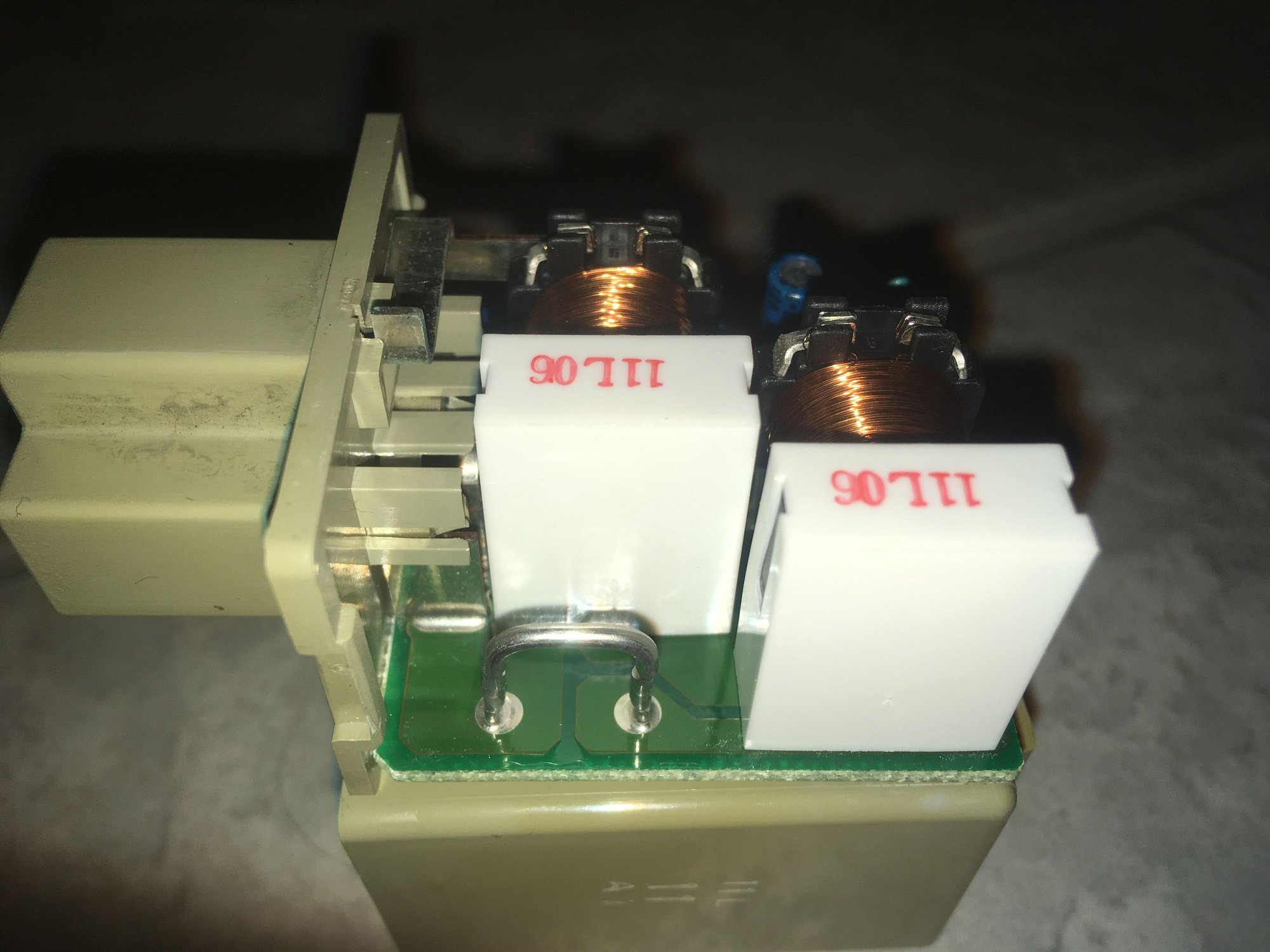
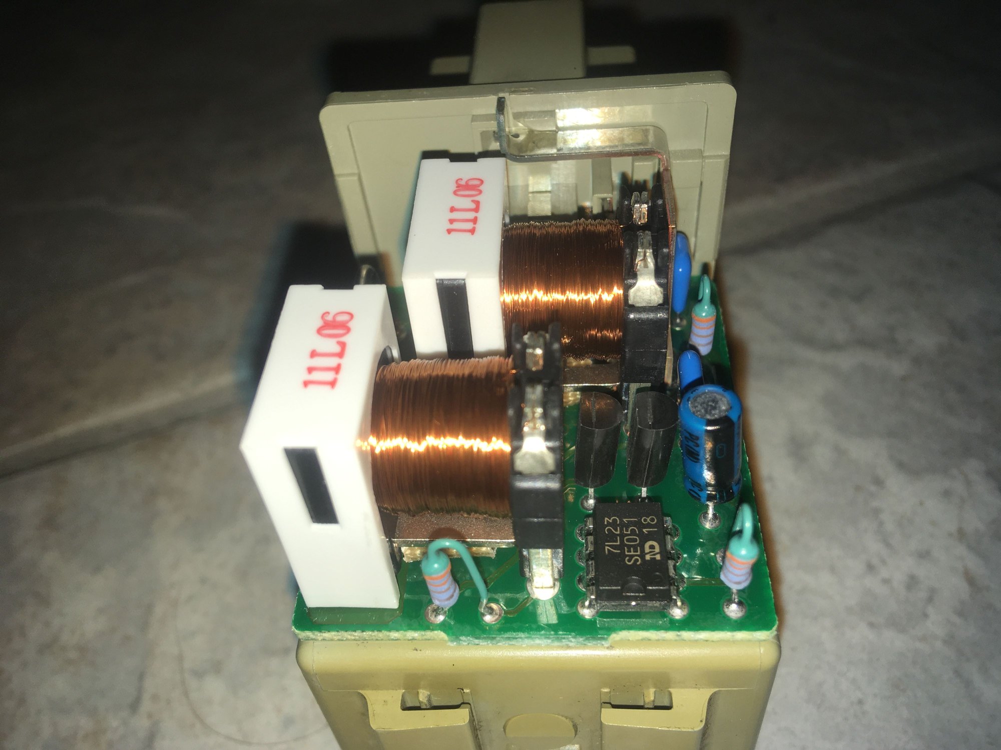
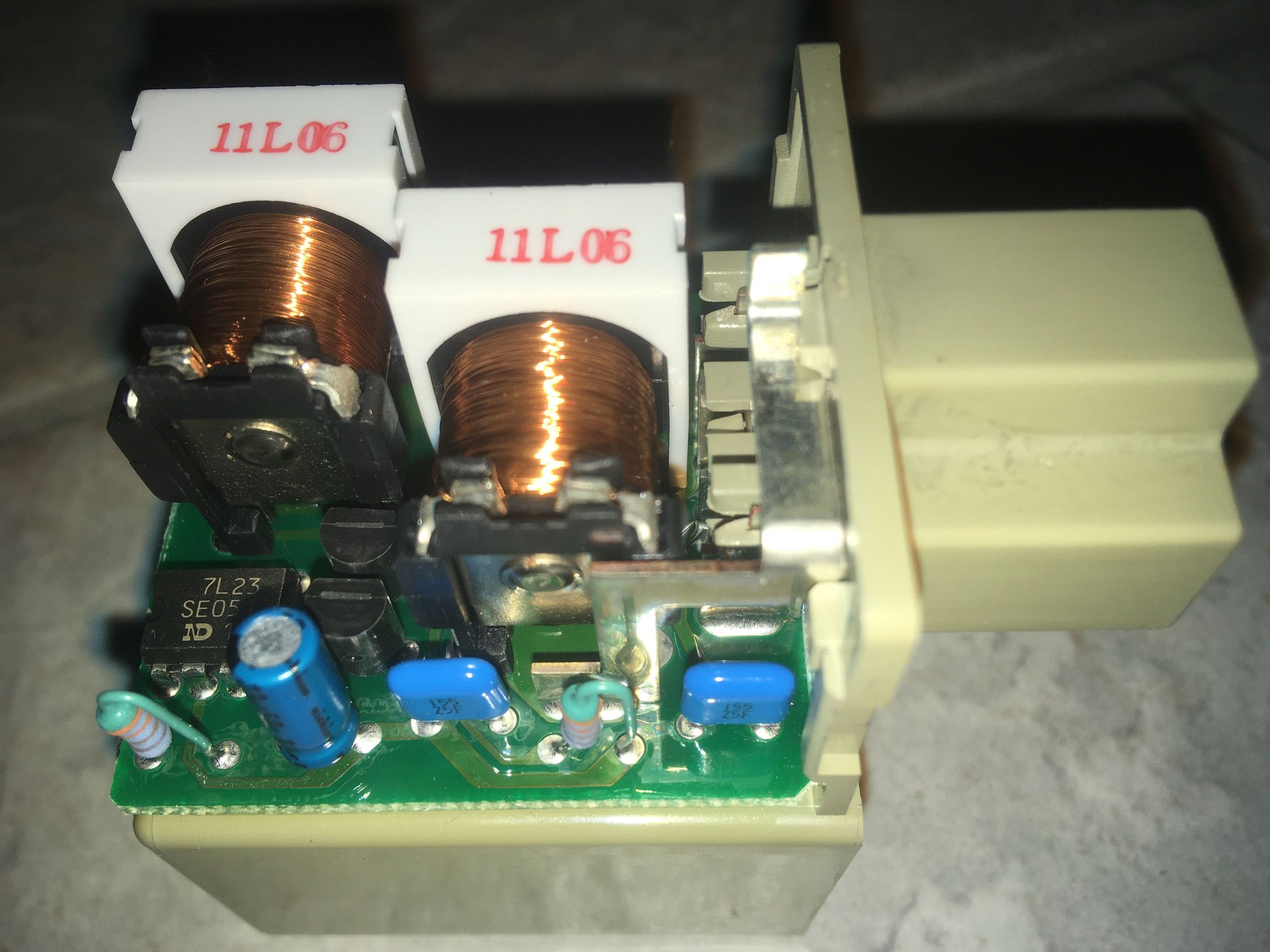
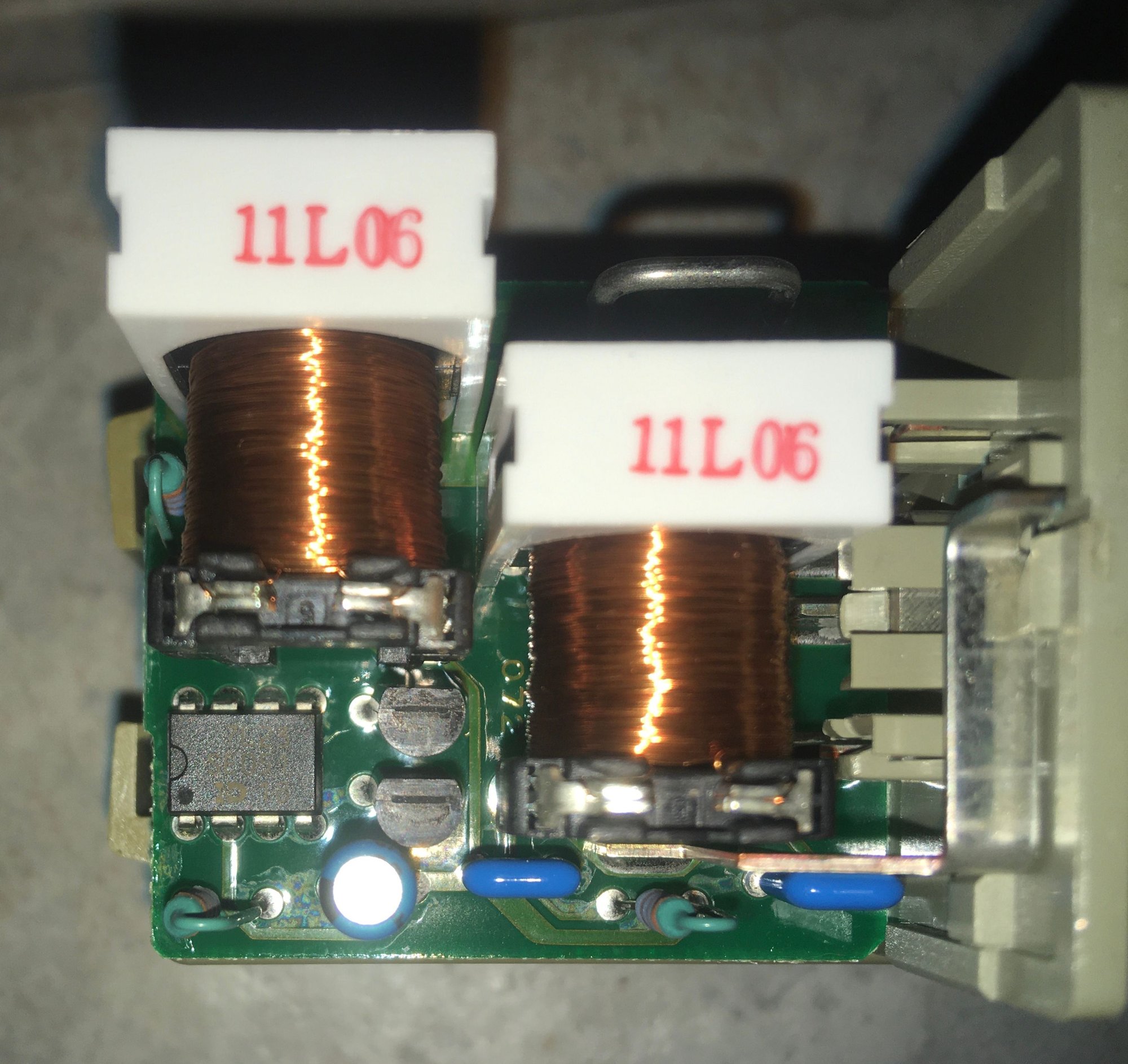
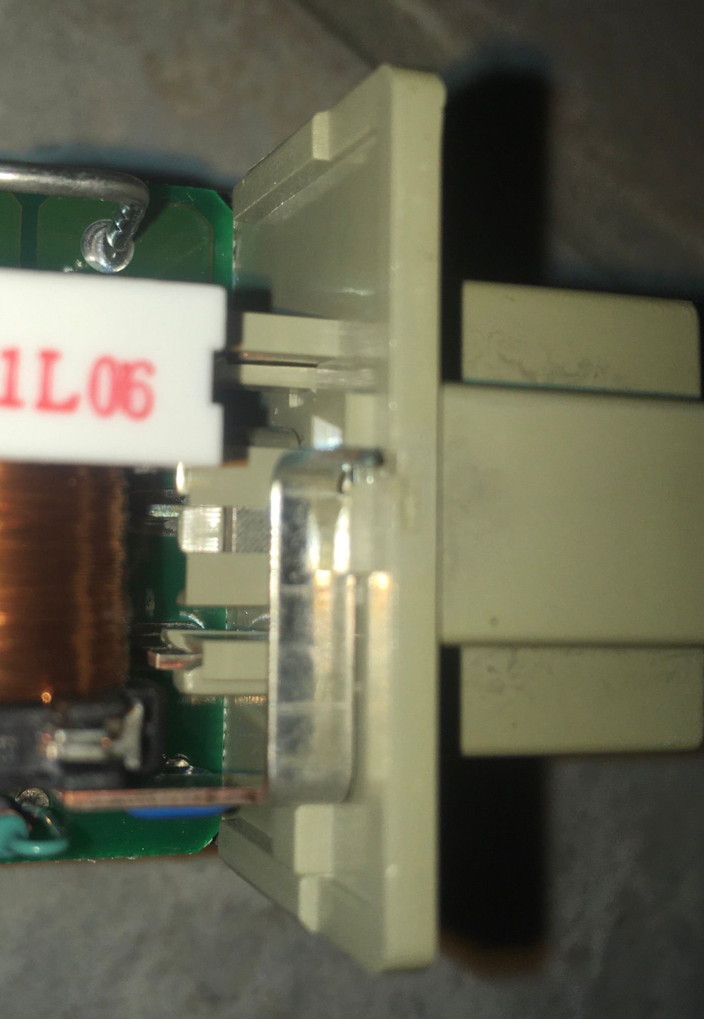
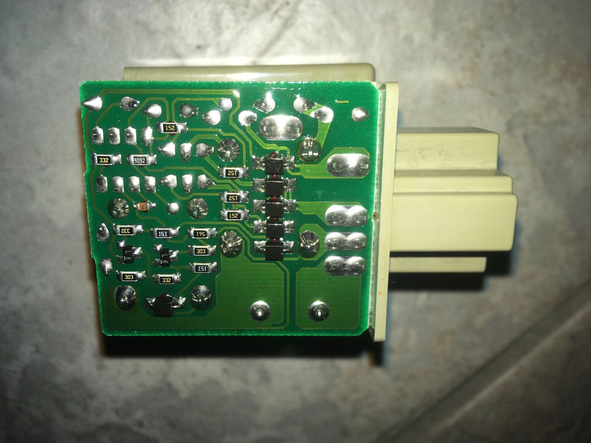
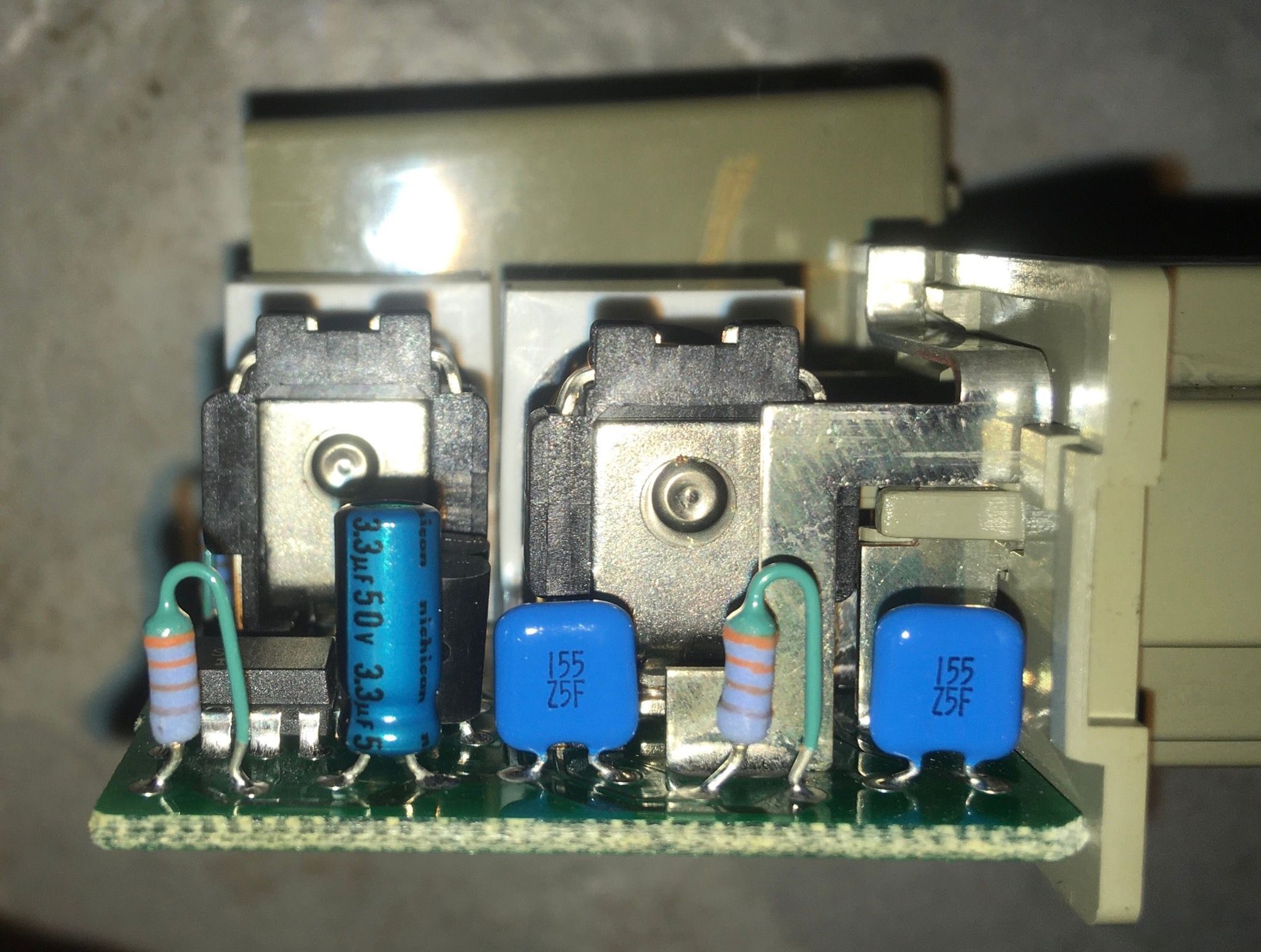
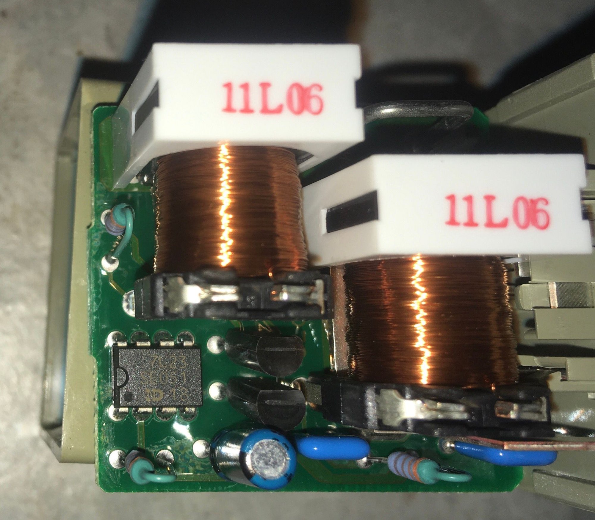
Possibility for rebuilding or remaking 92-94 SC300/400 Flasher Relay 81980-24020
#16
Recently some early SC300/400 owners with model years 1992-1994 (except very late-1994) have reported some issues with their factory turn signal relays. It turns out that this relay (Toyota/Lexus P/N 81980-24020) and its 1991-1994 Soarer variant (Toyota Japan P/N 81980-24010) are both discontinued. These respective relays were also only made for the early SC and early Z30 Soarer model years. Given that Toyota produces parts for their cars for anywhere between 15-20 years (or more in some cases where a part cross references to many other models) this extremely model specific relay may have stopped being produced around 2014 or so. They last so long it probably took until just recently for the worldwide stock to run out.
That being said, they're very well made and long lasting but given the age of these cars now a replacement might be needed and the only options are currently used. For a turn signal relay.
It is a very oddball design. It uses a standard Bosch 5-Pin relay pin arrangement but the actual function and assignment of each pin is completely different. Also, it houses not one but TWO relay mechanisms inside it which according to Yamae actually splits the electrical load for the Left signal over one of them and the Right signal over the other one. And for timing control it uses several capacitors and a small digital timing chip among its other components.
Aftermarket relays available supposedly for the 1992-1994 SC's will NOT work as they are not 5-pin. And even if a common 5-pin aftermarket relay were to be plugged in it also would not work as it is not at all configured in the right way. On the other hand 1995-2000 SC300/400/Soarers CAN use a more commonly available and simpler OEM Toyota flasher relay or common aftermarket types. But not 92-94 SC's or 91-94 Soarers.
This thread is an attempt to find a way to rebuild these if they have become non-functional or defective and also to investigate the possibility of custom building an aftermarket twin-internal-relay alternative that uses the same 5-pin socket layout and pin assignment as the original factory relay.
Hopefully in this thread we can dissect the original relay's workings, ascertain how it works, identify its components and attempt to source new internal electronics from either high grade aftermarket suppliers of small electronics (such as very specific type capacitors, etc.) and even from more common OEM Toyota/Denso relays that might also use some of the same parts.
Hopefully a solution or two can be hit upon to allow 1992-1994 SC and 1991-1994 Soarer owners to not have to worry about not being able to find new factory turn signal relay replacements for their cars which would be an incredibly simple and common fix for almost any other vehicle.
Last edited by KahnBB6; 08-16-20 at 02:00 AM.
#18
Moderator

Yamae! Thank you, thank you, thank you!!! My apologies for the belated reply. It was an intense day and I couldn't get back to the thread to respond and consider the new information before now. I was in no way pushing you to dig deeper to go to such lengths as contacting other Toyota engineer friends but this is amazing! We're in your debt!!
Based on what your colleagues told you about the 5-pin, twin internal relay design is very interesting. So this was a means of reducing wear over time on the electrical contacts for premium Toyota models. I'd venture a guess that today with almost everything being LED based these current draw concerns would not require such a beefed up electrical design but in 1990 or so this must have been the way to make a signal flasher relay and circuit on a premium car last a VERY long time. Even though it presents a difficult situation at the moment I'm impressed with this idea that was used on some Toyotas from the Z20 through the Z30 eras.
I looked through all of my TSRM schematics for the SC300/400 again but had no luck finding any internal diagram of the twin-unit flasher relay such as you have found for the Z20 Soarer.
I did find this simplified diagram the day before yesterday but it was already posted above as an attachment. I'll put it in this post anyway just for reference:
^^ But as you can see, neither in this simplified SC300/400 Turn Signal schematic or the more detailed black-and-white schematic of the same circuit in the previous post above has any detail of how the internals of the 5-pin flasher relay actually works.
From your Z20 5-pin flasher diagram we can see the logic at work that the engineers wanted us to understand even if there are no schematics of the inside of it. So that along with the pinout that we have for the North American SC (and by extension I assume the JDM Z30 Soarer) should tell us what function needs to get assigned to which pin and how the twin relays need to be wired to individually handle the Left and Right signals and Hazard Flash functions.
But I think this brings us to the digital chip inside this relay. I think that is what needs to be wired to from the five contact pins on the outside of the relay and from the chip we would need to wire the relay pins themselves. That leaves the question of which pin does what on the digital controller chip?
For that, I think we will need a donor SC flasher relay to inspect carefully especially where this chip is. I have located a used one yesterday which I should be receiving in the mail soon. I will take many high resolution closeup pictures of its internal configuration and attempt to map the circuit board, the digital controller chip pins and which other components they connect to.
As a bonus, I have a spare 1992 SC driver's side fuse block footwell kick panel coming in complete with the "integration relay" that is housed on the back of it. This will provide a way to test at least the fitment of the relay and perhaps even some electrical connections to the flasher relay. Hopefully.
Now... I am somewhat familiar with working on small electronics and I am comfortable working on automotive electrical wiring and looking at electrical circuit reference diagrams to sort out issues or rewire an engine harness... but some aspects of basic electronics design and what some terms mean are still new to me.
When you say "flushing speed"... can you explain what this means? Is this to do with the speed at which the 12V-to-0V-to-12V switching sequence of the relay can occur?
I am still thinking in terms of Option A being to repair the factory relay unit in some way and Option B being the custom/aftermarket twin aftermarket relay solution you suggest is possible. And honestly I think you're right-- there probably is a way to do this with two simple 3-pin aftermarket relays once we can figure out how to control them and time them (with capacitors I assume).
When I have the spare SC flasher relay in hand after it arrives I will open it up and look. I am thinking... other than some fine tuning with different electrolytic capacitors and the wattage-sensing circuit also included.... the way to control two aftermarket relays may come back to the way Toyota officially did this: by routing the five pin functions through a digital controller microchip which then doles out the switching logic and decisions to each of the two relays. And I am willing to bet that the two OEM internal relays are of a very simple design... maybe only three pins each (internally x2).
And if pictures of the OEM relay internals prove this to be correct then it will line up right along with your custom aftermarket idea to use two simple aftermarket 3-pin relays once we can figure out a way to control them.
Another thing is that once I have the spare fuse kick panel to set up on my workbench I can confirm whether or not a standard Bosch-style 5-pin relay can physically connect into that space. Then... even though we would need to modify it internally and gut it basically this might serve as a basis to completely rewire the internal side of the aftermarket 5-pin relay with your idea. Maybe at that point a 3D printed casing would be needed... or maybe the original flasher relay casing would be needed.
At the same time I also want to catalog and identify each electronic part inside the OEM relay in case new components can be sourced.
I am thinking out loud and brainstorming. Perhaps I am getting ahead FAR of myself, lol. I feel like I'm throwing in every piece of information I can think of at the moment.
I am going to sleep on this and give it some more thought but as before I am very curious as to what you may think about this so far and if any of the above ideas seem to you closer to the mark or farther off the mark to a good and reliable solution.
It will take a few days until I will receive the spare flasher relay in the mail. Once I get it I will start taking detailed pictures of the inside and posting them here.
Again, Yamae, thank you very much for helping to looking into this with us and sharing your expertise and experience!
I am not familiar to flasher relays and I just needed to ask my friends about those. According to them, there are many variations. The most simple and old relays are only consisting of a coil with a magnet and contacts. No semiconductors, C nor R are used. The driving coil is series with bulbs and flashing cycle is decided by the current of the coil. When one of bulbs is open, the current will be automatically decreased and the flashing speed will be changed to faster due to the less driving energy which can not hold the contacts to close/make long enough. Newer relays with semiconductors with C&R do not have a coil as previous ones but to let the driver to notice, the flashing cycle has to be changed faster when one of bulbs is open. Thus a current sensing resistor is used to perform this.
The "flushing cycle" I mean here is the same with the "flushing speed". It is depend on the load. When you use a 3 pin flusher relay instead of a 5 pin relay, the load (number of bulbs) is lighter and the flashing speed becomes faster. At my previous post I wrote, "This is just my guess, when we use 2 relays, the flushing speed becomes slower", this was incorrect. I should have written "faster". Sorry for my mistake.
The following users liked this post:
KahnBB6 (08-18-20)
#19
FYI to anyone with a 1992-1994 SC300/400 (or a 1991-1994 Toyota Soarer Z30) who is in need of repair for a defective 81980-24020 (or Soarer 81980-24010) flasher relay unit that is unique to these early model year cars, FredMahan has found a company that can repair these units at what may prove to be their most common failure points. Thank you Fred!!!
This is Relentless Motorsports LLC in Texas.
https://www.clublexus.com/forums/sc-...l#post10898279
...
In addition I am about to send a spare 81980-24020 flasher relay that I have out to CL member Lexus2000, an electrical engineer, who has agreed to take a look at the unit's design and attempt to determine if a clone or simplified version can be built and still work electrically as the early SC needs it to. One step at a time and we'll see what comes of that.
....
Yamae, at the time you posted this things got very busy on my end and I did not thank you properly for explaining these points further. I really appreciate the insight and your taking the time to go over these to help us better understand the reasoning behind the original design of this relay's function. To be honest when I first read it it went a little over my head and I had to give it some time to come back to review your post again. It is clearer to me now.
Still, much of the actual implementation of a re-design of this twin-relay-within-a-relay unit is beyond my capabilities. And as such, I've tried to seek out minds more learned than I am in electronics design who may be able to work with this knowledge to come up with a better replacement solution.
Fred's recent discovery (above ^^) is a revelation in itself and it may be that small fixes to any defective relay units may be all that is really needed... since they are so very over-engineered. But as they are old hardware and will only get older I think it's still a good idea to at least look into the possibility and feasibility of coming up with an aftermarket replacement relay unit for 1992-1994 SC's and 1991-1994 Soarers that works as it should just like the factory unit.
....
Aside, my other concern is the early SC300/400 (and Soarer's) "Integration Relay" that plugs into the back of the driver's side fuse kick panel. This is actually more of a logic board populated mostly by microchips. I have heard of those going bad occasionally as well and that may prove to be much more difficult to find repairs for.
But for the Integration Relay I would make a new and separate thread for discussion about that.
This is Relentless Motorsports LLC in Texas.
https://www.clublexus.com/forums/sc-...l#post10898279
I have found someone who can repair the 1992-94 81980-24020 Flasher units. He is Josh at relentlessmotorsportsllc.com . He quoted me
$35 to repair mine, but it ended up costing $45 because he had to replace more parts than he expected. Cheap for something that is
unobtainium! He has a 1992 SC300 and tested mine in his car before he sent it back. Works fine in my car now. I sent him my spare for
repairs last week. He said that he found acid on the board, caught it just in time, and cleaned it up, which possibly indicated a leaking
capacitor. The contacts on the coils also may be going bad. Relentless Motorsports also repairs ECU units. He uses Japanese parts
as much as possible. Two thumbs up!
Fred
In addition I am about to send a spare 81980-24020 flasher relay that I have out to CL member Lexus2000, an electrical engineer, who has agreed to take a look at the unit's design and attempt to determine if a clone or simplified version can be built and still work electrically as the early SC needs it to. One step at a time and we'll see what comes of that.
....
You are welcome, KahnBB6. It is my pleasure that my limited investigations are still somehow useful for your next step.
I am not familiar to flasher relays and I just needed to ask my friends about those. According to them, there are many variations. The most simple and old relays are only consisting of a coil with a magnet and contacts. No semiconductors, C nor R are used. The driving coil is series with bulbs and flashing cycle is decided by the current of the coil. When one of bulbs is open, the current will be automatically decreased and the flashing speed will be changed to faster due to the less driving energy which can not hold the contacts to close/make long enough. Newer relays with semiconductors with C&R do not have a coil as previous ones but to let the driver to notice, the flashing cycle has to be changed faster when one of bulbs is open. Thus a current sensing resistor is used to perform this.
The "flushing cycle" I mean here is the same with the "flushing speed". It is depend on the load. When you use a 3 pin flusher relay instead of a 5 pin relay, the load (number of bulbs) is lighter and the flashing speed becomes faster. At my previous post I wrote, "This is just my guess, when we use 2 relays, the flushing speed becomes slower", this was incorrect. I should have written "faster". Sorry for my mistake.
Still, much of the actual implementation of a re-design of this twin-relay-within-a-relay unit is beyond my capabilities. And as such, I've tried to seek out minds more learned than I am in electronics design who may be able to work with this knowledge to come up with a better replacement solution.
Fred's recent discovery (above ^^) is a revelation in itself and it may be that small fixes to any defective relay units may be all that is really needed... since they are so very over-engineered. But as they are old hardware and will only get older I think it's still a good idea to at least look into the possibility and feasibility of coming up with an aftermarket replacement relay unit for 1992-1994 SC's and 1991-1994 Soarers that works as it should just like the factory unit.
....
Aside, my other concern is the early SC300/400 (and Soarer's) "Integration Relay" that plugs into the back of the driver's side fuse kick panel. This is actually more of a logic board populated mostly by microchips. I have heard of those going bad occasionally as well and that may prove to be much more difficult to find repairs for.
But for the Integration Relay I would make a new and separate thread for discussion about that.
Last edited by KahnBB6; 09-23-20 at 01:01 AM.
The following users liked this post:
Bimmerbill (09-24-20)
#20
Lexus Fanatic
Proof of concept test I did using this LED flasher relay
I don't recommend this particular one more on that later.
LED flasher wired in to the original fuse/relay block

This is a 2 relay flasher just like the factory one


Here is the pinouts for this flasher

Ignition and +12VDC I tied together. There is a dedicated pin for activating hazard function this is not used or needed, the factory hazard switch simply activates both sides/relays at once.
Here's a video
https://streamable.com/a3ix6t
Notice when the signal is first activated the lamp stays on longer vs. the rest of the flashes. This is not being done by me that's how the flasher is programmed. I've seen the same problem in other LED flashers, so don't get the one I linked to hopefully others don't have this issue.
I'm using spade connectors plugged into the original connector.

This could work for a permanent solution, make the wires short and remove the connector pins on the LED flasher module. Ideally it would be best to use a connector that mates with the fuse block. Either way this is one solution and the nice thing it gives the ability to go LED without load resistors. Another option (much harder, but best) is strip the original flasher of all components expect the connector leads and solder/integrate the LED flasher into the original housing. Reverse engineering the factory flasher is not worth the time and effort, plus it would be fairly expensive to get a PCB made, and soldering SMD components is time consuming.
I don't know why the factory flashers fail, the one KahnBB6 sent me is working fine I tested it. If I had to guess the SMD transistors burn out.
I don't recommend this particular one more on that later.
LED flasher wired in to the original fuse/relay block

This is a 2 relay flasher just like the factory one


Here is the pinouts for this flasher

Ignition and +12VDC I tied together. There is a dedicated pin for activating hazard function this is not used or needed, the factory hazard switch simply activates both sides/relays at once.
Here's a video
https://streamable.com/a3ix6t
Notice when the signal is first activated the lamp stays on longer vs. the rest of the flashes. This is not being done by me that's how the flasher is programmed. I've seen the same problem in other LED flashers, so don't get the one I linked to hopefully others don't have this issue.
I'm using spade connectors plugged into the original connector.

This could work for a permanent solution, make the wires short and remove the connector pins on the LED flasher module. Ideally it would be best to use a connector that mates with the fuse block. Either way this is one solution and the nice thing it gives the ability to go LED without load resistors. Another option (much harder, but best) is strip the original flasher of all components expect the connector leads and solder/integrate the LED flasher into the original housing. Reverse engineering the factory flasher is not worth the time and effort, plus it would be fairly expensive to get a PCB made, and soldering SMD components is time consuming.
I don't know why the factory flashers fail, the one KahnBB6 sent me is working fine I tested it. If I had to guess the SMD transistors burn out.
The following 2 users liked this post by LeX2K:
GMXSexCy300 (01-05-24),
KahnBB6 (10-22-20)
#21
Lexus Fanatic
The following users liked this post:
KahnBB6 (10-22-20)
#22
Lexus Fanatic
After a bit of research it seems the aftermarket versions of this flasher are all the same, meaning the same flaw. Will try and find the OEM version of this flasher and test.
....looks like the generation 5 Camry uses the appropriate one should be able to find one at the local salvage yards.
....looks like the generation 5 Camry uses the appropriate one should be able to find one at the local salvage yards.
Last edited by LeX2K; 10-22-20 at 02:43 PM.
The following users liked this post:
KahnBB6 (10-24-20)
#23
Lexus Fanatic
Another update, got a hold of a Camry gen5 flasher


Nice thing is there is a separate connector that only goes to the flasher module makes it easy to use. Here are the wire colours/pinouts
red/light blue - ignition +12v
white - +12v
light green/blue - heater switch to ground (goes unused)
green/white - turn output left
green/yellow - turn output right
green/black - turn input left
green/yellow - turn input right
white/black - ground (this will have to be hooked to body ground somewhere under the dash)
So turns out the solution was right under our noses all along just needed to know the compatible cars/signal relay. To make a replacement you need the relay plus connector/wires, solder spade connectors on 5 of them. That's it.
List of donor vehicles, also easy to find 81980-02030 on Ebay.
01/2002-12/2007 TOYOTA COROLLA, MATRIX ZZE13*
07/2001-01/2006 TOYOTA CAMRY ACV30,MCV3*
07/2003-11/2008 TOYOTA SOLARA ACV30,MCV31
01/2005-09/2012 TOYOTA AVALON GSX30
01/2003-11/2009 TOYOTA SIENNA GSL2*,MCL2*
01/2010- TOYOTA SIENNA ASL30,GSL3*
09/2004- TOYOTA TACOMA GRN2**,3**,TRN2**
02/1999-09/2006 TOYOTA TUNDRA GSK30,UCK3*,4*,VCK30,40
Last edited by LeX2K; 10-27-20 at 04:08 PM.
#24
This is excellent news!!! So this Camry Gen5 flasher functions just like our stock flasher relays once the pinouts are accounted for?
Now for any old SC flashers that cannot be re-capped and given new resistors and large transistors to fix their issues we have a real alternative!! Thank you!!
Now, with that connector you used to plug into the Camry flasher module can you read off the 5-digit numbers embossed somewhere on its casing? If we add "90980-" to the front of those five digits we'll have the part number to order it with and match the correct terminal repair wire P/N's to so that we can easily make patch harnesses from them.
The spade connectors into the 92-94 SC's footwell flasher relay receptacle sounds like it *may* be the only good bet but since it's hard to access I'd like to see if there is any way we an re-purpose a standard 5-pin Bosch relay base/spades and tie them all to the pinout wires you've provided.
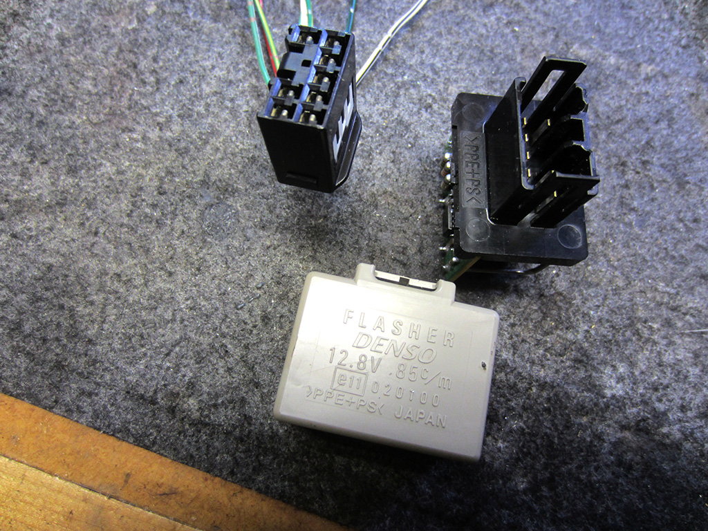
Or... are you saying that the connector shown in your picture comes with the Camry gen5 flasher relay?
#25
Lexus Fanatic
Now for any old SC flashers that cannot be re-capped and given new resistors and large transistors to fix their issues we have a real alternative!! Thank you!!
Now, with that connector you used to plug into the Camry flasher module can you read off the 5-digit numbers embossed somewhere on its casing? If we add "90980-" to the front of those five digits we'll have the part number to order it with and match the correct terminal repair wire P/N's to so that we can easily make patch harnesses from them.
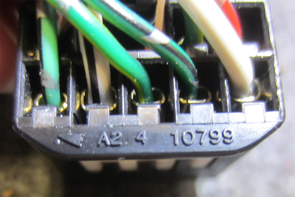
The spade connectors into the 92-94 SC's footwell flasher relay receptacle sounds like it *may* be the only good bet but since it's hard to access I'd like to see if there is any way we an re-purpose a standard 5-pin Bosch relay base/spades and tie them all to the pinout wires you've provided.
Or... are you saying that the connector shown in your picture comes with the Camry gen5 flasher relay?
If a 5-pin Bosch relay has the same pin spacing I can gut that and combine it with the Camry flasher.
For clarity here is the whole deal.
#26
Yes, plus one extra which in the wiring diagram is labelled "heater switch" (not sure why) but it in fact hazard activate. As I said before this wire will go unused since on the SC hazard grounds/activates both sides of the signal at the same time, hence you get hazard lights.
This thread and these findings must be made into a sticky now. I'll get on that. I like the idea of repairing and re-using the factory flasher relay... if possible. But if the most common electrical replacement parts cannot cure someone's issue then you've discovered a novel solution for us!
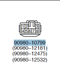
That makes the part number for that connector 90980-10799... which I see as a valid Toyota part number in the ordering system. From that part number, if necessary, we can also identify the replacement terminal wires associated and order only the exact number of wires needed with which to create a patch harness to a 5-Pin Bosch style connector.
Edit/Update: Toyota connector 90980-10799 uses 8x OEM terminal repair wires and the two types listed for it are 82998-12340 and 82998-24380. Either type will probably do for this application.

I agree... if an inexpensive 5-pin Bosch relay base can be identified with which to cannibalize and create the other end of a full patch harness then we'll be in business. Then only an adequate length for the patch harness wires and an easy way to secure the Camry Gen5 relay in that area will be needed to complete this.
It looks good to me! And that flasher relay part number is still good and available from Toyota brand new so this is all very promising!
Last edited by KahnBB6; 09-07-21 at 07:49 PM.
#27
Lexus Fanatic
Does this relay have the proper pin spacing? If so I'll grab one and combine it with the Toyota one.
edit - there are many generic versions available and for cheap so if the pin spacing is good then a low cost solution.
edit - there are many generic versions available and for cheap so if the pin spacing is good then a low cost solution.
Last edited by LeX2K; 11-02-20 at 02:01 PM.
#28
Lexus Fanatic
But if the most common electrical replacement parts cannot cure someone's issue then you've discovered a novel solution for us!
Hmm... so you're saying that on Gen5 Camrys this OEM flasher relay for those cars always comes connected to this connector? Interesting. I would have thought Toyota's approach would be to directly plug the relay into a fuse block panel just like the SC's flasher relay does. I'm not complaining though as this makes it a lot easier.
#29
Lexus Fanatic
Bosch 5 pin relay has the correct pin spacing. Friend of mine is a Ford guy has a bunch of relays, came out of a truck, we think. I removed all the lugs but 3 on the Toyota flasher and bent/soldered those onto the relay base. Rest I connected with wires not the prettiest thing ever but it works, instead of electrical tape some heat shrink would make it clean looking.


The wiring diagram seems backwards/wrong to me the striped wires don't correlate signal input/output. When this is tested in car will know for sure.


The wiring diagram seems backwards/wrong to me the striped wires don't correlate signal input/output. When this is tested in car will know for sure.
#30
I figured the Bosch 5-pin spacing would match the stock SC 92-94 relay's pin spacing  Glad we've got it confirmed now!!
I'd also like to make this more compact. My feeling at the moment is that the short patch harness idea with that Toyota connector you mentioned is one good repeatable solution that is durable and easy to insert and pull out from a secure outer housing or patch harness to emulate the way the Camry flasher relay plugs in remotely
But along with your desire to reduce the overall size of this replacement, I'd like to try something else after testing the prototype: Maybe we can figure out dimensions and a rough mockup to have someone do a 3D printable file that allows replacing the lower casing to the Bosch 5-pin and allows connecting the original Camry Gen5 top casing of the new relay. Or which creates an entirely new top casing that the lower Bosch 5-pin base can snap right into and which still fits within the dimensions of the kick panel fuse receptacle.
That would more time to develop and I don't think it's a priority right now but I'd like to look into it as well.
Right now I'm with you on staying focused getting your prototype tested and confirmed. Noted about your hesitation with the SC 92-94 flasher relay pinout. Maybe the visual diagrams from the TSRM do not line up with the pin assignments from the schematic pages?
 Glad we've got it confirmed now!!
I'd also like to make this more compact. My feeling at the moment is that the short patch harness idea with that Toyota connector you mentioned is one good repeatable solution that is durable and easy to insert and pull out from a secure outer housing or patch harness to emulate the way the Camry flasher relay plugs in remotely
But along with your desire to reduce the overall size of this replacement, I'd like to try something else after testing the prototype: Maybe we can figure out dimensions and a rough mockup to have someone do a 3D printable file that allows replacing the lower casing to the Bosch 5-pin and allows connecting the original Camry Gen5 top casing of the new relay. Or which creates an entirely new top casing that the lower Bosch 5-pin base can snap right into and which still fits within the dimensions of the kick panel fuse receptacle.
That would more time to develop and I don't think it's a priority right now but I'd like to look into it as well.
Right now I'm with you on staying focused getting your prototype tested and confirmed. Noted about your hesitation with the SC 92-94 flasher relay pinout. Maybe the visual diagrams from the TSRM do not line up with the pin assignments from the schematic pages?


