When you click on links to various merchants on this site and make a purchase, this can result in this site earning a commission. Affiliate programs and affiliations include, but are not limited to, the eBay Partner Network.
My car has an issue with the DS turnsignals not working. Pulled apart the relay to find one side of the relay is torched. Unfortunately, finding a replacement has been hell. Auto parts stores and eBay/amazon all show a three prong relay. The one In the car has five prongs. Does amyone have any suggestions on sourcing a replacement? The ole ball and chain was a trooper, and trudged through 5 different parts yards in the rain looking for Sc's. We only found one and it was ready to be crushed.
You should look at the turn signal wiring harnesses and double check to make sure the bulb connectors aren't melted, corroded, bent pins, dirty, etc. If they are, the person before may have been running the wrong wattage bulbs or it may have been cut / damaged somehow. If anything like that happened the relay could burn up again.
Also, make sure the right fuses are in. I believe there are two fuses for the turn signals. One for horn/hazard and one for turn signal...I think.
As for the relay itself, I think you have the wrong one but I'm not 100% sure. If it has 5 pins it's a SPDT (single pole double throw). I think the turn signal is 3 pin. I think the turn signal relay has clips on the sides which make it hard to remove with an angled tool. I think it looks like this and has 3 pins.
I know its years later but my flasher is out and its a 5 pin and can't seem to find one any where. Just wondering if there's an updated part or where to locate one at. Thanks in advance
I know its years later but my flasher is out and its a 5 pin and can't seem to find one any where. Just wondering if there's an updated part or where to locate one at. Thanks in advance
Can you post a couple of pictures of your SC flasher relay and any legible information printed onto it? Also what model year SC do you have? The 1992-1993 signal flasher relays appear to be different from the 1994-2000 SC signal flasher relays.
For 1992-1993 SC's the OEM flasher relay P/N 81980-24020 has been discontinued (...I know). Rockauto carries the aftermarket Tridon/Novita EP35 flasher relay which says it replaces the Toyota/Lexus P/N 81980-24020. Also the Standard Motor Products EFL9.
On their website look under: LEXUS > 1993 > SC300 > 3.0L L6 > Electrical > Flasher.
For 1994+ model years the OEM P/N 81980-32010 is still available and replaces: 81980-12070, 81980-12110, 81980-50010, 81980-AA021
This video covers the flasher relay replacement on a 1999 SC300 but it gives a good idea of where to find it (you have to get the carpet back a bit to access it), how to remove it (not totally intuitive) and it also shows a particular metal cross-over part that may or may not be present on earlier SC flasher relays such as on 1992-1993 models.
Hmm.... that’s the same discontinued part number as for 1992-1993 SC’s. So we can assume that 1992-1994’s all use the same turn signal flasher relay.
I just received two Rockauto aftermarket relay variants (Standard Motor Products / Intermotor EFL9 & Novita EP35) in the mail and they are both three-pin. Seems some further investigation will be needed, possibly into the factory electrical schematics for this SC circuit.
It may also be necessary to take a failed/blown 92-94 SC flasher relay apart (carefully) and do a physical inspection of the circuitry to understand how the aftermarket relays might be modified to work in the same way.
I’m not 100% sure if this is also relevant but I know that an aftermarket flasher relay has always been needed for use with LED flasher bulbs but I don’t know what is different electrically to accomplish this. Again, more investigation will be needed into that as well.
Edit: I just re-read ISFFUN's older post above and he suggests that the stock 5-pin relay is SPDT (Single-Pole-Double-Throw) which would probably explain a bit.
Still looking into how an aftermarket solution can be made to work in this case. I believe late 1994's and 1995-2000 SC's all use a three-pin turn signal flasher relay.
Next is to look into the factory TSRM flasher circuit wiring diagram for these model years so that the required function of an aftermarket relay at each pin can be noted. Pay attention to the numbering of each pin of the OEM 92-94 SC Flasher Relay in the first diagram. They will be referenced in the more complicated electrical diagram below it.
From there it will become a scouring hunt to find any 5-pin automotive relays with the same electrical ratings and configuration as the stock 92-94 SC flasher relay.
What I am curious about is what changed electrically with late-94 to 2000 SC’s such that only a 4-pin relay was used instead of this earlier 5-pin style.
I'm going to keep looking into this but with the electrical circuits now cataloged here I think the next things are to determine, for sure, that any generic aftermarket 5-pin relay that has the same electrical ratings as the stock 92-94 flasher relay will behave like the stock one when acted upon. Then... we have to start looking for suitable aftermarket 5-pin automotive flasher relays with the same physical pin arrangement as stock.
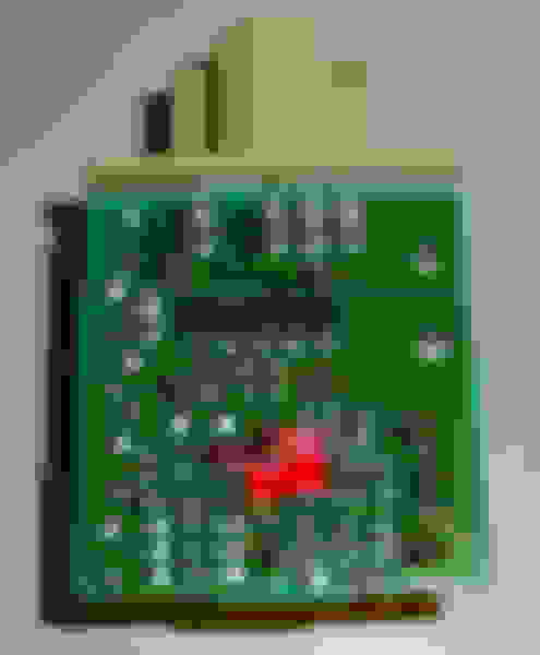
I would also advise people with 1992-1994 SC's with dead flasher relays to NOT throw these faulty electronic parts out for the time being. It's a long shot but I'm going to look into whether or not it is possible to rebuild or reuse any part of them in any conceivable way. We'll see if that's at all possible but given that it seems to be difficult to find examples of this relay part number online right now in good or bad condition I think it's a good idea to keep the physical part for the moment just in case it is possible to re-use any part of it in some way. Again... that's a long shot but what I am interested in is how it is constructed internally, its specific casing and plastic and what electrical values it has.
Here's the reason why I am advising everyone with 1992-1994 SC300/400's to NOT throw away a defective factory 81980-24020 5-pin flasher relay. These are images from various threads relating to the 92-94 SC flasher relays. It's actually a slightly complicated setup in there. However at the same time this is what also makes me wonder if there is a way to fix or rebuild or re-use part of these since the 1992-1994's seem to have no easy off the shelf aftermarket flasher relay solution.
I'm just scouring threads for the 97+ tail light hyperblink fix at this point because this actually gets into the innards of these relays and that *might* give some clues as to how to work on them and maybe even restore or modify them to work again.
I also found this post from O.L.T. in this thread link a while back (relating to 97+ tail lights on a 92-94 to fix the infamous "hyperblink" issue when doing that modification to an early SC) which explains some of the internal function in more detail: https://www.clublexus.com/forums/per...ml#post3144199
Originally Posted by O. L. T.
Cool. I did a thread on here that showed you a modified flasher that was adjustable and you could make it blink at any rate.
That cap does not directly control the flash. The cap feeds the 555 style timer chip and it changes the input to the timer chip, which is what really controls the flashing relays. The cap changes works, but I don't like the way it was went about being done.
You can confuse the chip with too much variance in the capacitor. If you are ever in an accident or need your hazards (which we only need them at the worst times) the chip may become confused if the capacitor value is too far off for the 555 timer to get the proper signal it wants to see to perform the "clock" function it has to do. It can happen with the turn signals just as easily, but not as serious of a situation unless you live in the city. The chip is digital and needs a digital high of +5v and a digital low of 0v. When the capacitor is off too much it undercuts the input voltage and can wig the clock out in the timer chip.
Given that these things are not your average turn signal flasher relay unit I think it's a good idea to hang onto them because it may be possible to open them up and rebuild them by replacing any dead components with capacitors and chips from suppliers like Mouser or Digi-Key and the switching units themselves desoldered and transplanted from another common or similar Toyota/Denso OEM relay.
I'd like to see if that is possible for the 1992-1994 SC300/400 models.
Actually, if O.L.T. happens to see this thread I'd be interested to hear his thoughts on how such a rebuild to normal function again might be possible for those capable of desoldering and soldering with ESD-safe tools.
I mean... if it happens to be as simple as this fix for an OEM Porsche 924/944 relay then great but if repair involves de-soldering and soldering in other internal replacement components then so be it.
Yamae, thank you very much for taking a look at this thread!
I bought two of the aftermarket relays from Rockauto in that link (listed for 1992-1994 model years).
One is a Standard Motor Products / Intermotor EFL9 and the other is a Tridon / Novita EP35 (listed as LED compatible).
Unfortunately both of them are three-pin style relays. They would likely work fine on a late-1994 or 1995-2000 SC (or 1995-2000 Soarer) but they won’t work in place of our oddball 5-pin flasher relays used in the early model years.
The voltage and wattage rating is probably compatible but the pin arrangement and function of each of the five pins on the OEM relay is different from these simpler aftermarket 3-pin relays. From looking at the electrical diagrams a few posts back I think the function is different from most conventional aftermarket 5-pin relays.
When I looked up a video of how to remove the flasher relay from a 1999 SC300 I noticed that the factory relay looks like it might be a three-pin unit but with a cross-over metal piece which turns it into a four-pin when plugged into the car. But this is still very different from the relay configuration and pin layout/function of the 1992-1994 SC flasher relays.
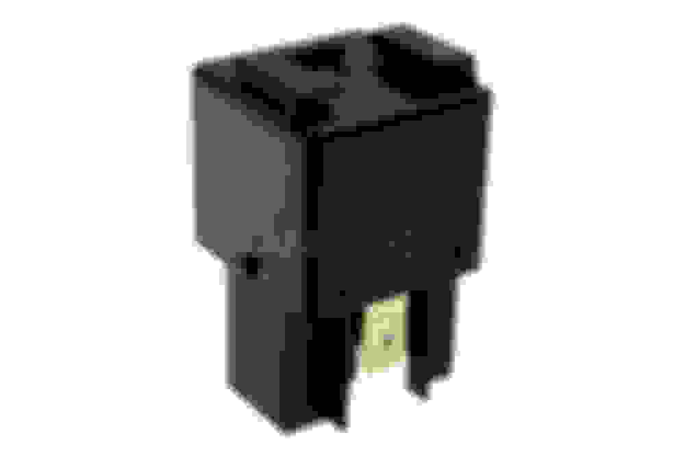
This is the 1992-1994 SC's OEM flasher relay below. The equivalent Soarer Z30 1991-1994 flasher relay looks identical but with a different part number. Both part numbers are discontinued by Toyota now so this shortage of a new replacement flasher relay will affect any 1991-1994 Lexus SC300/400 or 1991-1994 Z30 Toyota Soarer.
5-Pin 1992-1994 SC300/400 (and early Z30 Soarer) flasher relay pinout. This is from the USDM SC300/400 TSRM diagrams and one of the reference pictures posted above.
Pinout From SC300/400 pre-1995 Electrical TSRM:
Pin 3 — 12V to 0V with Turn Signal Switch Left or Hazards ON
Pin 5 — 12V to 0V with Turn Signal Switch Right or Hazards ON
Pin 4 — Continuity with Turn Signal Switch Left or Hazards ON
Pin 2 — Continuity with Turn Signal Switch Right or Hazards ON
Pin 1 — 12V Input with ignition switch or Hazards ON
Inside the casing there are not one but two switching mechanisms:
And according to O.L.T. in a post a few years ago the actual turn signal control and timing is run by a "555 style" digital microchip on the internal logic board in addition to a few capacitors and the wattage sensing circuit (which has had to be modified by owners wishing to switch to LEDs instead of traditional bulbs).
And the above pinout for THIS 81980-24020 Toyota/Lexus flasher relay which was only made for the SC300/400 (and the Soarer variant 81980-24010) does not conform to what a normal Bosch-style 5-Pin automotive relay pinout does. Toyota really did their own thing when they designed this part and its body circuit for the early model years of the SC/Soarer.
So it does seem in this case we will have to look into repairing or rebuilding the OEM turn signal flasher relay for 1992-1994 SC300's and SC400's (and 1991-1994 Z30 Soarers).
I do suspect that once the internal electronic components can be identified that it will be possible to locate new OEM-spec/brand replacements from the right sources and/or steal some bits from other much more common Toyota/Lexus signal flasher relays that can be purchased brand new. But it does mean opening up one of these things, desoldering whichever components have gone bad and soldering in new ones that do the same thing or which are the same internal electronic part.
The alternative is to rewire the car for an entirely different turn signal and hazard circuit and that will be difficult with a circuit board behind the kick panel fuse box in the footwell among other things.
Sorry that my previous post was almost useless. I do understand your serious situations, KahnBB6 and others.
After I replied you this morning, I asked my old friends who had related to old Toyota cars design. I also tried to search the Net some more.
According to my friends, the 5 pin relay uses two relays inside aiming to control bulbs L and R separately to reduce the damage of contacts. There goes a big spike current when bulbs were turned on and this causes some minor damage to contacts. In order to reduce the damage, separate relays are used for higher grade models. I also asked them about the detail of inside the relay unit but no one had any schematics nor any good answer.
My Internet search reached to this site. http://soarer.in/soarer/manual/haisen_1989_1.pdf
The pdf file contains all the circuit diagrams for JDM E-GZ20 and E-MZ20 Soarers. Look at the page 58. Things are all written in Japanese but I'm sure you can find a 5 pin relays there and how bulbs are connected. The characters "ターン シグナル リレー" means "turn signal relay". I think it may be possible to use 2 pf 3pin relays with some modifications instead of the original 5 pin relay.
This is just my guess, when we use 2 relays, the flushing speed becomes slower. We need to do something for this as well as to connect 2 relays to the original 5 pin relay's socket.
Yamae! Thank you, thank you, thank you!!! My apologies for the belated reply. It was an intense day and I couldn't get back to the thread to respond and consider the new information before now. I was in no way pushing you to dig deeper to go to such lengths as contacting other Toyota engineer friends but this is amazing! We're in your debt!!
Based on what your colleagues told you about the 5-pin, twin internal relay design is very interesting. So this was a means of reducing wear over time on the electrical contacts for premium Toyota models. I'd venture a guess that today with almost everything being LED based these current draw concerns would not require such a beefed up electrical design but in 1990 or so this must have been the way to make a signal flasher relay and circuit on a premium car last a VERY long time. Even though it presents a difficult situation at the moment I'm impressed with this idea that was used on some Toyotas from the Z20 through the Z30 eras.
I looked through all of my TSRM schematics for the SC300/400 again but had no luck finding any internal diagram of the twin-unit flasher relay such as you have found for the Z20 Soarer.
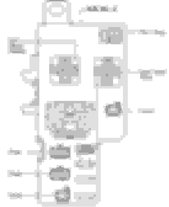
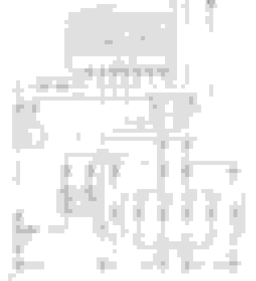
I did find this simplified diagram the day before yesterday but it was already posted above as an attachment. I'll put it in this post anyway just for reference:
^^ But as you can see, neither in this simplified SC300/400 Turn Signal schematic or the more detailed black-and-white schematic of the same circuit in the previous post above has any detail of how the internals of the 5-pin flasher relay actually works.
From your Z20 5-pin flasher diagram we can see the logic at work that the engineers wanted us to understand even if there are no schematics of the inside of it. So that along with the pinout that we have for the North American SC (and by extension I assume the JDM Z30 Soarer) should tell us what function needs to get assigned to which pin and how the twin relays need to be wired to individually handle the Left and Right signals and Hazard Flash functions.
But I think this brings us to the digital chip inside this relay. I think that is what needs to be wired to from the five contact pins on the outside of the relay and from the chip we would need to wire the relay pins themselves. That leaves the question of which pin does what on the digital controller chip?
For that, I think we will need a donor SC flasher relay to inspect carefully especially where this chip is. I have located a used one yesterday which I should be receiving in the mail soon. I will take many high resolution closeup pictures of its internal configuration and attempt to map the circuit board, the digital controller chip pins and which other components they connect to.
As a bonus, I have a spare 1992 SC driver's side fuse block footwell kick panel coming in complete with the "integration relay" that is housed on the back of it. This will provide a way to test at least the fitment of the relay and perhaps even some electrical connections to the flasher relay. Hopefully.
Now... I am somewhat familiar with working on small electronics and I am comfortable working on automotive electrical wiring and looking at electrical circuit reference diagrams to sort out issues or rewire an engine harness... but some aspects of basic electronics design and what some terms mean are still new to me.
When you say "flushing speed"... can you explain what this means? Is this to do with the speed at which the 12V-to-0V-to-12V switching sequence of the relay can occur?
I am still thinking in terms of Option A being to repair the factory relay unit in some way and Option B being the custom/aftermarket twin aftermarket relay solution you suggest is possible. And honestly I think you're right-- there probably is a way to do this with two simple 3-pin aftermarket relays once we can figure out how to control them and time them (with capacitors I assume).
When I have the spare SC flasher relay in hand after it arrives I will open it up and look. I am thinking... other than some fine tuning with different electrolytic capacitors and the wattage-sensing circuit also included.... the way to control two aftermarket relays may come back to the way Toyota officially did this: by routing the five pin functions through a digital controller microchip which then doles out the switching logic and decisions to each of the two relays. And I am willing to bet that the two OEM internal relays are of a very simple design... maybe only three pins each (internally x2).
And if pictures of the OEM relay internals prove this to be correct then it will line up right along with your custom aftermarket idea to use two simple aftermarket 3-pin relays once we can figure out a way to control them.
Another thing is that once I have the spare fuse kick panel to set up on my workbench I can confirm whether or not a standard Bosch-style 5-pin relay can physically connect into that space. Then... even though we would need to modify it internally and gut it basically this might serve as a basis to completely rewire the internal side of the aftermarket 5-pin relay with your idea. Maybe at that point a 3D printed casing would be needed... or maybe the original flasher relay casing would be needed.
At the same time I also want to catalog and identify each electronic part inside the OEM relay in case new components can be sourced.
I am thinking out loud and brainstorming. Perhaps I am getting ahead FAR of myself, lol. I feel like I'm throwing in every piece of information I can think of at the moment.
I am going to sleep on this and give it some more thought but as before I am very curious as to what you may think about this so far and if any of the above ideas seem to you closer to the mark or farther off the mark to a good and reliable solution.
It will take a few days until I will receive the spare flasher relay in the mail. Once I get it I will start taking detailed pictures of the inside and posting them here.
Again, Yamae, thank you very much for helping to looking into this with us and sharing your expertise and experience!
This afternoon I received a junkyard spare 81980-24020 92-94 SC flasher relay in the mail. With it I also picked up a footwell fuse panel from a 1992 SC that it will fit. This should allow a good base for fitment testing of any non-original relay casing, of any aftermarket 5-pin relay base and of the relay behavior from the pins with the unit energized.
I also got a reply from O.L.T. which confirms early suspicions of how this relay was designed electrically and of how it controls the timing interval of each turn signal's flash.
Originally Posted by O. L. T.
...here�s the basic jist. Capacitors control the timing. A custom one would depend on every single variable, so ground up build from your specifics (resistance, load, etc). There�s no go to amount of capacitance. Blink rate is how fast the caps discharge. That�s different for every bulb.
As a hunch, this *may possibly* explain a potential failure point in these relays if a failed or failing electrolytic capacitor (of which several in concert control flash timing) allows no flash or some other abnormality. For the moment that is just my hypothesis. I do think we at least *should* be able to source new replacement capacitors and resistors in exactly the right kind that are needed per the OEM specification.
The small microchip controller inside also has to be figured out as to exactly what it does and how it does it. Since the capacitors are what control the actual blink timing and duration maybe this chip only assigns the Left, Right and Hazard assignments between the two relays and the five external interface pins?
I'm tied up this weekend and on Monday but after that I should have some time to open up the flasher relay and start investigating it in-depth.

 07-15-15 | 10:07 PM