How to make this work?
 09-15-05, 04:19 PM
#61
Lexus Fanatic
iTrader: (20)
Originally Posted by GILLEXUS
What is your "TH-Point" set to? go to main menu then "setting mode" then 3."TH-Point"
what does ti show for Throttle Lo% and Hi %
what does ti show for Throttle Lo% and Hi %
does yur RPM on your S-AFC match the car tach?
But here's the good news. Finally, I watched the MONITORED throttle with the ENGINE RUNNING, and foot to the floor it DOES show 100%, plus in sensor check the voltage does seem to go to almost 4v for throttle.
Maybe my battery is kinda wimpy when the engine's off and that's what's gives me the low voltage read when the engine is off?
I just used the wire diagram from SRT's GS400 instructions and added the S-AFC wiring info to it. Yours shoud match the wires coming from the SRT ECU box in the diagram. I'll also look at your pic and see if I can tell what is tapped into.
Thanks to everyone.
 09-15-05, 04:22 PM
#62
Originally Posted by GILLEXUS
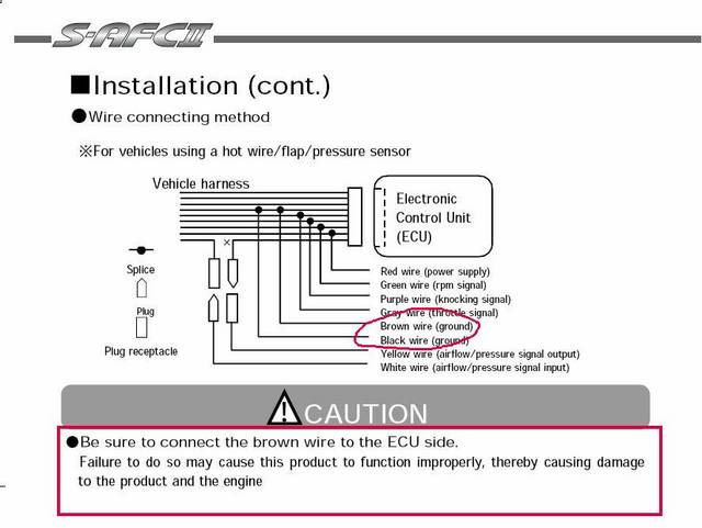
Paul I think I see a problem.. Con firm for me is the brown and black wire from the S-AFC the ones circled in the pic?
If so looks like they a attached togather onto the brown ECU wire?? If that is correct the manual specificlly states that they have to be atleast 1cmor 1/2" apart.
Unwrap those 2 wires and see if they are together. It doesnot look like there is enough room under that tape tobe too far apart.

If so looks like they a attached togather onto the brown ECU wire??
If that is correct the manual specificlly states that they have to be atleast 1cmor 1/2" apart. Unwrap those 2 wires and see if they are together. It doesnot look like there is enough room under that tape tobe too far apart.
You are right - I didn't notice until you said that. Yes, that section you have circled is coming off the S-AFC. Paul you have the right wires used and have pink and orange taped up.
Can you see what the grey wire from the S-AFC is attached to?? Is it red/black?
Jonny
 09-16-05, 04:00 PM
#64
Originally Posted by GILLEXUS
Jonny did my schematic help??
Doesn't it look like Paul has the black and brown S-AFC wire connected together to the brown ground stock ecu wire ?? These should be separated.
Doesn't it look like Paul has the black and brown S-AFC wire connected together to the brown ground stock ecu wire ?? These should be separated.
Yeah, you are right - it isn't done right. However, I don't know how much that would have to do with his inaccurate readings. From what I understood that grounding thing was done as a backup for a large surge and that is why they were supposed to be at least 1 cm apart. I asked him about his grey wire but have not heard a response yet.
Yes, thank you for the schematic. I think I posted my one right at the same time you posted yours - great minds do think alike

As for the picture of the jumper - please explain.
Firstly, what kind of connector is that you used.
Secondly, I don't understand how this is tying into the S-AFC?
Jonny
09-16-05, 08:28 PM
#65
Lexus Fanatic
iTrader: (20)
Originally Posted by GILLEXUS
Paul I think I see a problem.. Con firm for me is the brown and black wire from the S-AFC the ones circled in the pic?
If so looks like they a attached together onto the brown ECU wire?? If that is correct the manual specifically states that they have to be at least 1cm or 1/2" apart.
Unwrap those 2 wires and see if they are together. It doesnot look like there is enough room under that tape tobe too far apart.
If so looks like they a attached together onto the brown ECU wire??
If that is correct the manual specifically states that they have to be at least 1cm or 1/2" apart. Unwrap those 2 wires and see if they are together. It doesnot look like there is enough room under that tape tobe too far apart.
 Looks like they're both connected to the brown wire going into the wiring block!? Does it mean they should be spliced in at different points along the wire going into the block?? [/QUOTE]
09-16-05, 08:33 PM
Looks like they're both connected to the brown wire going into the wiring block!? Does it mean they should be spliced in at different points along the wire going into the block?? [/QUOTE]
09-16-05, 08:33 PM
#66
Lexus Fanatic
iTrader: (20)
Originally Posted by Dx3
Can you see what the grey wire from the S-AFC is attached to?? Is it red/black?
09-16-05, 08:39 PM
#67
Lexus Fanatic
iTrader: (20)
Originally Posted by GILLEXUS
I just used the wire diagram from SRT's GS400 instructions and added the S-AFC wiring info to it. Yours shoud match the wires coming from the SRT ECU box in the diagram. I'll also look at your pic and see if I can tell what is tapped into.
Sorry for my lack of understanding, I didn't install the thing and thus have never spent any time trying to understand the wiring at all and now I look at yours and Jonny's diagrams and a jungle of wires in the box and it's hard to figure out!
I guess now I have to really waste a bunch of time to figure it out. Sigh...
 09-16-05, 10:00 PM
#68
Originally Posted by bitkahuna
Jonny, I didn't leave that cover off and have been busy so I haven't had time to get it open again and look at the wires. I'll get to it. Thanks.
Jonny
09-16-05, 10:14 PM
#69
Originally Posted by bitkahuna
In looking at the pic (I haven't had chance to open my ECU cover again) it definitely looks like that's the brown and black wires coming from the SAFC-2. But how can they be 'apart' if they're both connected to the same wire!? Looks like they're both connected to the brown wire going into the wiring block!? Does it mean they should be spliced in at different points along the wire going into the block??
Looks like they're both connected to the brown wire going into the wiring block!? Does it mean they should be spliced in at different points along the wire going into the block?? Bit - these wires coming from that set are your S-AFC wires. I checked them against mine and they are the S-AFC wires.
By apart what we mean is this. The stock ground wire on the car is brown. When your SAFC was installed the only actual wires that are cut are your input sensors - MAF.
The rest of the wires are actually just stripped of their plastic cover and soldered on - as if creating a Y shape.
Well, on this particular setup, think of it this way. If you laid out a ruler and laid your stock ground wire on it. You go 7 inches in on the stock ground and strip the brown cover and solder in the wire. Well, the SAFC has 2 grounds for safety precautions. Instead of wiring them both in at the same point, they tell you to connect them at different points on the stock ground, at least 1cm apart.
Here is a very quick sketch to explain.
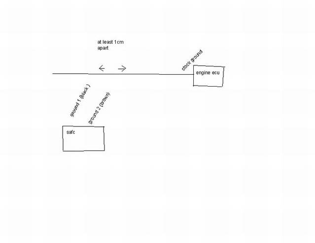
Hope this helps man.
Jonny
09-16-05, 10:21 PM
#70
Originally Posted by bitkahuna
Sorry Gil - I don't get it at all - your diagram shows NO wiring going from the SRT ECU to the wiring block and only the green and purple SAFC2 wires going to the block.
Sorry for my lack of understanding, I didn't install the thing and thus have never spent any time trying to understand the wiring at all and now I look at yours and Jonny's diagrams and a jungle of wires in the box and it's hard to figure out!
I guess now I have to really waste a bunch of time to figure it out. Sigh...
Gil's diagram shows all of the wiring that the SRT uses, and then the only differences on the SAFC are the green and purple.
His diagram shows ALL of the wiring from the SER ECU to the wiring block, not NO wiring
 Basically you have to put the 2 together. For instance, look at the SRT ECU. The first one is the 12v. OK, now look on the top left of the diagram on the wiring block and you will see the 12v black red. Therefore, this is telling you that the RED wire from the SRT ECU is the 12v, it will attach on the wiring block with the black/red wire and you will find this red/black wire on the 2nd connector on the very first pin.
Hope this explains everything. If not, give me a call and I will explain it over the phone. PM me for number.
Take care,
Jonny
09-17-05, 06:11 AM
#71
Lexus Fanatic
iTrader: (20)
Originally Posted by Dx3
Bit - the wire I mentioned is your TP wire so I figured that you should start there to find out your problem with inaccurate throttle readings.
Jonny
Jonny
 Weird...
09-17-05, 10:49 AM
Weird...
09-17-05, 10:49 AM
#72
Gil,
Was just thinking about this. If you keep the SRT ECU MAF connected ( input and output) and disconnect the rest of the SRT ECU then how is the MAF going to have any power. Surely you would have to keep the power from the SRT ECU connected to run the MAF?
Jonny
Was just thinking about this. If you keep the SRT ECU MAF connected ( input and output) and disconnect the rest of the SRT ECU then how is the MAF going to have any power. Surely you would have to keep the power from the SRT ECU connected to run the MAF?
Jonny
 09-20-05, 09:13 AM
#74
Hey Jonny,
Sorry for the delay I was doing another diagram for you to help clarify what I was saying. I'm at work now I'll send it when I get home. What I mean is to keep the SRT harness connected and disconnect the SRT ECU box. Your right the signal coming from the MAF sensor is no longer going to the car's ECU because that wire was cut and the SRT wire harness was put in.
That is the purpose of the jumper wire to complete the signal flow from the green SRT wire to the orange SRT since the SRT ECU box is gone.
I hope this helps. I think the new diagram I make will simplify things. You'll see what I mean by the S-AFC has to be wired AFTER the SRT MAF wiring
You mention the MAF having power, Do you mean the SRT ECU box having power?? The MAF ( mass Air flow) is attached to the intake tube and it is running off the cars ECU. With the SRT ECU box disconnected it will not send the MAF sensor signal to the car's ECU but if you put a jumper wire in the SRT wire harness it will.
Ron G.
Last edited by GILLEXUS; 09-20-05 at 06:22 PM.
09-20-05, 01:22 PM
#75
Originally Posted by GILLEXUS
Bitkahuna,
Check and see that the gray ( throttle wire) is connected to the right spot. I guesing that your not recieving the proper signal?
Morris,
Can you check and see what voltage # your getting on your throttle in the sensor check mode? I do beleive the 400 and 430 use the same TPS and throttle body. I get 3.99 - 3.94 volts reading when my throttle is fully opened.
Morris.