
2GS 2jzge-t T61 build thread
 02-02-08, 10:03 PM
#1
About time that i posted pics... hnoes:
Before we start, make sure you know what is your goal. It's hard to build your foundations if you don't know how high of a building you want to create. Delicate hand and a factory service manual is a must. There's a 95 supra one on this site, and a '05 is300 one on my.is. They both should cover sc's and gs's in terms of drivetrain.
In my case, I decided to do an engine tune-up, including 1.3mm headgasket, new seals, gaskets, timing belt, etc. I bought a HG kit that included every gasket and seal for the 2jz. These cometic-like 3 layer headgaskets COULD be re-used after slight use, but I highly do not recommend it. Be prepared to spend a day to remove everything, and another day to clean the surface and reassembly.
Drain your coolant. There's a drain plug on the block underneath the exhaust manifold. Use a 14mm wrench to open it. It is important for you to drain all the coolant inside the block if you're going to open it.

Intake removed

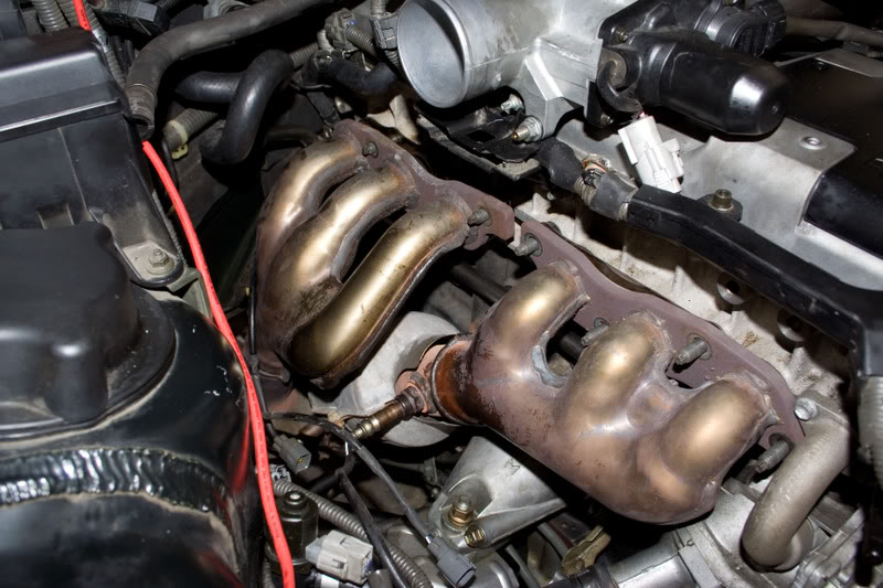
Exhaust being removed
There's 2 coolant lines, 4 electric plugs, 3 big vacuum lines, and 2 small vacuum lines (1/8"), 1 throttle cable, plunged into your TB/Y-pipe assembly. I don't have detailed pics but the factory service manual should be more than enough. The 2 small vacuum lines are harder to find because they're underneath the Y-pipe.
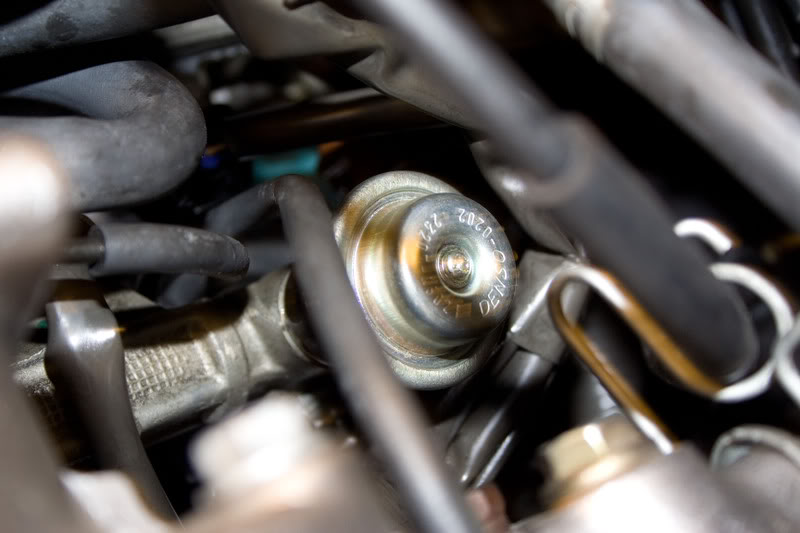
Remove Fuel Pressure Dampener
Stock 2jzge w/ vvti does not have an fuel return line. The FPR is in-tank, and the pressure is regulated through a pressure signal. The dampener acts as a buffer to make fuel flow even smoother when it gets to the fuel rail. You must remove this in order to remove the fuel rail and then the lower runners. Be careful because there's a metal gasket right underneath the black ring feed line.
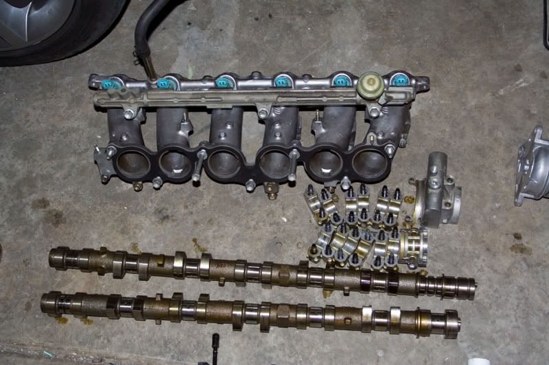
Intake manifold removed
*note: There are 3 bolts hidden under the lower runners bolted to the head. They are very hard to find...so use your hands and feel them up.

Coil-on-plug/distributor hybrid ignition. 3 Main units, 3 distributor wires, 6 firing plugs total. Why is it so weird? You'll see later. Honestly it's ingenious.

Valvecover and Camshafts removed.
*note: ply the first cam bearing (vvti unit) towards you, not away from you. You'll crack the 2 small allen wrench holes if you ply away from you.
*camshaft bearings must be removed in a special sequence and be re-used in the same order! There are very tiny letters laser-etched on the metal surface, they go in specific order, check with your FSM.

Oh Hi I have your internalz
hnoes:Before we start, make sure you know what is your goal. It's hard to build your foundations if you don't know how high of a building you want to create. Delicate hand and a factory service manual is a must. There's a 95 supra one on this site, and a '05 is300 one on my.is. They both should cover sc's and gs's in terms of drivetrain.
In my case, I decided to do an engine tune-up, including 1.3mm headgasket, new seals, gaskets, timing belt, etc. I bought a HG kit that included every gasket and seal for the 2jz. These cometic-like 3 layer headgaskets COULD be re-used after slight use, but I highly do not recommend it. Be prepared to spend a day to remove everything, and another day to clean the surface and reassembly.
Drain your coolant. There's a drain plug on the block underneath the exhaust manifold. Use a 14mm wrench to open it. It is important for you to drain all the coolant inside the block if you're going to open it.
Intake removed
Exhaust being removed
There's 2 coolant lines, 4 electric plugs, 3 big vacuum lines, and 2 small vacuum lines (1/8"), 1 throttle cable, plunged into your TB/Y-pipe assembly. I don't have detailed pics but the factory service manual should be more than enough. The 2 small vacuum lines are harder to find because they're underneath the Y-pipe.
Remove Fuel Pressure Dampener
Stock 2jzge w/ vvti does not have an fuel return line. The FPR is in-tank, and the pressure is regulated through a pressure signal. The dampener acts as a buffer to make fuel flow even smoother when it gets to the fuel rail. You must remove this in order to remove the fuel rail and then the lower runners. Be careful because there's a metal gasket right underneath the black ring feed line.
Intake manifold removed
*note: There are 3 bolts hidden under the lower runners bolted to the head. They are very hard to find...so use your hands and feel them up.
Coil-on-plug/distributor hybrid ignition. 3 Main units, 3 distributor wires, 6 firing plugs total. Why is it so weird? You'll see later. Honestly it's ingenious.
Valvecover and Camshafts removed.
*note: ply the first cam bearing (vvti unit) towards you, not away from you. You'll crack the 2 small allen wrench holes if you ply away from you.
*camshaft bearings must be removed in a special sequence and be re-used in the same order! There are very tiny letters laser-etched on the metal surface, they go in specific order, check with your FSM.
Oh Hi I have your internalz
Last edited by ElitistK; 02-02-08 at 10:10 PM.
 02-02-08, 10:04 PM
#2
Head removed
*There are 14 headbolts holding the head to the engine, and every one of them must be removed in a special sequence, otherwise you will wrap your head.
*Now you see how the coil-on-plug/distributor hybrid is created. The 2jz runs in pairs, 1-6 2-5 and then 3-4. Main units are seated on 2-4-6 cylinders, while unit 2 runs a wire to 5, unit 4 runs a wire to 3, and unit 6 runs a wire to 1.

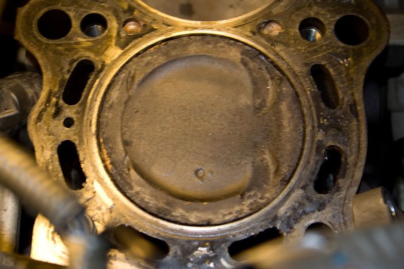
Piston 1 at crankshaft pulley TDC

Piston 1 true TDC
I got some NGK BKR6ES from my local pepboys (they didn't have the 8E so i went with a hotter plug). Next time around i'll over the BKR8ES (6 series).

To clean the aluminum head surface, use your favorite credit card that you have banned from your financial life. To clean the iron block surface...you can use pretty much anything you want (except things that are more abrasive than iron, duh). Reassembly is in reverse order. Don't forget to double check everything before you fire it up
*There are 14 headbolts holding the head to the engine, and every one of them must be removed in a special sequence, otherwise you will wrap your head.
*Now you see how the coil-on-plug/distributor hybrid is created. The 2jz runs in pairs, 1-6 2-5 and then 3-4. Main units are seated on 2-4-6 cylinders, while unit 2 runs a wire to 5, unit 4 runs a wire to 3, and unit 6 runs a wire to 1.
Piston 1 at crankshaft pulley TDC
Piston 1 true TDC
I got some NGK BKR6ES from my local pepboys (they didn't have the 8E so i went with a hotter plug). Next time around i'll over the BKR8ES (6 series).
To clean the aluminum head surface, use your favorite credit card that you have banned from your financial life. To clean the iron block surface...you can use pretty much anything you want (except things that are more abrasive than iron, duh). Reassembly is in reverse order. Don't forget to double check everything before you fire it up
02-02-08, 10:05 PM
#3
Now the turbo install...
The kit..

T61 T4 Turbocharger
Turbine: .84 AR, 3" v-band outlet.
Compressor: .70 AR, 4" inlet, 2.5" outlet.
40mm wastegate
27x7x3 Intercooler
TiAl-style 50mm BOV
2.5" piping
3" Downpipe
AEM UEGO wideband sensor
AEM F/IC piggyback
1.3MM HG
550cc SARD injectors (not installed until later)
Test dry-fit everything. It's almost like Lego's, and you can see the clearance in between everything so when it goes into your car, you'll know what you really need.
Drain your engine oil. You won't be reusing this oil so it's best to get new oil and a new filter while you're at it.
Here's the oil feed tap. Do not eliminate this sensor.

This..
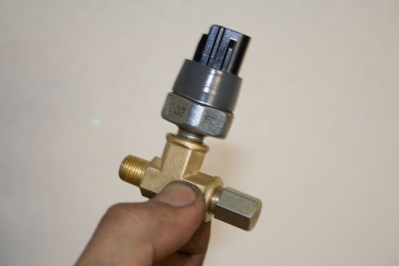
Will go into where the sensor is.

The reason why I did it is because the wiring isn't long enough to reach all the way out there. If you put the first fitting onto the second fitting, it will be long enough to reach the sensor as long as it's at 9-12'o clock position.
Here's the complete picture.

Oil return plate
*Make your return hole at least 1/2". I highly recommend 5/8" though. Use a step drill-bit with a lot of multi-purpose grease (you want to lubricate and cool the hole so you don't grab onto the soft aluminum pan). Also picks up the shavings so not a big amount goes inside your upper pan (which can be catastrophic).
*Don't be lazy and do a drill AND THEN tap procedure for the 2 M8 holes. The bit that I used drills and taps and it seems to ****ed up the upper hole.
*Remove the thermostat unit to drill the upper hole. I doubt you have a drill that is small enough to fit in there AND also be powerful enough to drill on it. Some coolant will come out so be prepared.
*Use your favorite high temperature sealant as gasket. Be generous but make sure the sealant doesn't get into the oil pan!
*Flush out the metal shavings with your drain line, attached to the drain plate, and your used oil. Just don't forget to have a bucket to catch it. You WILL see shavings coming out, the more the merrier.

I highly recommend upgrading your feed and drain lines. -4AN for feed and -8AN for drain
(From Jegs.com)
Feed list (don't need NPT to -AN adapter)
555-100050 #4 STR HOSE END PUSH LOC
555-102200 #4 PUSH LOC HOSE 5' BLUE (or whatever length you need)
Drain list
555-100129 1/2"NPT TO #8 FLARE 45 degree bend
555-100107 3/8"NPT TO #8 FLARE
555-100052 #8 STR HOSE END PUSH LOC
555-102220 #8 PUSH LOC HOSE 5' BLUE (or whatever length you need)*
*People usually run -6AN for their fuel system, but if you decide you want to flow more, then you can go up to -8AN and buy like 20 ft. of this stuff.
Intercooler install:
If you have the 27x7 small and cute intercooler (that flows a lot of air), you're going to have to drill your own hole and customize mounting brackets. Home Depot is the answer.
Mount the brackets onto the intercooler, and then mount the entire assembly...

Onto this...

Complete picture

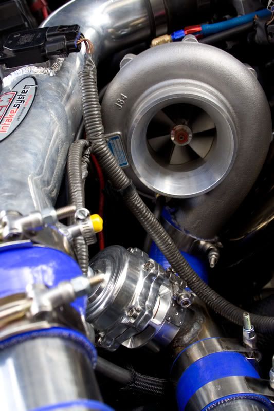
Turbo install:
This has been covered so many times, i'm just going to go over a few highlights.
-Make sure you rotate the turbo housing (by loosing the 4 bolts behind the turbine) to get to the 4th inner most nut that is impossible to get with a rachet. It's ok to not put that much torque onto the nut because the weight distribution makes the turbo want to lean out, not lean in.
-Careful not to get teflon tape into the oil system. Again, upgrading your drain lines to -AN fittings will solve a lot of these oil weeps and leak headaches (besides, it looks nice with the blue and the red and the light blue and the easiness of install/uninstall).
-If you have a better oil gasket, use it.
-Take off the compressor for easier installation and also drill a 21/64" hole and tap 1/8" NPT fitting onto the housing. You will need to run a positive pressure sensor to the fitting on the wastegate, otherwise your wastegate will never open.
-Make sure you put the giant o-ring on the compressor first, and then you put the housing over.
-Dry fit your downpipe to see if the v-band will fit over the turbine and the downpipe. If you're downpipe is way too thick, you can either cut the original flange and weld on a new one, or grind it down and use a gasket. I would recommend to cut the flange, grind it on the non-contact side, and then re-weld it. Use a gasket anyways.
-Use tabs of sealant around the flange for the TiAl 50mm o-ring. You'll see why.
I had the most problem with intercooler piping during my install, so here is mine:
I really like the TiAl style BOV. Besides, it sounds nice.
The kit..
T61 T4 Turbocharger
Turbine: .84 AR, 3" v-band outlet.
Compressor: .70 AR, 4" inlet, 2.5" outlet.
40mm wastegate
27x7x3 Intercooler
TiAl-style 50mm BOV
2.5" piping
3" Downpipe
AEM UEGO wideband sensor
AEM F/IC piggyback
1.3MM HG
550cc SARD injectors (not installed until later)
Test dry-fit everything. It's almost like Lego's, and you can see the clearance in between everything so when it goes into your car, you'll know what you really need.
Drain your engine oil. You won't be reusing this oil so it's best to get new oil and a new filter while you're at it.
Here's the oil feed tap. Do not eliminate this sensor.
This..
Will go into where the sensor is.
The reason why I did it is because the wiring isn't long enough to reach all the way out there. If you put the first fitting onto the second fitting, it will be long enough to reach the sensor as long as it's at 9-12'o clock position.
Here's the complete picture.
Oil return plate
*Make your return hole at least 1/2". I highly recommend 5/8" though. Use a step drill-bit with a lot of multi-purpose grease (you want to lubricate and cool the hole so you don't grab onto the soft aluminum pan). Also picks up the shavings so not a big amount goes inside your upper pan (which can be catastrophic).
*Don't be lazy and do a drill AND THEN tap procedure for the 2 M8 holes. The bit that I used drills and taps and it seems to ****ed up the upper hole.
*Remove the thermostat unit to drill the upper hole. I doubt you have a drill that is small enough to fit in there AND also be powerful enough to drill on it. Some coolant will come out so be prepared.
*Use your favorite high temperature sealant as gasket. Be generous but make sure the sealant doesn't get into the oil pan!
*Flush out the metal shavings with your drain line, attached to the drain plate, and your used oil. Just don't forget to have a bucket to catch it. You WILL see shavings coming out, the more the merrier.
I highly recommend upgrading your feed and drain lines. -4AN for feed and -8AN for drain
(From Jegs.com)
Feed list (don't need NPT to -AN adapter)
555-100050 #4 STR HOSE END PUSH LOC
555-102200 #4 PUSH LOC HOSE 5' BLUE (or whatever length you need)
Drain list
555-100129 1/2"NPT TO #8 FLARE 45 degree bend
555-100107 3/8"NPT TO #8 FLARE
555-100052 #8 STR HOSE END PUSH LOC
555-102220 #8 PUSH LOC HOSE 5' BLUE (or whatever length you need)*
*People usually run -6AN for their fuel system, but if you decide you want to flow more, then you can go up to -8AN and buy like 20 ft. of this stuff.
Intercooler install:
If you have the 27x7 small and cute intercooler (that flows a lot of air), you're going to have to drill your own hole and customize mounting brackets. Home Depot is the answer.
Mount the brackets onto the intercooler, and then mount the entire assembly...
Onto this...
Complete picture
Turbo install:
This has been covered so many times, i'm just going to go over a few highlights.
-Make sure you rotate the turbo housing (by loosing the 4 bolts behind the turbine) to get to the 4th inner most nut that is impossible to get with a rachet. It's ok to not put that much torque onto the nut because the weight distribution makes the turbo want to lean out, not lean in.
-Careful not to get teflon tape into the oil system. Again, upgrading your drain lines to -AN fittings will solve a lot of these oil weeps and leak headaches (besides, it looks nice with the blue and the red and the light blue and the easiness of install/uninstall).
-If you have a better oil gasket, use it.
-Take off the compressor for easier installation and also drill a 21/64" hole and tap 1/8" NPT fitting onto the housing. You will need to run a positive pressure sensor to the fitting on the wastegate, otherwise your wastegate will never open.
-Make sure you put the giant o-ring on the compressor first, and then you put the housing over.
-Dry fit your downpipe to see if the v-band will fit over the turbine and the downpipe. If you're downpipe is way too thick, you can either cut the original flange and weld on a new one, or grind it down and use a gasket. I would recommend to cut the flange, grind it on the non-contact side, and then re-weld it. Use a gasket anyways.
-Use tabs of sealant around the flange for the TiAl 50mm o-ring. You'll see why.
I had the most problem with intercooler piping during my install, so here is mine:
I really like the TiAl style BOV. Besides, it sounds nice.
Last edited by ElitistK; 02-04-08 at 06:53 AM.
02-02-08, 10:05 PM
#4

Get a 2.5" hole saw to cut the plastic, lol.

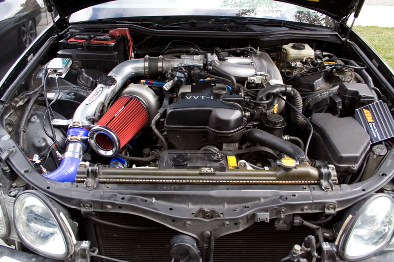
2.5" Piping is so much easier because it can fit between your chassis and headlight. Besides the turbo outlet and the intercooler are both 2.5", so why 3?


I utilized the AEM intake pipe in this setup for MAF's sake. I did not alter the intake pipe so I end up using a 90 degree coupler so it goes straight to the intake pipe. The intake pipe is 3" so you'll need a 2.5 to 3 adapter (TB opening is about 3" as well).

This was my source for erratic idle. DO NOT CONNECT THAT VACUUM TO THAT HOLE! again, PLUG THAT HOLE UP WITH A PLUG AND ALUMINUM BAND!!!!!!!111ONE

I still can't fit my bumper over my car, but that will change very soon :thefinger:
Exhaust being made, I couldn't take any more pictures because the owner was not comfortable with the camera around when they are doing a favor for me :wink:. Anyways, just have an exhaust shop to chop off your stock B pipe, and replace it with a 3" pipe to your cat. The cat opening is about 2.75".

One more before we go onto piggyback install..
Trending Topics
 02-03-08, 01:07 AM
#9
Man everyone is boosting now? Did I start a movement here on CL for NA-T 
Looking good man. Here's a few tips from all of my experience. Don't take this offensively but most of the piping and routing of everything can be cleaned up more. But it's mainly just for cosmetic reasons. If you're not taking the car to car shows then no need to worry. Only reason I mention this is because I used to have some seriously GHETTO RIGGED intercooler piping setup with a HKS SSQV BOV that was held on with 2 hose clamps and some epoxy lol!
Your current setup looks good for up to around 10-12psi or so. More than that the reducing coupler where the IC pipe meets the throttle body will blow in half...trust me I know. I had that same AEM intake and I blew that non reinforced coupler in half with 20psi. Also I think that intercooler will be heatsoaked once you reach around the 350-400whp mark. Plan to upgrade the IC if you want more power than that. Transmission will also need some tweaks at around the 350+ mark. Also, it's better to have the BOV closer to the throttle body, looks like you have yours mounted right after the turbo. It should still be fine though, just make sure the BOV is before the MAF so you don't stall every time it vents.
Everything else looks pretty good for your first DIY setup. Good choice in the FIC for a piggyback. I've worked with that system and it works well and not too hard to street tune. Make sure you get a patch harness so you don't have to hack up your stock harness. Good luck on the rest of your build!
BTW: If you need the wiring diagram for the piggy to stock ecu. I think I have a harness pinout chart on my website. The 12v+ is mixed up...I still have to fix it. Everything else is correct though...but make sure you double check every value with the factory manual first.
02-03-08, 10:53 AM
#12
I had to get universal piping and do some cut to fit work. As you can see on the hot side to intercooler...i made some bad measurements and I end up having to weld an extension to my bend. Other than that, other measurements fit in perfectly.
10-11psi. Keeping it under 350 before i decide what to do with my auto tranny
Yeah, my piping isn't exactly the cleanest right now, but i'm surprised that I only needed one weld to complete it; my measurements actually worked out pretty well. As you can see, my current setup is limited around 350-400rwhp simply because any more than that range, I will need new rods, a built tranny, etc. So I don't see the need of building some things to go past that mark, when my important components simply cannot go that far.
The reason why I placed the TiAl style bov right after the turbo is because many people are having compressor surge issues when placed on the cold side on the intercooler. Placing it on the hot side protects the turbo better, but you lose out some response in between shifts. For me, i can barely tell a difference so I decided to play it safe. Besides in the future, I can just add another BOV on the cold side if I'm really running more then 20-25psi.
BTW Jeff did you have to add a fuel return line with an upgraded pump and an rising presure FPR when you were at 11psi (build your fuel system)? I really don't want to invest that much in the fuel system unless i'm going on to the next "stage". I'm also thinking about just running meth injection for the time being.
Yep, from Mark.
Thanks guys.
10-11psi. Keeping it under 350 before i decide what to do with my auto tranny
Man everyone is boosting now? Did I start a movement here on CL for NA-T
Looking good man. Here's a few tips from all of my experience. Don't take this offensively but most of the piping and routing of everything can be cleaned up more. But it's mainly just for cosmetic reasons. If you're not taking the car to car shows then no need to worry. Only reason I mention this is because I used to have some seriously GHETTO RIGGED intercooler piping setup with a HKS SSQV BOV that was held on with 2 hose clamps and some epoxy lol!
Your current setup looks good for up to around 10-12psi or so. More than that the reducing coupler where the IC pipe meets the throttle body will blow in half...trust me I know. I had that same AEM intake and I blew that non reinforced coupler in half with 20psi. Also I think that intercooler will be heatsoaked once you reach around the 350-400whp mark. Plan to upgrade the IC if you want more power than that. Transmission will also need some tweaks at around the 350+ mark. Also, it's better to have the BOV closer to the throttle body, looks like you have yours mounted right after the turbo. It should still be fine though, just make sure the BOV is before the MAF so you don't stall every time it vents.
Everything else looks pretty good for your first DIY setup. Good choice in the FIC for a piggyback. I've worked with that system and it works well and not too hard to street tune. Make sure you get a patch harness so you don't have to hack up your stock harness. Good luck on the rest of your build!
BTW: If you need the wiring diagram for the piggy to stock ecu. I think I have a harness pinout chart on my website. The 12v+ is mixed up...I still have to fix it. Everything else is correct though...but make sure you double check every value with the factory manual first.
The reason why I placed the TiAl style bov right after the turbo is because many people are having compressor surge issues when placed on the cold side on the intercooler. Placing it on the hot side protects the turbo better, but you lose out some response in between shifts. For me, i can barely tell a difference so I decided to play it safe. Besides in the future, I can just add another BOV on the cold side if I'm really running more then 20-25psi
.BTW Jeff did you have to add a fuel return line with an upgraded pump and an rising presure FPR when you were at 11psi (build your fuel system)? I really don't want to invest that much in the fuel system unless i'm going on to the next "stage". I'm also thinking about just running meth injection for the time being.
Yep, from Mark.
Thanks guys.

