When you click on links to various merchants on this site and make a purchase, this can result in this site earning a commission. Affiliate programs and affiliations include, but are not limited to, the eBay Partner Network.
I have an 07 RX400h. This may work on 330’s or 350’s of similar years.
After someone in my house made a trip to Home Depot for some lumber (even though we also have a Tacoma), I noticed the top of the rear center seat/console broken off, along with the lever that releases the center seat/console from the RH Seat.
There is a post here but I didn’t feel like it was a step-by-step so I figured I’d take pics and do a writeup. I’m not sure how common this is but fixing this isn’t intuitive so here goes!
Most of the time I fixed this, except towards the end, the center seat was in the down position. I’ll try to stay consistent w/my wording, but sometimes I’ll refer to the ‘back’ or the ‘top’ as the same thing. I’ll try to refer to the carpeted piece as ‘the back’. Also, Right and Left are positions as if you’re sitting in the car as per industry standards. If I use the word “Top Cover”, I’m talking about the Plastic Center Cover that’s missing on the first pic. The main plastic Lever mounts into the Right side of this Cover. The steps in this process go from fairly easy to a bit hard and frustrating. Installing the main plastic lever after I mounted the cover was the most difficult thing about this process but hopefully this writeup will help you save some time and frustration that I experienced. If anyone has a better/easier/less frustrating method of mounting the lever or top cover please chime in.
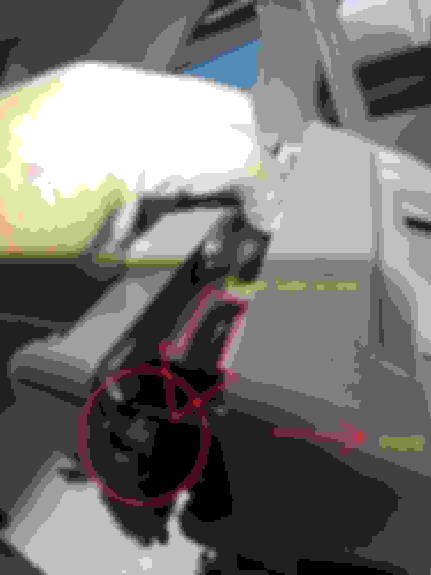
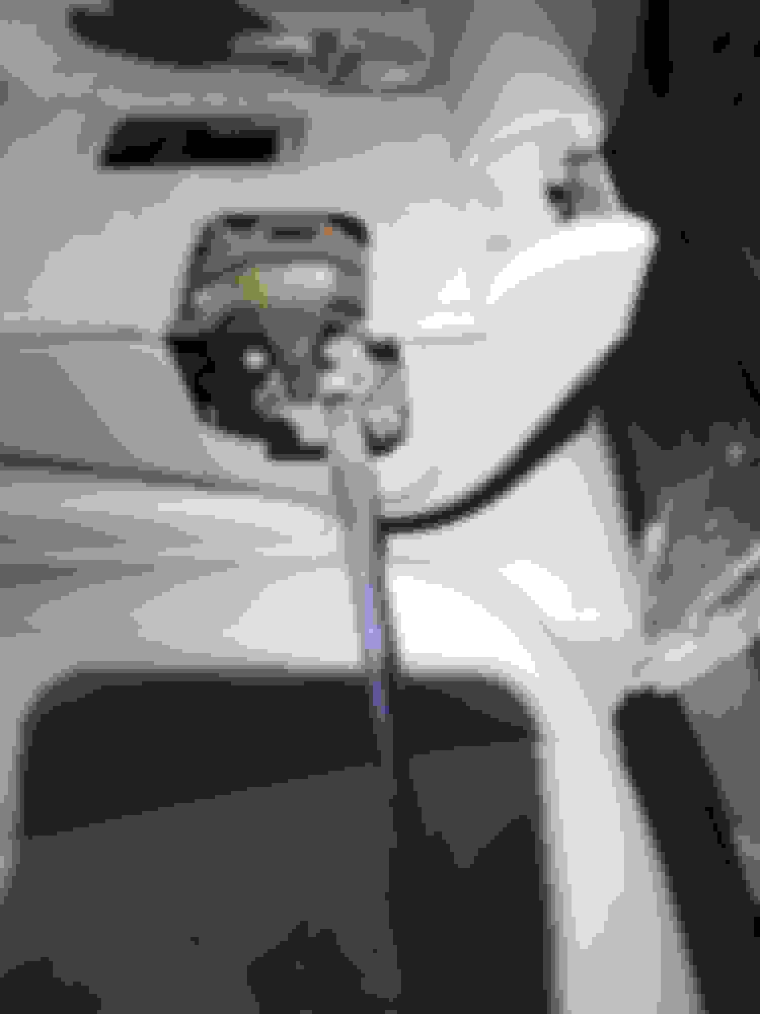
Pic 1 shows the back of the center seat in the down position. You can obviously see where the top plastic cover was. The main lever attaches to the cover and lifts up that L-Shaped rod you can see.
Seat Striker Cover:
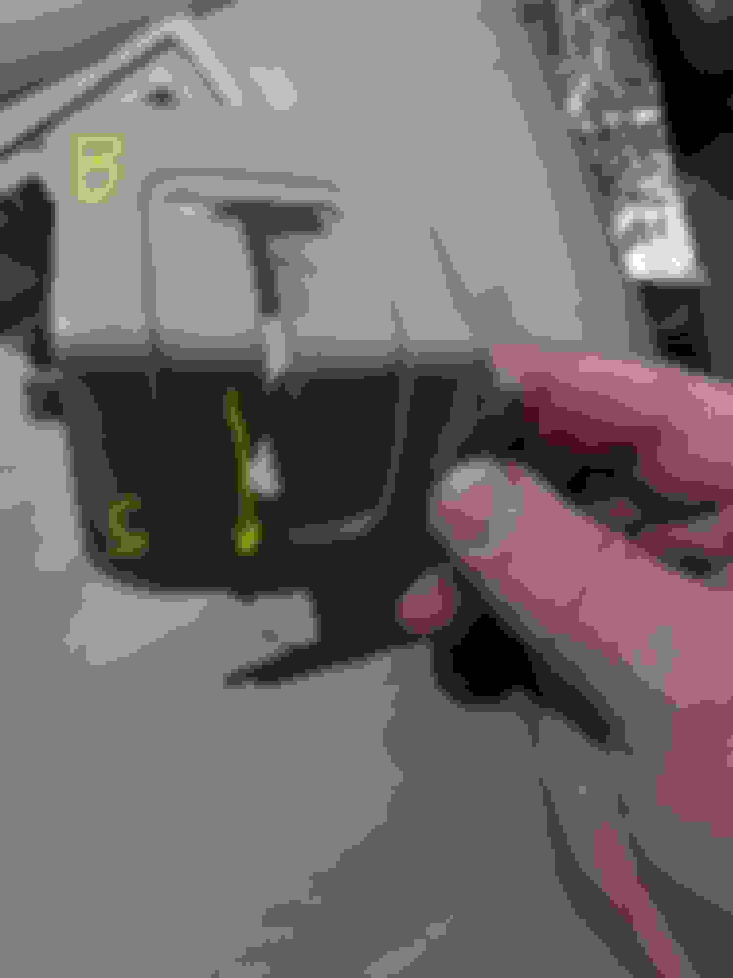
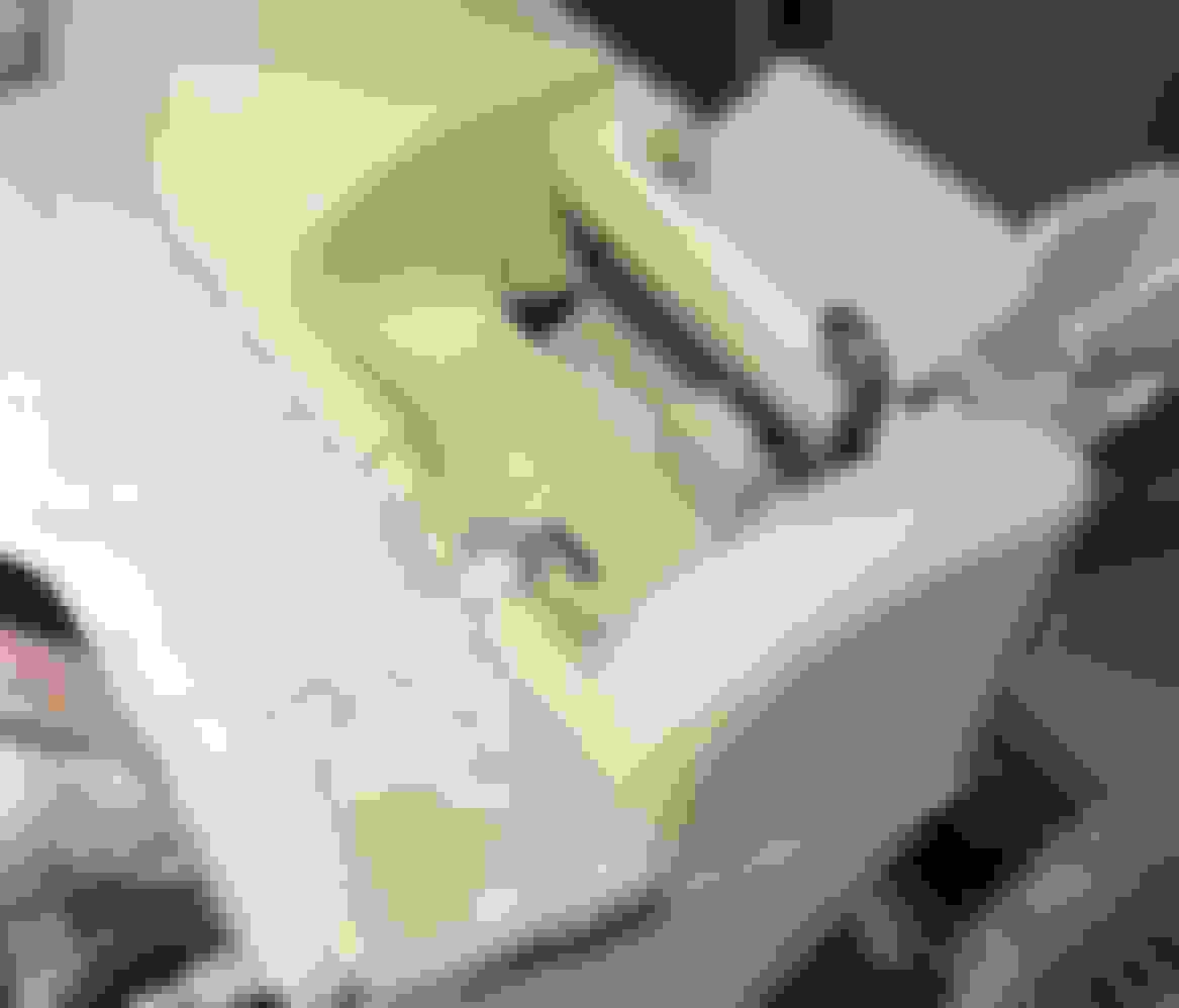
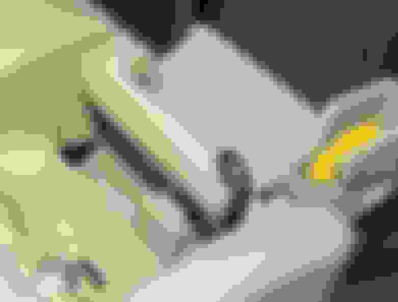
I’ve already removed the striker cover and the baby seat mount cover. Closest is the striker cover. To remove, you want to pull (or gently wedge using a screwdriver) the top (or rear) piece of the “L” toward the right side. There’s a tab that slides under the carpet cover. After you pull that over to release the tab, you can just lift the cover up and out of the side section. See pics 2a and 2b to see what it looks like underneath the striker cover. Pic 2b shows the position of the striker cover – B=back, S=Side. There are 3 big fat tabs on the Side of it so you have to slide that up and out after you unlatch the B tab.
Baby Seat Mount Cover
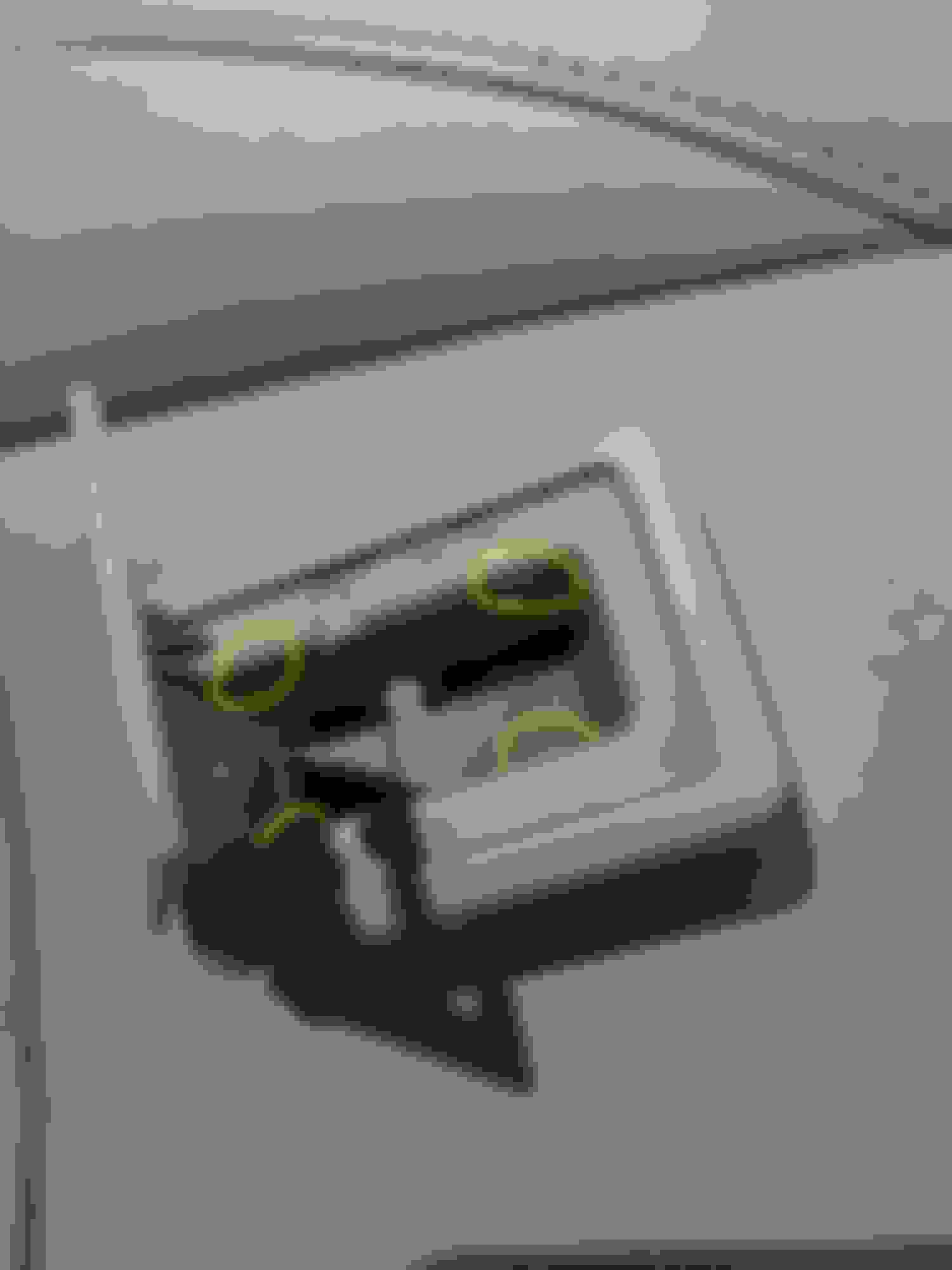
The baby seat mount cover is a bit easier. There are 4 tabs holding that one in, 2 on each side. I used 2 small flathead screwdrivers to gently pry back the tabs, one side at a time. If you have one of those small poker tools, that have a very small pointed end, that’d work too. See pic 3. It snaps onto the baby seat mount. I just lifted out one side after prying back the tabs, then worked on the other side and it just snapped right out. Yes, I cleaned that dirty thing before I re-installed.
Diagram of Back.
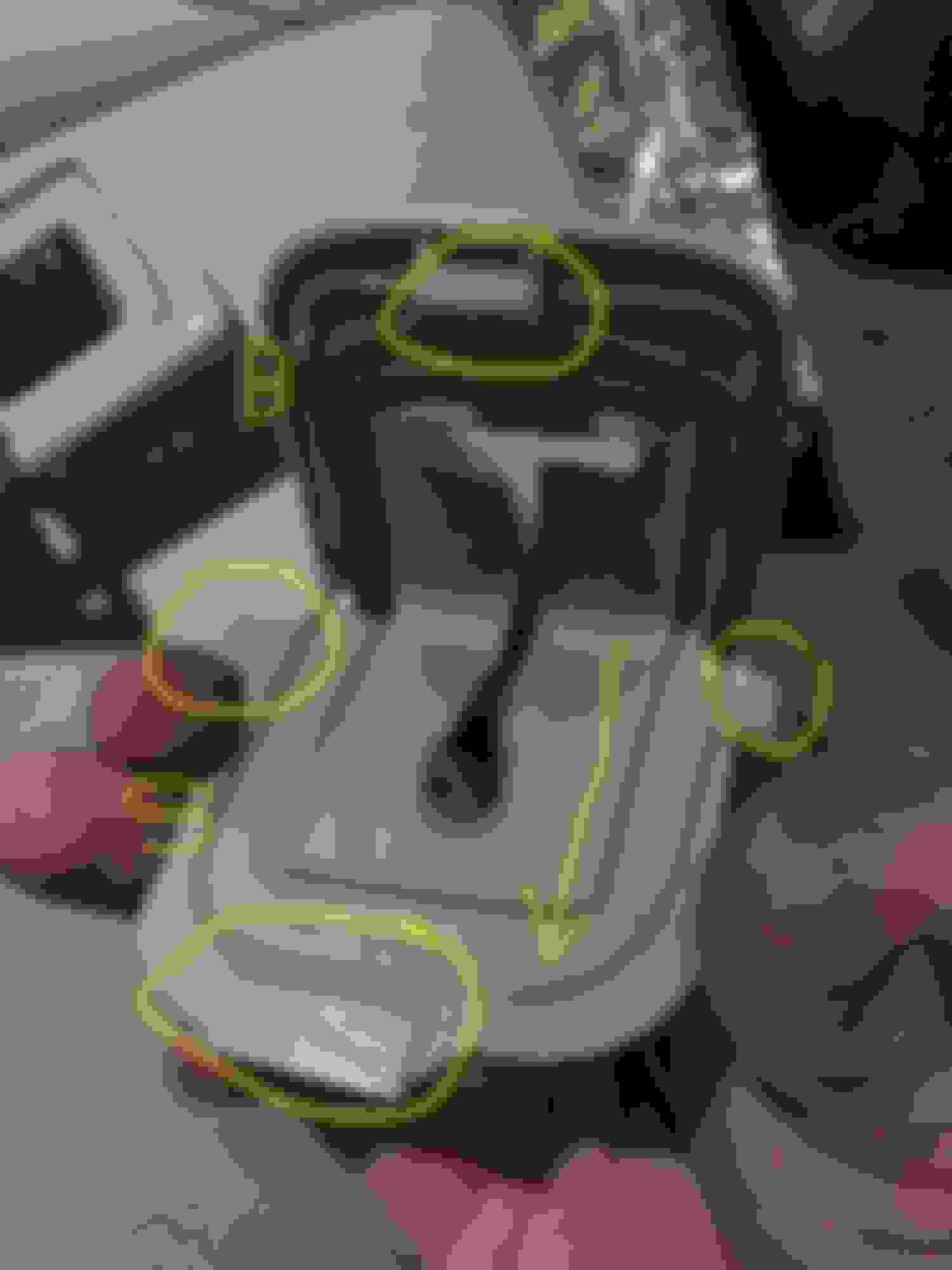
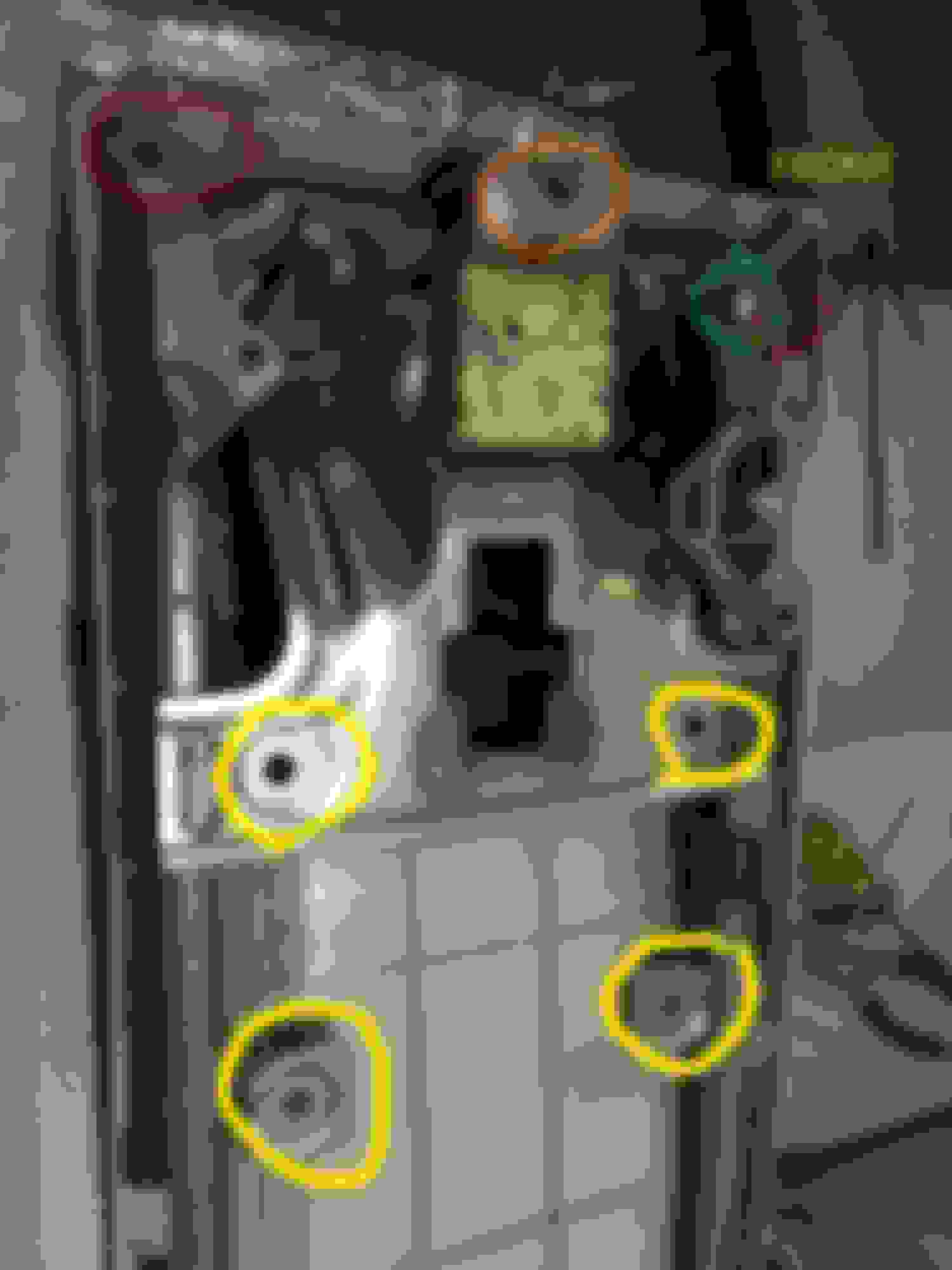
OK, now to the real stuff. Take a look at Pics 4 and 5. Pic 4 has circles around important areas. Pic 5 is where I line up the new Center Cover up to where it’s going to be installed to give you some reference regarding how the Center Cover is going to be mounted.
Pic 4 Yellow Circled Holes = This is where those white tabs, which are attached to the Carpet Back, attach to the main seat back. Sorry I don’t have a pic of the carpet back, but this shows you where they are. I have a tab removal tool, which is very handy, but it’s not long enough to reach inside there so I used one of those flat crowbars to get all the way under and gently pry up and out.
The top plastic cover obviously must be off at this time since the top cover will be installed over top of the upper (or front) edge of the carpet. If your top plastic cover is partially still installed, read on to see how to remove it when I install a new one. The entire carpet is attached to a big piece of that hard wood/cardboard pieces (similar material to the rear trunk covers that are covered in carpet) which hold the tabs. The white mounting tabs will be inserted into this quasi-wood material and are attached to these 4 holes.
The reason the back carpet cover must be removed is so you can have access to the inside of the center seat. This is necessary to pry the tabs holding in the Headrest Channels in order to remove the Headrest Channels. These Headrest channels need to be removed in order for the Seatback Cover (the bit piece of hard plastic opposite the Carpet cover) to be bent/moved in order to give you access to install the 2 side mounting screws in order to fasten the plastic Top Cover.
When you’re using your tool to lift up to pry off the carpet back, make sure to try to use the metal frame as a contact point so you don’t push into the big plastic lower (or front) part that the metal frame is mounted on. Just be patient here. If you pry up the carpet backing, you can look at it and see exactly where the 4 white tabs are so you can pry close to the tabs.
Pic 4 Red Circled Holes= These are the mysterious covered mounting points. See the far right for the 2nd red hole. These 2 screws are mounted through the front/bottom of the metal holes and are screwed into the 2 mounting holes into the Top Cover. The plastic top cover also has 2 female slots as seen in pic 5. Pic 5 shows how things are going to be linked up.
If you want to cheat and look ahead to help understand, look at pics 7b and 8. Pic 7b shows the Right Side screw attaching the metal base tab to the mounting hole of the Center Cover. Note the striker cover below this screw. Pic 8 shows the left side screw mount immediately before I installed the left side screw.
Pic 4 Green Circled Hole. This shows the normal looking mount that mounts from the rear. I have to remove the screw before mounting the top cover but left it in for reference.
Pic 4 Orange Circled Hole. I’m going to call this a “guide hole”. The top cover has a round tab that has to line up into this hole when you mount it. It creates some difficulty when you’re installing the top cover, but when this slides into the hole, you know that everything else will line up. See pic 5, Orange line, to see how/where it’s going to line up. This doesn’t have a screw and is just used to make sure everything will be lined up correctly.
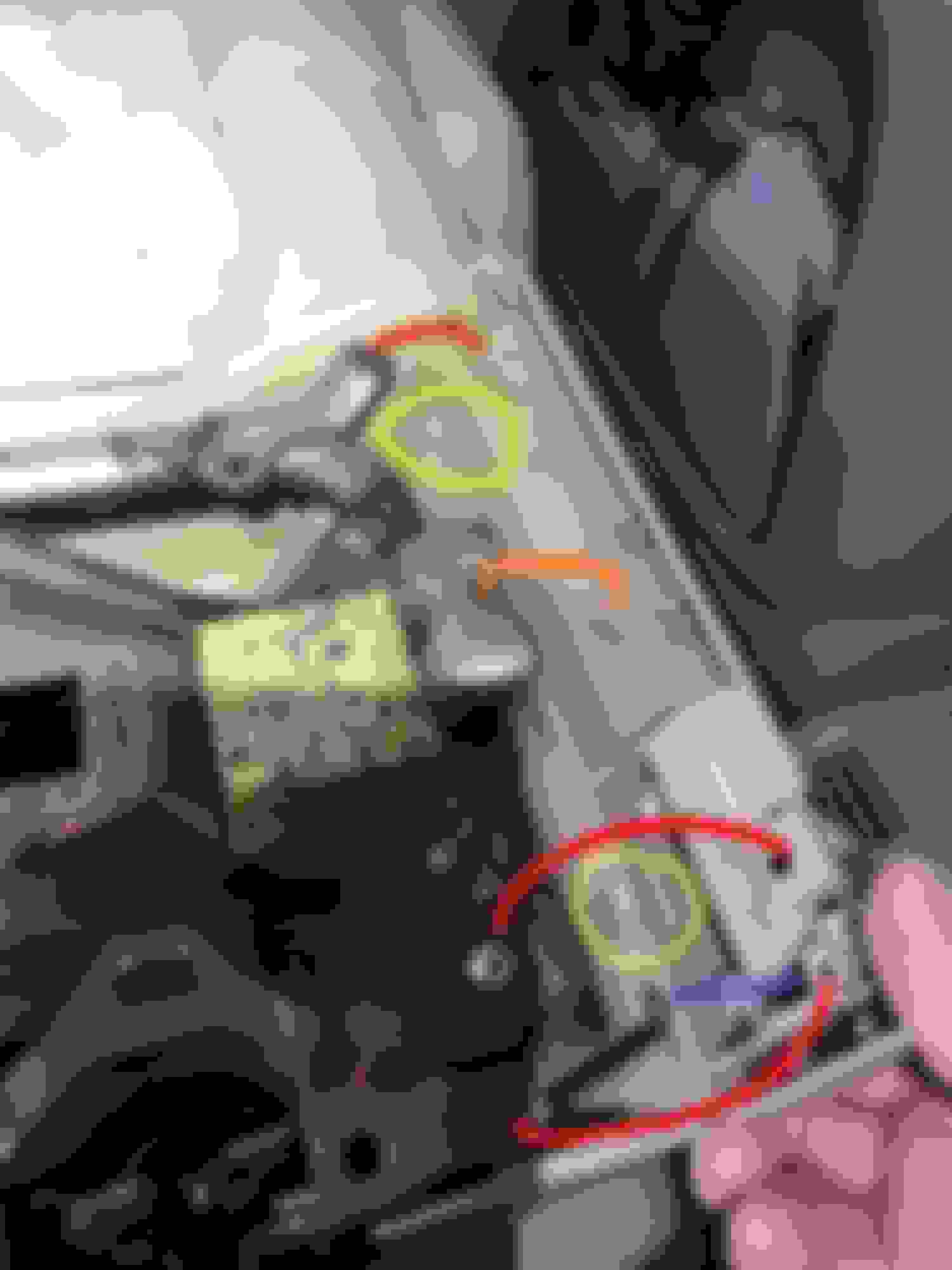
Pic 5 Top Cover Lineup.
Please see pic 5. I lined this up and got this pic so you could see the bottom of the Top Cover and how/where things are going to line up. Not mentioned yet about this pic are the tabs circled in Yellow and the rod near the blue mark that’s used by the Lever. The tabs snap onto the cover to stabilize it.
Pic 5 The Red circles indicate screws which fasten the cover to the metal frame base. The center red circled screw is installed just to make it easier for you to see it. This is an ‘easy’ screw to install and screws in from the rear. (assume center seat is in the up position). The outer circled screw holes , assuming the center seat is in the up position, screw in from the front, which will be a little work. The screw travels through the mounting hole in the metal frame base, then screws into the top cover, attaching the top cover to the metal frame base. I’ll get into detail about that later but pic 7b illustrates how this works.
Finally, the Pic 5 Orange line shows the ‘line-up’ pin on the top cover and the hole it goes into on the metal frame base. There’s nothing to attach here, but when you install, you have to make sure that ‘pin’ goes into the hole in the metal frame base. I think it’s there just to make sure everything is lined up exactly so all of the other attachment points will precisely fit. When doing the final fit of the cover, you have to move the cover a bit to make sure that pin goes into the hole. Until then, you can tell things aren’t going to fit perfectly. You just have to be patient and you’ll know when it gets lined up correctly because the top cover will fit perfectly onto the metal frame base.
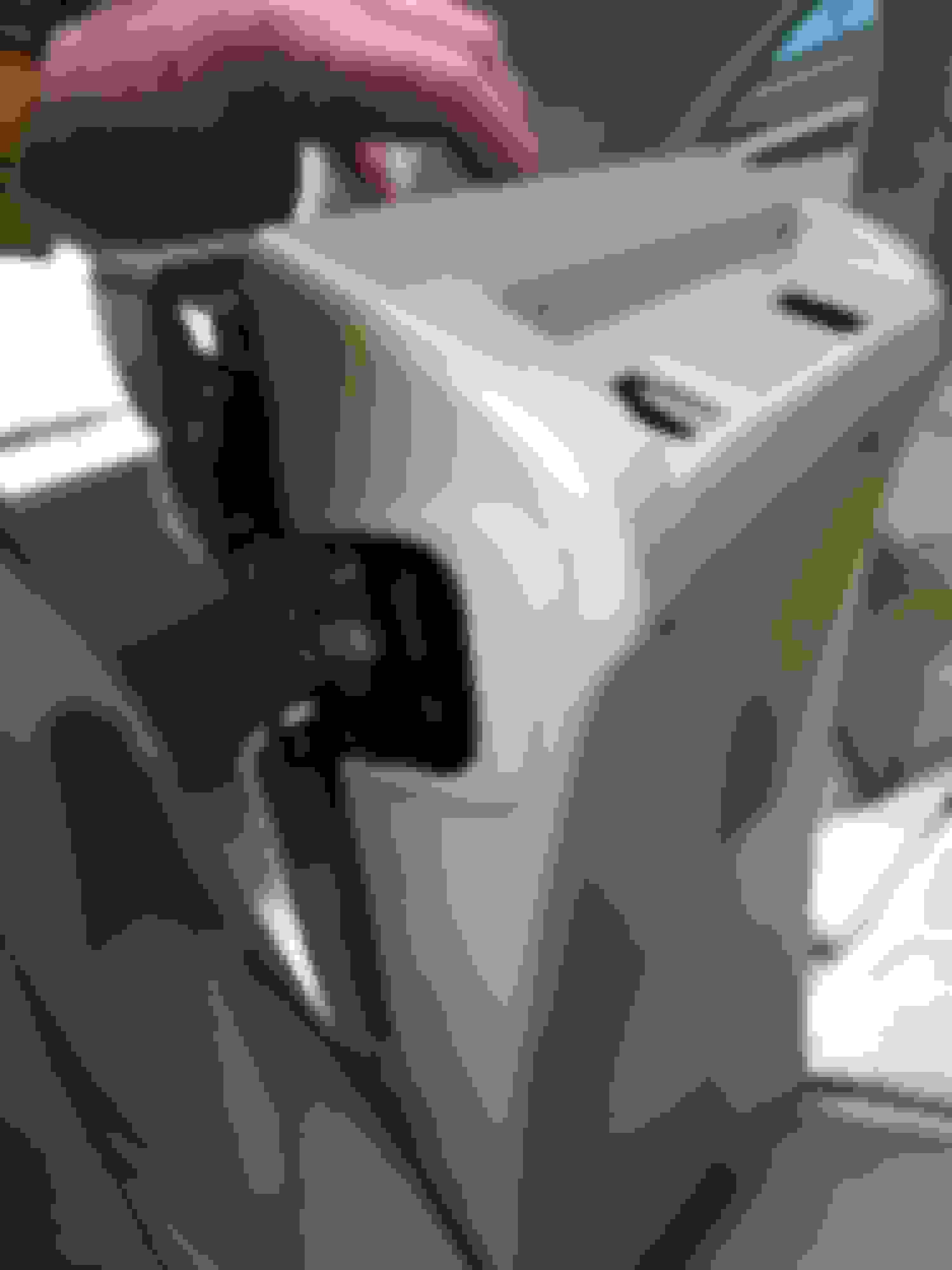
Next, remove the headrest from the center seat. There’s a tab on the top of the left side headrest Guide. Push in this tab, which is the adjusting tab, and lift the headrest completely up and out. Pic 6a shows the adjusting tab clearly.
Next we’re going to have to remove plastic the Headrest Guides. The reason is that the big plastic piece facing forward, or as the manual calls the “Seatback Cover”, needs to be opened a bit in order for us to insert those 2 outer screws which attach the Top Cover into the metal frame. See pic 6a which shows the Headrest Guides still installed through the Seatback Cover (the big plastic piece). As long as those Headrest Guides are there, we won’t be able to move the Seatback Cover at all.
Each of the 2 Headrest Guides are installed in a metal sleeve inside the center seat and have 2 tabs holding them in place. You must push the tabs inward and upward, while pulling up on the Headrest Guide. Surprisingly, this wasn’t as “nightmareish” as I though, although having an extra hand would’ve been nice. I just got a flat head screwdriver with a flashlight, pushed in (and up) the tabs while gently pulling up the Headrest Guides from the top. You don’t want to pull up on the top of the Headrest Guides too hard, or you won’t be able to push in the tabs. Pics 6b and 6c show the nasty tabs sticking out of the shaft before I pushed them in and slid them out. 6c shows the direction they go to remove them. 6d shows one out after I got the tabs pushed in successfully. 6e shows it fully removed.
Pic 7 shows the Headrest Guides completely removed. Note the “Seatback Cover” has some give now that the guides are gone. We need to use that ‘give’ in order to access and install the 2 screws which install the Top Cover to the metal Frame.
Congrats ! Only 3 more major steps to go. Hopefully you still have your wits and patience with you because you’re going to need them.
Next, install the Carpet backing. At this point, just line up the 4 tabs on the carpet backing wood frame piece that hopefully you didn’t break, and pop them in. This has the obviously be done before you move to the next step, which is installing the top cover.
Next step we’re going to be Installing the Top Cover onto the metal frame. Naturally, the main mounting points for the cover to the frame are the 3 screws; 1 is the normal easy screw , the other 2 on the ends as noted before are more challenging to screw in.
At this point, you may want to screw the 2 outer screws into the outer mounting holes of the top cover, then remove them. This should make it easier to screw them in later. I wish I’d done that, but you’ll know what I mean later.
Since you just removed the Headrest Guides, you probably noticed that since they’ve been removed, there’s some ‘play’ with being able to move the Seatback Cover, which is the big plastic piece which the Headrest Guides slid through before going onto their metal shafts. What you’re going to do is mount the Top Cover onto the metal Bracket. Take a look at pic 5 to see where everything’s going to line up. Again, make sure the “lineup pin” marked in orange slides into that hole in the metal base. It will take a few times, but you’ll be able to tell that it’s in.
At this point, go ahead and install the middle screw, that’s easy to access, and screws in from the top or the back depending on the position of the seat back. This should keep the top cover from moving around. Check to see that everything is lined up for the next part, the 2 outer screws that must be screwed in from the front. Look at all the pics marked 7 and 8 to see how it should line up. At this point, to screw the outer screws in, you’re going to have to bend the big plastic seat back away from the metal frame. This will give you room to insert the screw, then drive the screw in with a screwdriver, albeit at some degree of an angle. It may be difficult, but with some work and patience you can get the screws in. Use the longest Phillips head screwdriver you have if it makes it easier but be careful not to bend the plastic seat back too much since it’s still attached to the lower part of the seat. If you followed my tip above about pre-screwing the screws in, then removing, the outer screws ought to go in easier that if you hadn’t pre-screwed them in.
Next, go ahead and just pop in the big plastic seat back into the top cover you just attached. Note the 2 tabs on the top cover on pic 5 circled in yellow. See pic 9a. This is how the plastic seat back will attach to the top cover, now that the top cover is securely fastened to the metal framing via the 3 screws. 9b shows the 2 parts snapped together. Yes, I did have to remove the entire thing while I was working on this. I forgot what I did, but it was something stupid.
Now that you have the seat back cover snapped into the top cover, go ahead and slide the headrest guides back into their respective holes. You’ll hear and feel them snap into place as the tabs open up in the space in the bottom of their metal sleeves. This will completely secure the seat back cover back into place. Don’t install the headrest yet.
The next step of installing the plastic lever onto the metal tab was probably the most frustrating step, so if you’re ready for a break take it.
After trying different tactics of installing the lever onto the top cover before I installed the tab onto the lever and other contortions, I was finally able to make it work, but I’m not sure if Lexus’ assemblers did it this way.
As you know, the metal rod has to be lifted in order to release the seat-back rod from the Right Hand Seat if you want to lower the entire center seat. See pic 10a
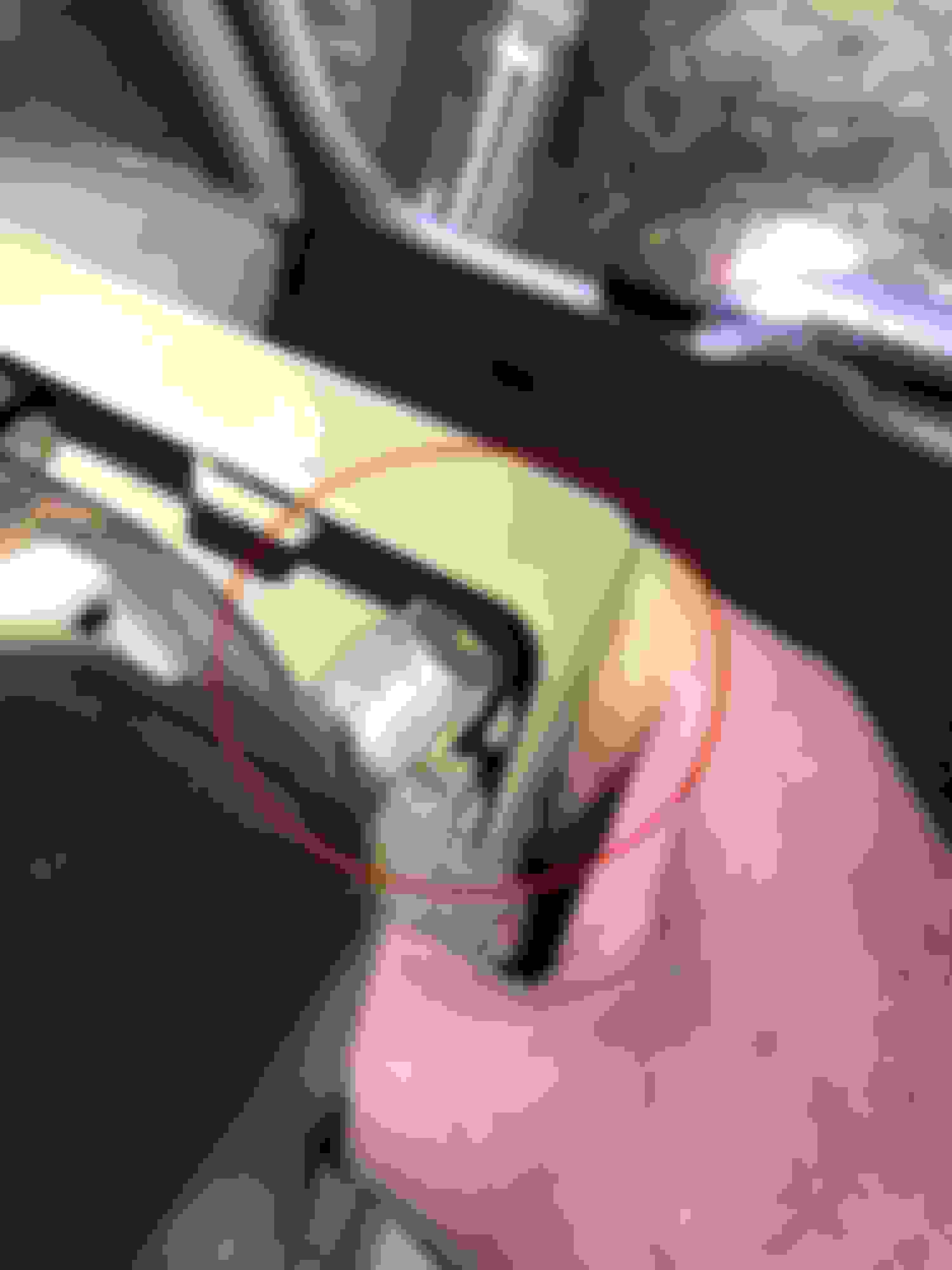
I found it near impossible to do anything without the metal rod in the highest position, but again, with 2 hands that was problematic while trying to install the lever onto the rod and the top cover. While pulling up on the metal rod with my hands (rather, a wrench), I noticed there was some sort of mechanism moving in the striker opening while I pulled on the lever. See pic 10b. I then figured what the heck so I pulled up in the metal rod as far as it’d go, then I stuck a flathead screwdriver (the widest one I had) into this mechanism and kept it there while I was trying to install the plastic lever. The screwdriver did the trick, but sometimes it liked to fall out so be ready to re-insert it.
Then I started ‘playing around’ with the plastic lever and the metal rod. The plastic lever is attached to the top cover via 2 tabs in the top cover. You have to insert the plastic lever into the center (Left hand) tab first, then in the lifted position of the lever, you can slide the other side of the lever into the Right hand Tab) Remember this for later.
Pics 10d showed my first attempts to put the rod into the plastic lever. I wasn’t making much progress so I tried to install the lever, then the metal rod. Pic 10e shows that that was going to be impossible.
I then concluded that I had to get the metal rod into the plastic lever somehow before I installed the lever to the top cover.
See pic 10f. The yellow indicates an area I’m going to call the rod lever channel, which is the space right on the outside of the hole the rod needs to go into, but inside that squiggly opening for who knows what. I was able to finally get the rod in by positioning the lever 90 degrees from the final installed position. This allowed me to put the rod into that channel and closer to the ‘target’ hole. What I mean by that is that the final position of the lever, as you know, is going to be parallel to Left-to-Right. To install the metal rod into the hole, I had the lever in a front-to-back position. Then I lined up the tip of the rod to the hole, then gently twisted the lever back to the final installed position, i.e. Left to Right, and the tip of the rod slid into the hole. I apologize if this seems confusing, but there’s no way I could get a pic of this. At this point of course, the plastic lever isn’t installed into the top cover. It takes a lot of jiggling and swearing, but I finally got the rod into the hole.
Pic 10g shows the rod finally installed into the lever.
Once I got the metal rod into the lever, I thought it was going to be easy after that. Nooooooo. I tried every method to get the lever installed into the top cover now that the Rod was attached to the lever, but nothing seemed to work.
Finally, with the Rod still installed in the Lever, I inserted/slid the plastic lever into the Left Side tab, then positioned the right of the lever on top of the Right Side Tab. Next, I pulled up on the lever as much as I could while making sure the right hole of the lever was positioned on the Right Side Tab. Finally, and ˝ out of frustration, I gently pushed down on the right side of the lever, and it just popped onto the Tab. It snapped right into it. I was expecting something to have been broken, but I guess that got it close enough to fit. Be careful not to BFH the lever and open it so much you break something, but pull it all the way up as far as it’ll go, making it get closer to easily sliding into the right side tab.
Sorry this is so wordy but this was a moderately challenging project and I wanted to share as much as I could.
The last pic shows the part numbers I used. I bought the Lever, the Top Cover, and the 2 outside screws which attach the top cover to the metal frame.
1 Back 2a Striker Cover 2b Striker Cover 3 Kiddie Seat Latch 4 Back with Carpet Cover Removed 5 Top Cover Holes Lined up 6a Headrest Guide 6b Headrest Guide Tab 6c Headrest Guide Tab 6d Headrest Guide Tab 6e Headrest Guide 7 Forward Plastic Cover 7a Moving forward Plastic Cover 7b RH Screw Attached To Cover Through Metal Frame Mount 8 LH Screw Hole before installing Screw 9a Ready to Snap Front and Top Covers Together using Tabs 9b After Snapping together 10a Before Lever Install 10b Holding Pin up 10c Struggling to insert Pin into Lever 10e This didn't work either 10f Rod/pin "Channel" (term I made up) 10g Rod Installed into Lever Finally 11 Final Lever Pic 11a Final
13 Part Numbers used. Top Cover, Lever, and Screws in first Comment.
Thanks ! I'd say in total, between 2-3 hours of real work on it because I was taking the pics and I didn't really know what I was doing. Also, the lever really stumped me for quite a while. I spent part of 2 days on it because I had a few drinks, other projects, and really didn't want to break the new parts I'd just purchased. I'm sure this won't come up often but it's kind of a weird area, i.e. seat, so I figured I'd document things.
 11-22-21, 10:29 AM