SC400 Fuel Pump ECU Check
 02-03-11, 09:06 PM
#1
Pole Position
Thread Starter
iTrader: (3)

Join Date: Jan 2011
Location: CA
Posts: 382
Likes: 0
Received 0 Likes
on
0 Posts
Need some help here. Engine runs great with the diag connector jumpered. According to everything on here, the ECU is bad. I don't really want to leave it jumpered. I would like to have it the way it was designed to operate.
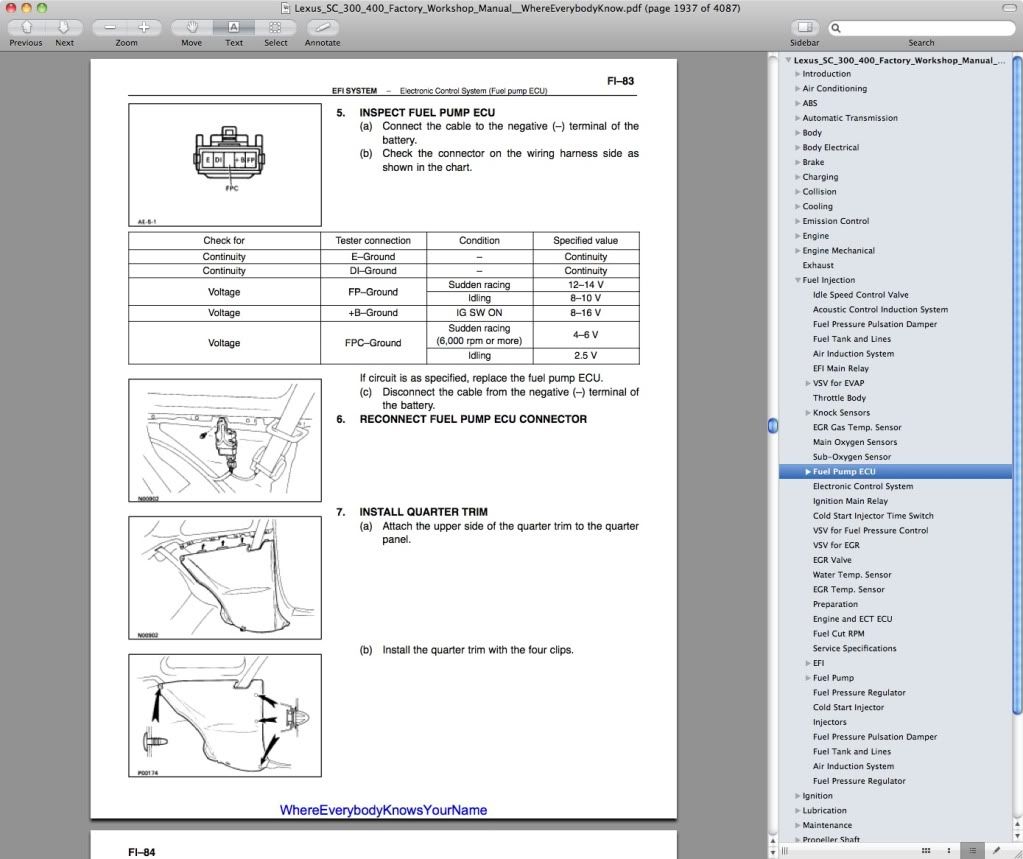
I am trying to decipher the FSM. I plugged the connector in and fired it up. using insulation piercing leads I checked the voltages on the appropriate wires and per the Lexus FSM on the fuel pump ECU, the voltage values were exactly what the book specified them, to be. However if you read below the table it says if circuit is as specified, replace the fuel pump ECU. Usually these manuals give you what you need to see. What this is telling me is that since I found the values to be as indicated in the table, I need to replace the ECU.
Does anyone concur?
I just want to ensure I dont have a lazy fuel pump.
 02-04-11, 04:05 PM
#2
Driver

Join Date: Jan 2011
Location: tx
Posts: 128
Likes: 0
Received 0 Likes
on
0 Posts
Yes, what it is telling you is that the main ECU is supplying 5V to the fuel pump ECU to indicate that it needs to run at high speed, but the Fuel ECU is not reacting to that signaling properly. If you have 5V at terminal FPC, it should be running at high output. With 5V at terminal FPC, what is voltage at the fuel pump? (all connectors connected normally)
-bug
-bug
02-04-11, 04:34 PM
#3
Pole Position
Thread Starter
iTrader: (3)
Join Date: Jan 2011
Location: CA
Posts: 382
Likes: 0
Received 0 Likes
on
0 Posts
Not really sure. I ended up bypassing the ECU to see how everything works. I checked the O2 sensors with the pump bypassed and I get normal voltage at 2500 RPM's on both, like 2.5V and the required number of fluctuations in 10sec. If I pulled the jumper and let the ECU take over the fluctuations are gone and I have 5V at the O2 terminals. So it seems like its saying hey, I need more fuel but the ECU is not kicking the pump speed up until I gun the engine, than the pump goes to high speed because I had no hesitation problems at high RPM's.
02-04-11, 04:50 PM
#4
Driver
Join Date: Jan 2011
Location: tx
Posts: 128
Likes: 0
Received 0 Likes
on
0 Posts
Hmm. If the main ECU is not signaling the Fuel ECU properly, it won't kick up the fuel pump. The fuel ECU looks to be a very simple beast. I suspect it is no more than a couple of power transistors or a small transistor/relay combo and perhaps a voltage divider, controlled by the main ECU.
02-04-11, 04:55 PM
#5
Pole Position
Thread Starter
iTrader: (3)
Join Date: Jan 2011
Location: CA
Posts: 382
Likes: 0
Received 0 Likes
on
0 Posts
I might suspect the main ECU except for the fsm guide on the voltages and conditions, than it saying that if I have those voltages I need to replace the ECU. To me the symptoms appear to be pointing t the ECU.
02-04-11, 05:09 PM
#7
Driver
Join Date: Jan 2011
Location: tx
Posts: 128
Likes: 0
Received 0 Likes
on
0 Posts
for the FSM are you looking at the step (5 in my copy) to "check the voltage between terminals FPC and E of the fuel pump ECU connector" ? and then if it is 4.5 - 5.5 V -> replace fuel pump ECU? If so, then yes, that check is showing that the main ECU is signaling the fuel pump ECU to provide full power to the fuel pump.
Trending Topics
02-04-11, 05:21 PM
#8
Pole Position
Thread Starter
iTrader: (3)
Join Date: Jan 2011
Location: CA
Posts: 382
Likes: 0
Received 0 Likes
on
0 Posts
I am using this chart in my FSM. I don't see what your referring to. The only time it tells me to measure FPC is to ground and I had the 4-6 volts with engine racing at 6k or more and like 2.4 volts when idling.
02-04-11, 05:23 PM
#9
Pole Position
Thread Starter
iTrader: (3)
Join Date: Jan 2011
Location: CA
Posts: 382
Likes: 0
Received 0 Likes
on
0 Posts
What I found interesting about this procedure is that they don't instruct you to start the engine, but how are you going to check voltages if the engine isn't running and the connector is off. So I plugged it in, started the engine and used insulation piercing leads for my meter and duplicated the described conditions for my readings.
02-04-11, 05:45 PM
#10
Driver
Join Date: Jan 2011
Location: tx
Posts: 128
Likes: 0
Received 0 Likes
on
0 Posts
I've got a different manual I guess. Your's looks much nicer! Same test though.
Where'd you get the pdf?
Basically what that page is doing is confirming that the fuel ECU is getting power and is also getting the proper signaling from the main ECU to switch the fuel pump from ~9V supply power <-> 12v supply power.
Where'd you get the pdf?
Basically what that page is doing is confirming that the fuel ECU is getting power and is also getting the proper signaling from the main ECU to switch the fuel pump from ~9V supply power <-> 12v supply power.

Thread
Thread Starter
Forum
Replies
Last Post
bugjug
SC- 1st Gen (1992-2000)
1
02-15-11 04:41 PM
acenase
Performance & Maintenance
9
04-16-09 04:15 AM