When you click on links to various merchants on this site and make a purchase, this can result in this site earning a commission. Affiliate programs and affiliations include, but are not limited to, the eBay Partner Network.
Hello, I have searched far and wide and have not been able to come up with an answer for this. I am trying to find a correct ECU pinout diagram for my USDM 1998 SC300 with VVTi. Seems that almost all information on this is for JDM cars, A80 Supra's or non VVT ECU's.
Wilboo's doesnt have the info in their z3x folder and none of the Toyota/Lexus forums do.
Wilbo's site is where I would have suggested to start but I see you've already looked there :/ I'm not sure that the 2JZ-GE VVT-i SC ECU has had its terminal pins confirmed into a pinout table yet.
Yes, thank you! This is exactly what I have been searching for. I just checked and my car is California emmissions. I wonder if there are any differences? Either way I only need the pins for the transmission so this should work great, thanks!
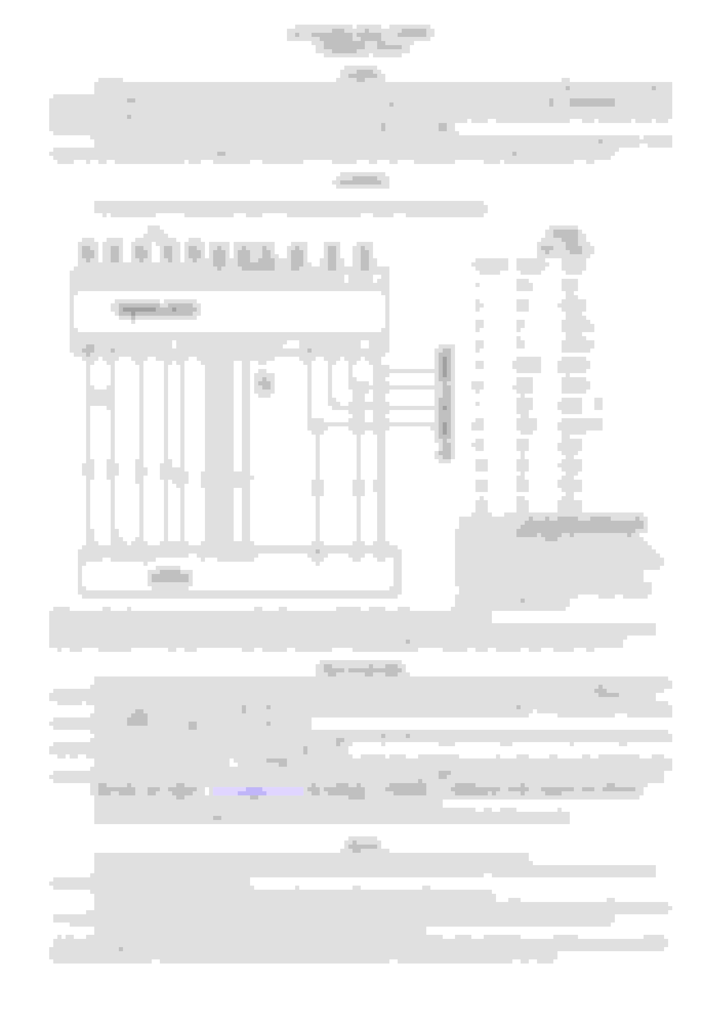
Okay actually I might have jumped the gun a little bit. It seems like some of the pins I am needed labeled on your diagrams. I am finding SP2+, SP2-, E1, NE+ , NE-, STP, and E1 which is all fine and dandy but I am still missing some pins. I attached the manual of the wiring diagram for the chip I am using. This is all a trial run to see if this chip, which claims to emulate the auto trans, actually works.
I still need to find all of the cables it tells me to cut, SLT+, SLT-, SLU+, SLU-, SLN+, SLN-, R, N, D, 4, 3, L, and NCO-
As well as the wires its asking to splice into which are missing from your diagrams: OIL, NCO+, 2, P, S1-4
I am assuming that most of the wires it is asking me to cut are from the auto transmission harness and as it points out in its instructions, it asks you to place a resistor between the + and - sides which is all fine and dandy I just need pinout for that plug.
This is the wiring manual for the chip that I am trying to splice in
You're welcome. I hope you're doing a build thread. I'm looking into an ECU swap for the 1UZ.
I'm assuming this chip simulates the transmission sensors and solenoids?
Yes, I have a build thread started on this forum. I will be adding more as soon as I start the actual swap after my winter term.
The chip is not actually supposed to replicate the solenoids themselves, as it notes in the instructions you replace the solenoids with resistors in between each wire. I believe it is supposed to help with the timing associated with VVT. It seems that doing a manual swap wiring the "old fashioned way" of bypassing the NSS and plugging in your solenoids still leaves the VVT at max retard in the higher part of the RPM range.
I am going to try to leave the solenoid wires uncut for the time being and plugging in the solenoids instead of the recommended resistors as thats basically what a solenoid is anyways.

 08-20-22, 04:41 PM