Quarter window mod part deux
#61
i have read your post i am just used to bmw diagrams. this is my first lexus and i am trying to be as careful as possible.
here is were i am stuck in the last pic of the completed relays. you have 2 blue and 2 yellow wires from relay one and 2 blue and 2 yellow 1 red and one yellow.
this is how i understand it.
.
now i know the black gets grounded
red goes to the package tray and you switch to 30amp fuse ( whats a package tray ) again no used to lexus.
one set of yellow and blue from no 1 relay gets spliced into the cpu 4 wires for both windows
and the other sets from relay 2 go to the switch.
tell me were i am wrong. sorry to take ure time but i just dont want to mess up
I am fairly good with mechanical things on cars but not so much the electrical/electronic stuff.
So, not wanting to fry my computer, I had mine done at my indie mechanic. You can Google 'The Toy Doctor' in Tualatin, OR and then contact them for some info.
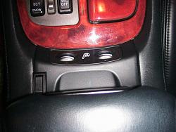
I used a switch that is a 'deadman' in that I have to hold it down in either direction to keep the windows moving. My switch is mounted right on top of the coin holder and looks like it belongs there.
If you would like a photo, contact me at:
jerrybaumchen(at)gmail(dot)com
Best of luck,
Jerry Baumchen
#62
Ok so i drew up a diagram quick of how i am understanding this. The one thing that confuses me is
1. When i get the switch what wire do i wire them up to?
2. Where do i get the positive power for the red wire.
-----------------------------------------
thank you
1. When i get the switch what wire do i wire them up to?
2. Where do i get the positive power for the red wire.
-----------------------------------------
thank you
#63
Many thanks to those who provided such detailed instructions that even I could easily do this mod. I put my "perfectionist" touches to this mod, but essentially followed their instructions:
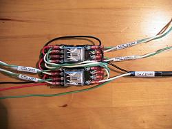
I assembled my relays and wires (I used spade connectors) before I ever touched the car:
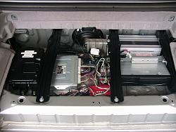
Here's what it looks like in the trunk:
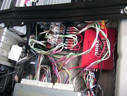
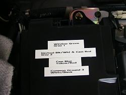
I labeled the wire colors so I'd know what I did later:
Final look:
Thanks for the great mod
I assembled my relays and wires (I used spade connectors) before I ever touched the car:

Here's what it looks like in the trunk:


I labeled the wire colors so I'd know what I did later:

Final look:

Thanks for the great mod

#65
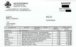
line 1: 20 feet of three wire to run from relays to the new switch (20 feet is more than enough, but I also used this same wire stripped individually to wire the relays)
line 2: 100 count male connectors (only need 4, used with line 6)
line 3: 100 count spade terminals (only need 32 to connect to relay sockets)
line 4: 25 count female connectors (only need 3 to connect to switch)
line 5: SPDT switch
line 6: 25 count self strip t-tap connectors (first time I've seen these, self taps into existing car wire without cutting or stripping and then provides a female tap that the above male connectors plug into) makes it real easy to unplug if ever a problem
line 7: 2 relays
line 8: 2 relay sockets
not listed on invoice (because I already had them): 8 count shrink-wrap butt splice connectors to connect new relay wires to existing car wires
Have fun,
Don
Last edited by donsmith; 07-24-11 at 05:05 PM.
#66
Many thanks to those who provided such detailed instructions that even I could easily do this mod. I put my "perfectionist" touches to this mod, but essentially followed their instructions:
I assembled my relays and wires (I used spade connectors) before I ever touched the car:
Attachment 217148
Here's what it looks like in the trunk:
Attachment 217149
Attachment 217150
I labeled the wire colors so I'd know what I did later:
Attachment 217151
Final look:
Attachment 217152
Thanks for the great mod

Thanks for the info on uploading photos; now let's see how it goes.

If all goes well, here is a photo of my switch & its location.
I like it a lot and (yes, I'm biased) think that it looks sorta 'stock' or as if it belongs there.
Jerry Baumchen
The following users liked this post:
Eathon (12-08-20)
#67
After carefully reading (over and over) Lexiss SC430’s instructions, I came up with what I believe is the “long awaited” wiring diagram for the quarter window mod.

To all that have performed this mod, please feel free to verify and confirm the accuracy of this diagram.
Thanks Lexiss SC430 for the detailed instructions.
Download the PDF for clearer image.
NOTE: The switch must be a "Momentary on-off-on" type.

To all that have performed this mod, please feel free to verify and confirm the accuracy of this diagram.
Thanks Lexiss SC430 for the detailed instructions.
Download the PDF for clearer image.
NOTE: The switch must be a "Momentary on-off-on" type.
Last edited by scyul; 07-26-11 at 07:44 PM.
#68
After carefully reading (over and over) Lexiss SC430’s instructions, I came up with what I believe is the “long awaited” wiring diagram for the quarter window mod.

To all that have performed this mod, please feel free to verify and confirm the accuracy of this diagram.
Thanks Lexiss SC430 for the detailed instructions.
Download the PDF for clearer image.
NOTE: The switch must be a "Momentary on-off-on" type.

To all that have performed this mod, please feel free to verify and confirm the accuracy of this diagram.
Thanks Lexiss SC430 for the detailed instructions.
Download the PDF for clearer image.
NOTE: The switch must be a "Momentary on-off-on" type.
After looking at that diagram here & in the other thread is why I had mine done.

Jerry Baumchen
#70
Well... It's done... Finally!
After thinking about it for a long time, I completed the project today. And it works great!
Followed exactly the schematic I drew. The ground is attached to one of the stud/nut in the trunk, and I took the 12v (switched) from the cigarette lighter wire in the center console. I installed the switch next to the trunk/gaz door buttons...
Last edited by scyul; 09-03-11 at 02:07 PM.
Thread
Thread Starter
Forum
Replies
Last Post
Five1OH
GS - 1st Gen (1993-1997)
1
04-04-09 12:54 AM


