When you click on links to various merchants on this site and make a purchase, this can result in this site earning a commission. Affiliate programs and affiliations include, but are not limited to, the eBay Partner Network.
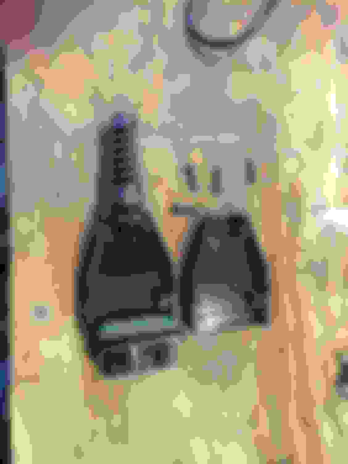
I am posting this picture again to clarify where you need to solder.
see the row of holes in the Center...it�s circled in yellow.
i soldered the two holes together, they are connected to pins 4&14.
I bought the ebay connector and it looks identical to the connector in the picture. Looking at how it is wired on the board I see how pin 14 is connected on the board to center row pin 2, and I see how pin 4 is connected to center row pin 3 but it also looks like pin 4 is bridged to pin 5 so that both pin 4 and pin 5 are connected on the board to center row pin 3. So when I solder center row pin 2 to center row pin 3 it will connect (short) pin 14 to pin 4 and to pin 5. Is having pin 5 also connected to pin 14 and 4 a problem? Should I cut through the bridge circuit that connects pin 4 and pin 5 or is it not an issue or am I reading this connect board incorrectly - or maybe I have wrong connector?
I bought the ebay connector and it looks identical to the connector in the picture. Looking at how it is wired on the board I see how pin 14 is connected on the board to center row pin 2, and I see how pin 4 is connected to center row pin 3 but it also looks like pin 4 is bridged to pin 5 so that both pin 4 and pin 5 are connected on the board to center row pin 3. So when I solder center row pin 2 to center row pin 3 it will connect (short) pin 14 to pin 4 and to pin 5. Is having pin 5 also connected to pin 14 and 4 a problem? Should I cut through the bridge circuit that connects pin 4 and pin 5 or is it not an issue or am I reading this connect board incorrectly - or maybe I have wrong connector?
Pins 4&5 are both ground. All OBD connectors should be the same.
First post after years of lurking.
I also had this problem. Of course, nobody at dealerships could tell me why my sc vsc/off lights wouldn't clear.
Finally, found this. Used holes 3 from left top, 5 from the left bottom with a paper clip. DONE.
So happy and many thanks Club Lexus.
1. Turn off ignition.
2. Look for the OBD-II connector under the dash, it has a black plastic cover which can be pulled out.
3. Use the re-set tool, plug it in on the OBDII connector.
4. Turn ON the ignition, do not start.
5. VSC and Check Engine lights turn ON. That's normal.
6. Wait for the VSC light to rapidly flash.
7. Turn OFF ignition.
8. Pull jumper wire out, cover the OBD-II connector.
9. Turn ignition ON, don't start, wait about 15 seconds to make sure everything has initialized.
10. Start car. Test drive.
The pins below are the ones you need to short out.
Mandyfig or Bgw70....will this procedure work on a 2006 Lexus SC 430 too??? I'll be using two paper clips on pins 4 & 14. Thanks!!!
1. Turn off ignition.
2. Look for the OBD-II connector under the dash, it has a black plastic cover which can be pulled out.
3. Use the re-set tool, plug it in on the OBDII connector or use a paper clip and short pins 4&14
4. Turn ON the ignition, do not start.
5. VSC and Check Engine lights turn ON. That's normal.
6. Wait for the VSC light to rapidly flash.
7. Turn OFF ignition.
8. Pull jumper wire out, cover the OBD-II connector.
9. Turn ignition ON, don't start, wait about 15 seconds to make sure everything has initialized.
10. Start car. Test drive.
The pins below (4&14) are the ones you need to short out.
My Scangage II is permanently mounted on the SC, I want to know the Intake Air temperature, as I have my intake cone inside the engine bay. One day I will re-route the intake to the bottom, so it picks up cold air. Anybody has a set up with the intake picking up cold air? I think the only way is to cut sheet metal and that's hard to do.
My intake cone is also located in the engine bay.
What kind of temps are you seeing?
Originally Posted by mandyfig
My Scangage II is permanently mounted on the SC, I want to know the Intake Air temperature, as I have my intake cone inside the engine bay. One day I will re-route the intake to the bottom, so it picks up cold air. Anybody has a set up with the intake picking up cold air? I think the only way is to cut sheet metal and that's hard to do.
I have been using a Die Hard Battery Charger/Maintainer on the SC and most recently, I had a CEL and VSC lights on. I cleared the CEL with my OBD tool and then pulled my VSC Rest device, plug and play. Lights gone. So happy to have this neat little tool.
I now have an easy to use VSC OFF light reset tool.
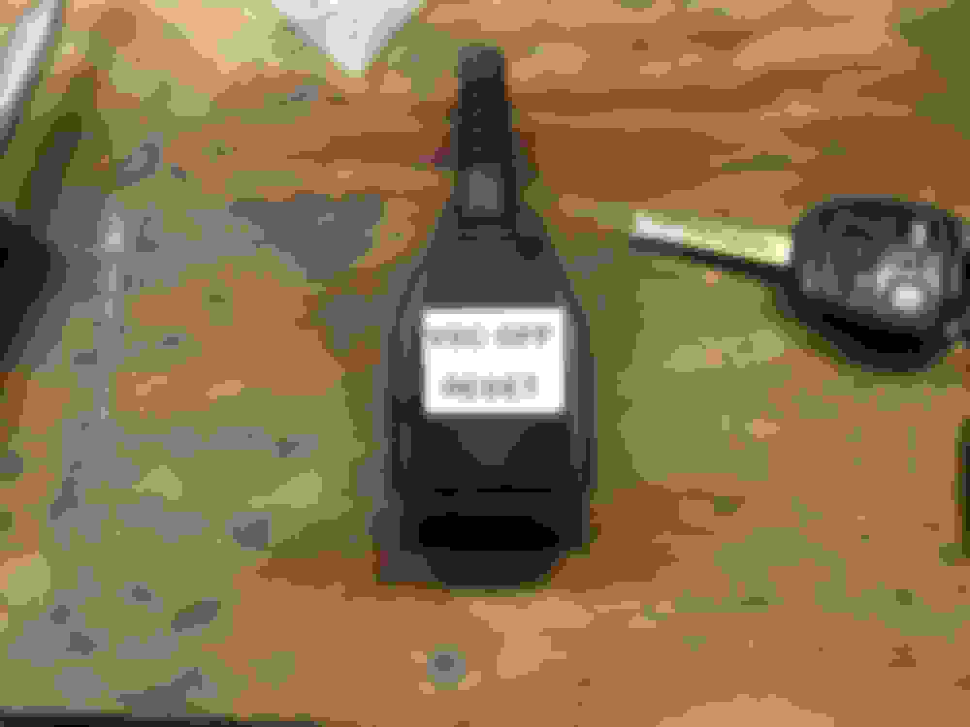
Here is the $2.10 OBDII connector purchased on eBay from a guy in China. It took about two weeks for it to show up.
If you look at the center row you will see the jumper I soldered between the two points toward the bottom of the connector. Those two points are connected to pins 4&14.
The finished product. Very easy to build and use.
Awesome. I just made the tool. It is so nice to have some smart guys to refer to for maintaining the SC. When I soldered the 4 and 14 I did a continuity check with all the pins and noticed 4 and 5 were also internally connected together. To play it safe I cut off the number 5 pin so as not to cause any unwanted shorts. It must be ok, though since no one reported any problems.
Thanks again. I have over 200k miles and trying to milk this car to the end. (-:
The prices are up to $3.55 for the male OBDII plug on Ebay now!
Question: For $8.00, one can get the same male connector with a short extension to a female connector. With this one, a person could simply insert a bus wire between the 4 and 14 pins on the female end and get the same results, right? Plus, there may be other uses for it as one could remove the reset bus.

 01-15-18 | 04:18 PM