When you click on links to various merchants on this site and make a purchase, this can result in this site earning a commission. Affiliate programs and affiliations include, but are not limited to, the eBay Partner Network.
Cigarette lighter charge. I have seen someone did it before. If you could provide a guideline, that would be great.
For most of the hacks you did, surely you had to disconnect the terminals to the battery, right?
I will be sure to take some pictures and write up some detail when I get back in there. I am swapping out the charger I already installed with another that also has an aux input. I also plan to re-do the light.
No, for the mods above, I just removed the modules and brought them in to my workshop where all my soldering equipment is. I can test everything on the bench also.
I've made quite a bit of progress already converting the IEBus controller code over to Arduino. I have also come up with some add-on features I have started fleshing out.
One of the goals is to allow these to act like a standalone "device" as if it were OEM. Then the firmware can be loaded on to an Arduino mini, nano, or micro and act like new ECUs in the car. For example, the neopixel lighting will be on one of these nodes.
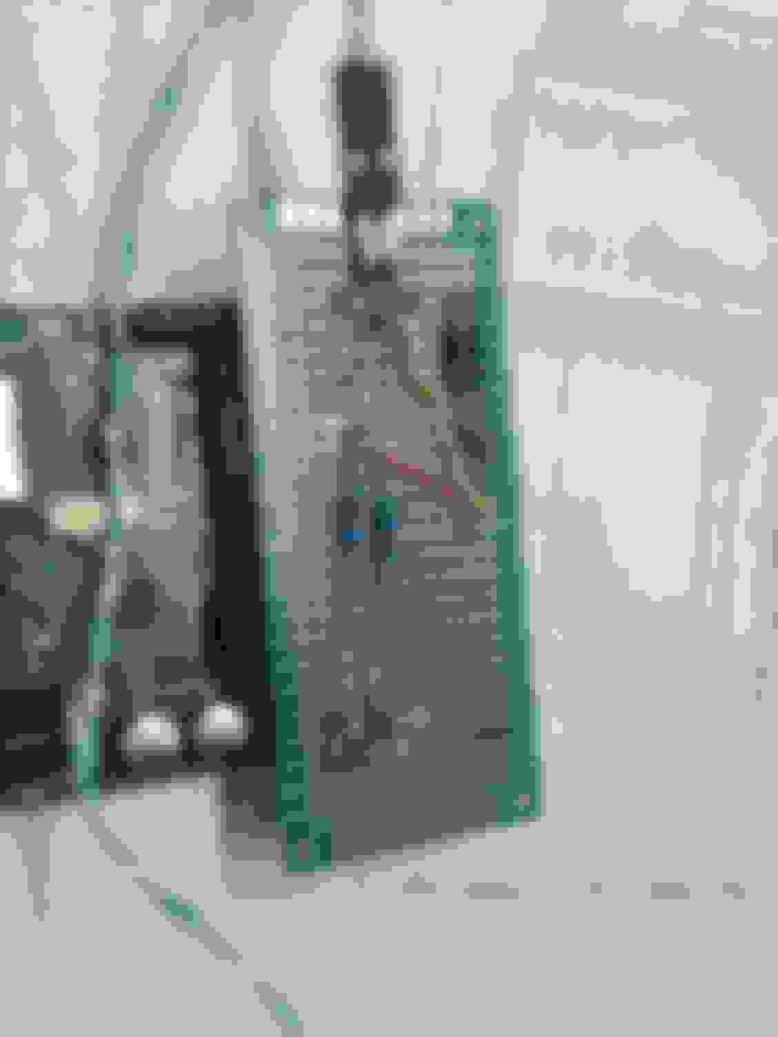
I jigged up the NAVI unit for doing some reverse engineering. Since I don't have the factory harnesses for it, I fashioned up some of my own. I crimped wire on to some butt-connectors, removed the excess insulation and carefully pinched the other end to make it flat. This pushes on securely to the pins on the power connector. In one case, two of the pins right next to each other needed the same signal and a spade connector fit perfectly across them both. I can now power up the Navi on the bench.
The other pins are small enough that I just used female jumper wires and plugged them in.
It's going to take some time to trace out the circuit internally, so details of that will need to wait a while. My end goal is to replace the screen with a higher resolution LCD with HDMI, VGA, and 2 composite inputs. I want to keep the controller board which controls the touchscreen and LCD. To do that, I need to determine how the system controls the OEM LCD controller over the 30 pin flex cable and emulate it.
I will be sure to take some pictures and write up some detail when I get back in there. I am swapping out the charger I already installed with another that also has an aux input. I also plan to re-do the light.
No, for the mods above, I just removed the modules and brought them in to my workshop where all my soldering equipment is. I can test everything on the bench also.
I highly appreciate it. I will experiment it on my other cars first before trying it on the SC. Thanks.
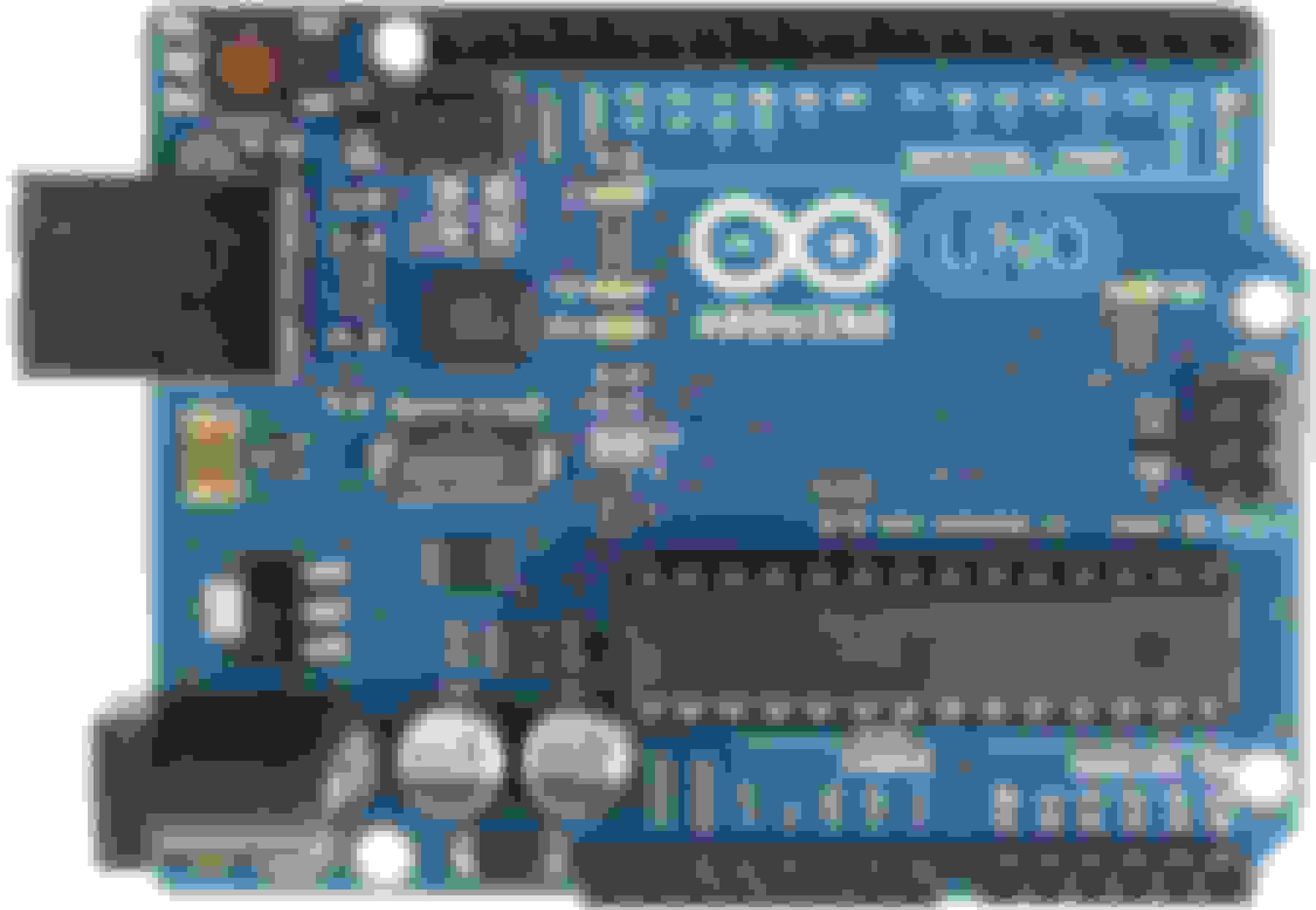
So here is the basic circuit using an Arduino Uno R3 microcontroller board. This is a simple conversion of the hardware from Angry Camel's design. The relays were removed since they weren't yet used in his code anyway. The Activity LED was replaced with the on-board LED of the Uno, reducing parts needed.
IEBus Controller using an Arduino Uno R3 with an ATMega8 running at 16Mhz.
The benefit here is that you can use an Arduino board and don't need to make your own board. This also gives you a USB serial connection to your computer. The parts required have been greatly reduced and simplified.
I have converted the code to run on the Arduino board at the 16Mhz (still need to test this in car) but it still needs the ATMega8. This means getting an Arduino with a DIP socket and swapping out the micro and also getting a programmer.
Until I completely port over to Arduino code which is not device specific, the ATMEGA8 is required and will need to be programmed with an ISP programmer. But this will be the first version and I can get it slapped together this weekend to play with.
So, this is not yet friendly to those without some extra equipment and knowledge. But I wanted to share it as an example of how few easy to find components are required. It doesn't look nearly as intimidating this way.
This works by using separate pins for the transmit and receive portions. the D2 and D3 lines are the driver lines (transmitter) and the D6 and D7 (Built in Analog comparator) for the receive lines. This piece is important because it allows to connect to the differential signal of the IEBus. The specific diodes used in the driver section are not particularly important, but they should be high speed diodes (signal diodes.) The resistors provide a voltage divider to drop the signals to the levels used on the IEBus and to provide the impedence needed by the bus. Nerdy talk, but not absolutely necessary for you to understand.
I am presenting this, because I needed a baseline set of hardware to test against my full port over to Arduino. Much easier to debug if you have something working. So, I am expecting that this weekend I will have this hooked up to the car to try out.
If all of this makes your head spin, just hang in there and something is coming which will be much more friendly to non-geeks. At this point, if you are not familiar with these topics, much of this won't make a lot of sense.
Again, all of this is based off Angry Camel's design and software, so I want to make sure he gets credit although I found no way to contact him to get permission, he stated on his site that he no longer had the time to work on this and was offering it up for others to take over. I take that as permission. By the time I have this completely ported over to Arduino, it will basically end up being all my own code, anyway.
Basically it is a development board that provides a USB serial port for uploading code without needing any special equipment. And after the code is running, it becomes a serial port to easily talk to it with a computer. The Arduino programming environment also removes device dependency so the code you create becomes very portable to other microcontrollers. Once this is fully ported over, all you will need to do is pick up one of these boards and connect up the few extra components in the drawing above. The you will open the code I provide in the Arduino software and press upload. And like magic, you are up and running. It (will be) that simple.
In this first design, I am only taking advantage of the pre-built board and the built in USB serial port. It is not plug and play yet like the full Arduino environment.
I realized that some may have an even more basic question: what is the purpose? Well, this will allow you to talk to just about any device in the car. This allows you to either use the built in controls like steering wheel, head unit, or navi controls to control your devices or software on a computer. Or you can be the master and control things like switching to CD1 for an aux audio in, displaying text on the radio screen or heater display, etc...
You can do things like turning the navi touchscreen into a mouse for a computer or turning your radio into an MP3 player allowing you to use the standard radio and stereo controls to control MP3 playback. It would also allow you to display which MP3 is playing on your radio.
This is the little magic box that all those expensive gadgets use to integrate things like the aux video and audio into your car.
You can control or be controlled by just about any device in the car. The only real limitation is the complexity of the code, of course.
LoL, I sure wish you were here six months ago!!!
You are incredible and I am really enjoying your knowledge you are sharing with us!
BTW, look up the TechStream software when you have a chance. Several of us have it. It is the Toyota diagnostics/control software.
I've seen it but the details on it are very limited. What does it provide? It also looks like it needs a professional technician subscription to TIS to use it?
Are there any manuals for it I can look at to see if I would like to purchase it?
EDIT: After doing a bit of reading, I ordered this:
$34.17 for two day shipping and according to what I am reading, comes with an unlocked version of Techstream and has all the same features as the "official" version. Looks like it can be used to change some things like time of key chime, etc... Sounded useful.
Just to be clear, this won't do the same thing as the IEBus controller.
Please keep post pictures we can track your progress!
I love your plans! keep it up
Will do. Things may go slow sometimes with work and RL involved. Not to mention the terrible wait for parts. I try to keep a few projects going at once so the wait for parts is not too unbearable.
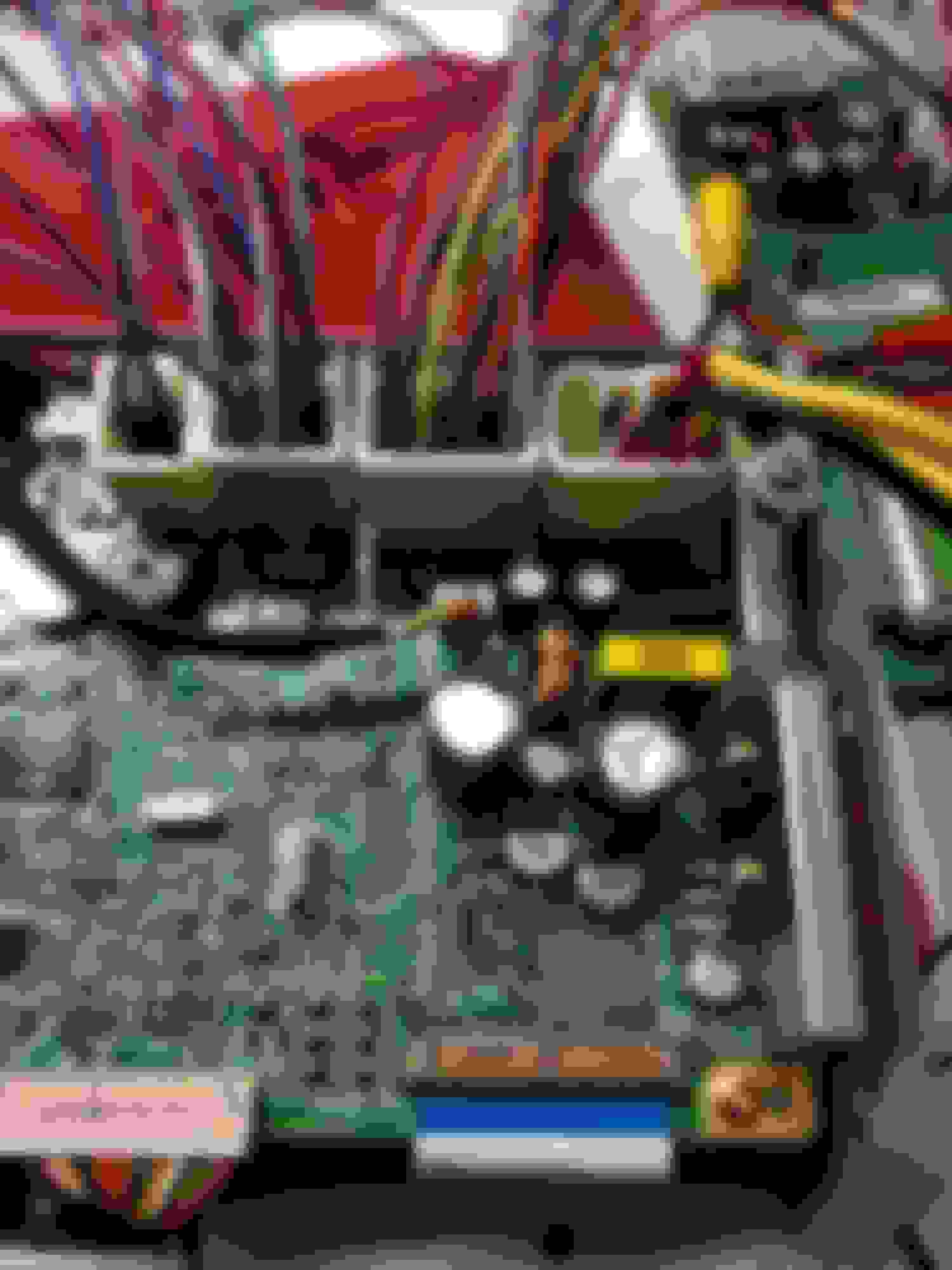
So I managed to find a little time tonight to whip together the IEBus controller circuit. Just a quick toss together, so it is certainly not my best work and won't be the final polished unit. But hopefully it will get me through developing and debugging the code. Once I am satisfied it is working correctly, I will have a board made up and a nice enclosure for it.
There is a 3 or 4 pin connector inside my center console running by the shifter that was plugged into a blank on the bottom of the cup-holder assembly. I cannot identify it on any of the wiring diagrams. Anyone have any idea? I am hoping it has the IEBus signals on it. This area would be a really nice place to mount my box.
BGW70 any chance you can identify it since you have the full service manual?
Man oh man I am digging this post. I am intrigued by all of this! So, technically, you could use this Arduino to interface with a wireless module to essentially create a Luxlink where you could remotely start the car or open and close the top...theoretically, correct?
Man oh man I am digging this post. I am intrigued by all of this! So, technically, you could use this Arduino to interface with a wireless module to essentially create a Luxlink where you could remotely start the car or open and close the top...theoretically, correct?
I am not positive yet, but I don't think you would be able to start the car over the IEBus. I believe it is reserved for instrumentation, audio, video, and controls. As such, I don't think it does anything without the car at least in acc mode to turn on all the ECUs.
Once I get it connected in the car, I can poll for what devices are on the bus. After that, I can figure out what commands are available.
Angry Camel made some awesome software for his original design called IEBus studio which allows you to watch the messages going around the bus, set filters, playback commands to see what they do, etc.. This really opens up the world of possibilities.
That is why I am working with his design. I found a way to email him to ask for the source to IEBus studio to continue development on it, but no response as of yet. For now, I only have the source code for the micro-controller.
Hit a brick wall with this code last night, I hope to get sorted out this weekend. I am pretty sure AngryCamel didn't put up his latest code. I can't see how this code would have worked. Right out of the gate, I got tons of compile errors. After I fixed those, the micro just keeps resetting. I can see where in the code it is happening, but it would have had to have done that for him as well.
I have been practically rewriting everything, anyway. I guess one advantage to that is that I am getting a much better understanding of how it works which means I can finish up some of the features he had in mind, expand on features, and add some error trapping in there to make it much more stable.
The good news is that it really doesn't matter how the micro does what it does as long as it outputs data that is compatible with his IEBus Studio program - which I plan to re-write as well since I don't expect to hear from him with the source code for it.
Not a huge roadblock, but I am going to need to sit down with a pen and paper and work it all out.
I'd say I have about 85% of it set up on the arduino already. It's just that last 15% is stumping me at the moment.
Retroplay, a couple of comments on your (minor) issues:
>> The map lights do have the positive and negative terminals reversed. Why? I don't know. It didn't make sense to me either but rewiring the mirror/light mount looked like a pain to me. So I wound up finding a guy on ebay who sells BA9 LEDs and matched up the Lumens ratings to an incandescent. The best part of the story is that he would sell the LEDs with reverse polarity. So I bought those. They look great.
>> The connector plugged into the dummy connector was for a car phone feature.

 09-09-15, 02:58 PM


 By the time I have this completely ported over to Arduino, it will basically end up being all my own code, anyway.


 I try to keep a few projects going at once so the wait for parts is not too unbearable.