When you click on links to various merchants on this site and make a purchase, this can result in this site earning a commission. Affiliate programs and affiliations include, but are not limited to, the eBay Partner Network.
Techstream and other scanners relevant. Better understanding of data from mode $06, and how to interpret it. I've been using mode $06, but never tried to explain it on here. It's way to much information to just type it, plus I'm no expert either. I found this video today, it is very long, but very comprehensive. In fact the whole series of videos by this person is absolutely wonderful. https://youtu.be/i0ZRe8gsg6c plus it was time for this thread to be bumped anyway
very awesome find Cole!!! I cannot wait to view this entire video!
i know, very geekish but hey, I am a technician by trade and really enjoy knowing what these tools are telling me!
So after reading RetroPlay’s posts # 38, 39 & 54, I decided to make an adapter for when I’d actually get my Techstream up and running, I could run it without generating errors. So earlier this year, I finally got around to making the adapter and it is pretty simple. Buy both the male and female versions of the OBD II connectors, connect up only the pertinent signals and leave off the CAN bus signals that cause the VSC error light to show up.
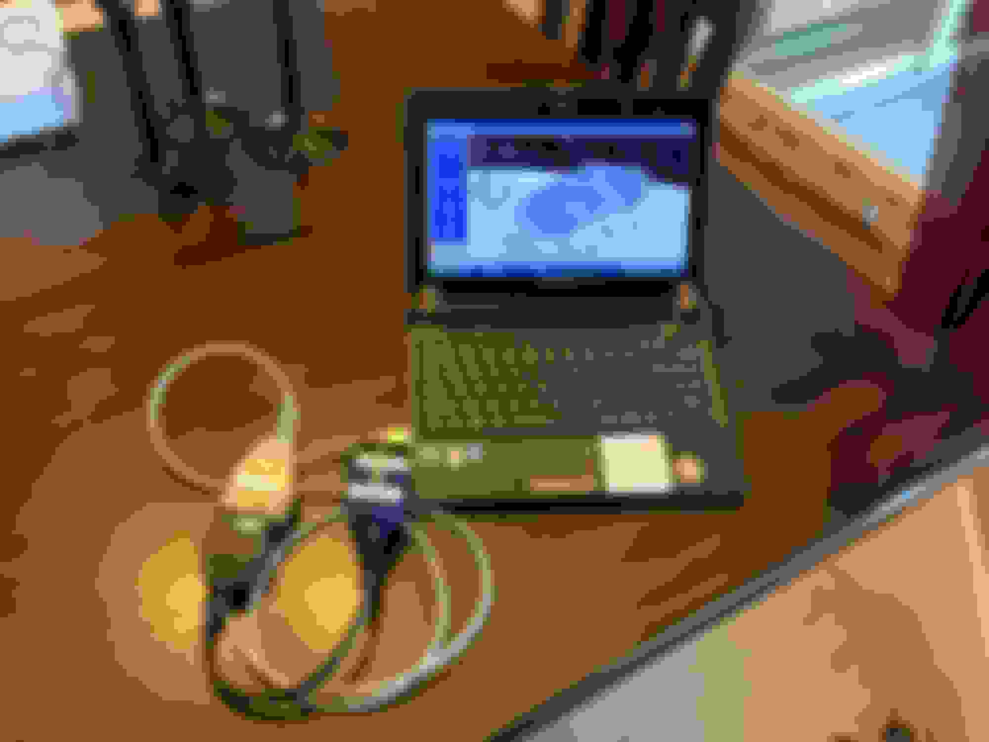
When I finally got around to getting my 4 year old Techstream to work with a laptop (yes, I was not motivated enough until this year to actually use it). I have a 2002 SC430 and when I hooked up the Techstream to diagnose which TPS was bad and which color code to buy, it worked just fine. Afterward, no VSC error light! So the adapter works and no need to go through the reset routine. (Note that this adapter is not needed in the later models that
have the CAN bus in them, I believe that started in 2006?)
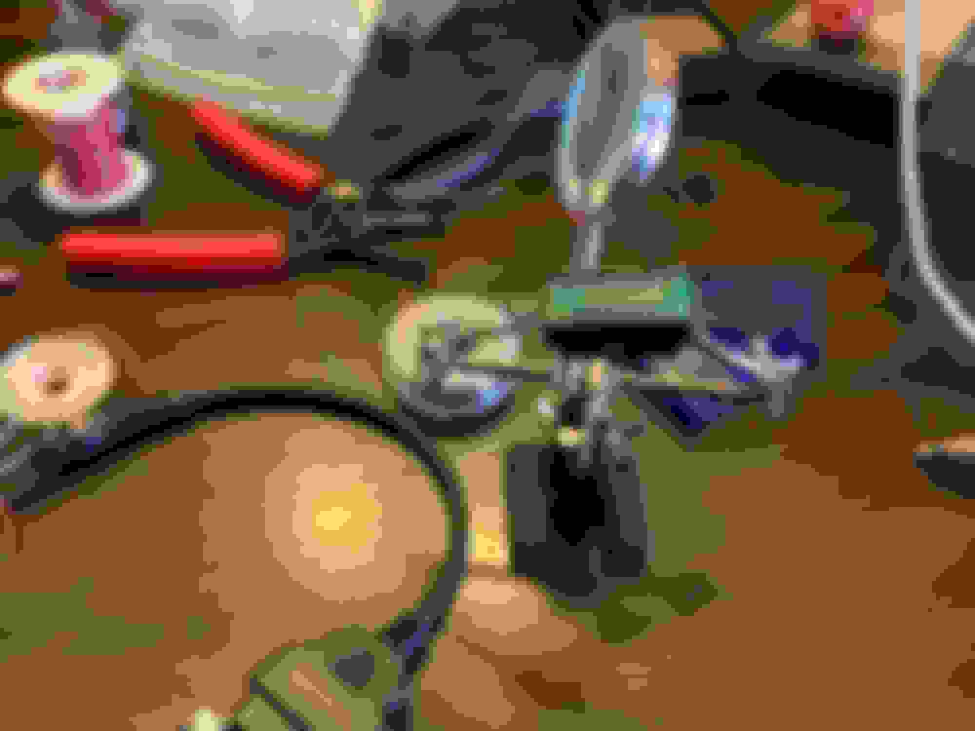
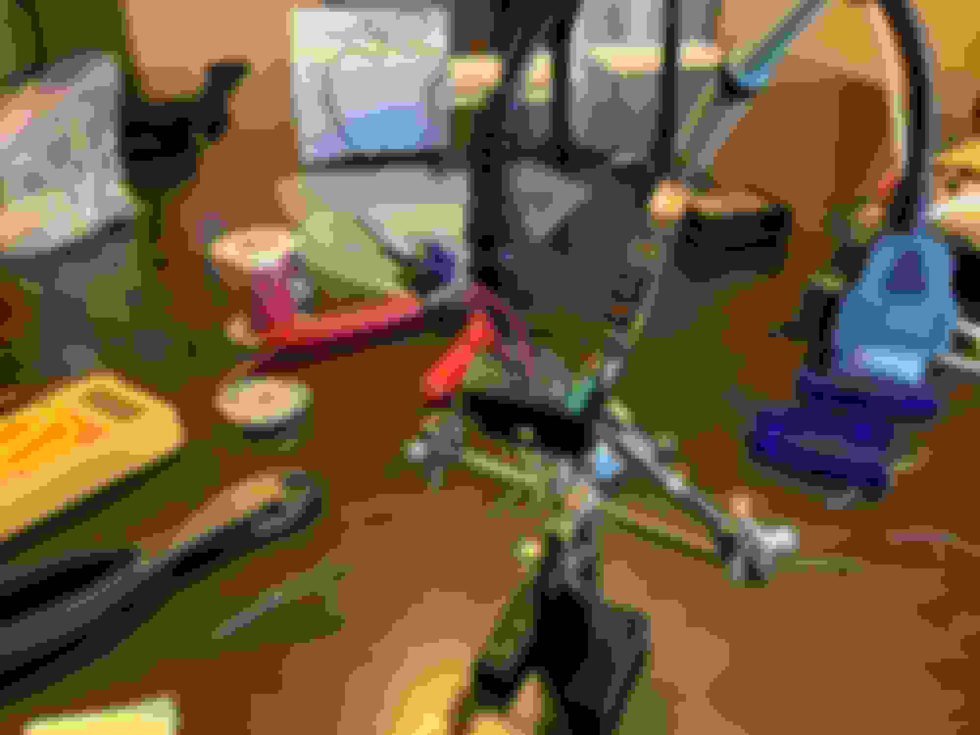
Basically, connect up pins 4, 5, 7, 15 & 16 only. None others. I also made this a multipurpose adapter by adding wires to pins 4 & 14 of the connector that plugs into the car’s OBD II connector. That way, if I ever get a VSC error that needs to be cleared, I can just short out those two wires and that will clear the error. (That's what the X is on the connector, so that I'd know which connector to open up and get to the wires. Had I been further motivated, I'd have brought the wires to the outside and connected a switch to it or something like that, but I didn't have the parts and obviously wasn't sufficiently motivated....)
Here are some pictures:
After you build the adapter as shown above, you just hook the adapter to the end of the Techstream and connect the other end of the adapter to your car's OBD II connector and you're ready to diagnose and make changes to your car without generating VSC errors.
Another advantage to this adapter is that the Techstream is not modified and so it can still be used for CAN applications.
So after reading RetroPlay�s posts # 38, 39 & 54, I decided to make an adapter for when I�d actually get my Techstream up and running, I could run it without generating errors. So earlier this year, I finally got around to making the adapter and it is pretty simple. Buy both the male and female versions of the OBD II connectors, connect up only the pertinent signals and leave off the CAN bus signals that cause the VSC error light to show up.
When I finally got around to getting my 4 year old Techstream to work with a laptop (yes, I was not motivated enough until this year to actually use it). I have a 2002 SC430 and when I hooked up the Techstream to diagnose which TPS was bad and which color code to buy, it worked just fine. Afterward, no VSC error light! So the adapter works and no need to go through the reset routine. (Note that this adapter is not needed in the later models that
have the CAN bus in them, I believe that started in 2006?)
Basically, connect up pins 4, 5, 7, 15 & 16 only. None others. I also made this a multipurpose adapter by adding wires to pins 4 & 14 of the connector that plugs into the car�s OBD II connector. That way, if I ever get a VSC error that needs to be cleared, I can just short out those two wires and that will clear the error. (That's what the X is on the connector, so that I'd know which connector to open up and get to the wires. Had I been further motivated, I'd have brought the wires to the outside and connected a switch to it or something like that, but I didn't have the parts and obviously wasn't sufficiently motivated....)
After you build the adapter as shown above, you just hook the adapter to the end of the Techstream and connect the other end of the adapter to your car's OBD II connector and you're ready to diagnose and make changes to your car without generating VSC errors.
Another advantage to this adapter is that the Techstream is not modified and so it can still be used for CAN applications.
okay Harold, you inspired me...here goes!
gonna add the 4&14 shorting switch, even though I should not need it.
I tested it with the new adapter and without...all tests 100% as expected
without adapter, VSC lights, as expected
used builtin 4&14 short switch, result, performed zero point calibration and reset light.
with adapter, no lights generated and full control of all TechStream software.
Hey BGW, did you ever consider just cutting the wires on the techstream cable instead of making the adapter? Is there a downside of cutting the unused wires?
Would it be possible just to cut the can bus wire? Any idea which wire that is?
Hey BGW, did you ever consider just cutting the wires on the techstream cable instead of making the adapter? Is there a downside of cutting the unused wires?
Would it be possible just to cut the can bus wire? Any idea which wire that is?
sure and great idea but it was more fun to make the adapter...plus my 2007 Can bus will work with the same cable...with out the adapter.
DshngDaryl, yes, as I mentioned in one of my posts, you can remove the resistors (IIRC) that RetroPlay suggested but then, as BGW alludes, you lose the capability to interface with some other vehicles that utilize the CAN bus.
DshngDaryl, yes, as I mentioned in one of my posts, you can remove the resistors (IIRC) that RetroPlay suggested but then, as BGW alludes, you lose the capability to interface with some other vehicles that utilize the CAN bus.
Ahhhh! Good point. I didn't consider multi car use.
Actually, you could. Just open up the cable in the middle with an Xacto knife. (Be very careful cutting through the jacket to not cut any of the wires.) Then once you get to the wires, poke a pin through the insulation jackets one by one and Ohm it out to the connector pins until you find the two you need to cut & terminate or short together (depending on which issue you are trying to solve). Then just tape it back together and you've got an adapter cable. That's a lot easier than the way BGW and I did it.
Actually, you could. Just open up the cable in the middle with an Xacto knife. (Be very careful cutting through the jacket to not cut any of the wires.) Then once you get to the wires, poke a pin through the insulation jackets one by one and Ohm it out to the connector pins until you find the two you need to cut & terminate or short together (depending on which issue you are trying to solve). Then just tape it back together and you've got an adapter cable. That's a lot easier than the way BGW and I did it.
 05-14-17, 07:53 AM