When you click on links to various merchants on this site and make a purchase, this can result in this site earning a commission. Affiliate programs and affiliations include, but are not limited to, the eBay Partner Network.
I just bought a SC430 and joined this forum. I love the car, but the Nav doesn't work. I bought it as-is, so it was no shock to me. I plan to put an Android 10 7" unit in place of the old Nav. I saw where some guys in Russia did it, so I know it can be done. I pulled the Nav out and several of the wires going into the connectors were either pulled from the socket or broken off. I think the door got stuck and somebody put a hook of some kind in there and tried to pull the door closed, ripping the wires. Does anybody have a photo or diagram of where the wires should go?
I could be wrong but replacing the Nav with other unit is not an easy task since it’s tied with the control below. Replacing the ML deck is, on the other hand, very easy.
For your question about the wire diagram, you need to do the forum search on NAV unit. I think this subject was discussed recently.
Thanks GmanSC. Much appreciated. I cannot see trying to revive a Nav that I cannot get updates more recent than 2015, thus my endeavor to put in the 7" Android. I seem to recall someone leaving a circuit board connected and the door would work, but I don't know which circuit board it was. I will have to do some digging. The worst case scenario is that I permanently mount the Android up there and have the door operate manually. The Russian guy that I saw had his Android with the door and tilt fully functional, but not much on how he did it ... not in English anyway. If I can pull it off, I will certainly post here for everyone on Club Lexus!
Thanks GmanSC. Much appreciated. I cannot see trying to revive a Nav that I cannot get updates more recent than 2015, thus my endeavor to put in the 7" Android. I seem to recall someone leaving a circuit board connected and the door would work, but I don't know which circuit board it was. I will have to do some digging. The worst case scenario is that I permanently mount the Android up there and have the door operate manually. The Russian guy that I saw had his Android with the door and tilt fully functional, but not much on how he did it ... not in English anyway. If I can pull it off, I will certainly post here for everyone on Club Lexus!
Hi!
I'm that guy from Russia with Android. If you want to keep your nav door and tilt workable, you have to keep connected this board.
You can put it behind speedometer, there are much space there.
Hi!
I'm that guy from Russia with Android. If you want to keep your nav door and tilt workable, you have to keep connected this board.
You can put it behind speedometer, there are much space there.
Hi Evgeniy! I am so glad that you responded to my post. I don't know how you figured the whole Android setup with the door working thing, but it is awesome. Enough so, that I decided I have to try it. Your guidance on the circuit board made me smile, thinking I might just be able to re-create what you have done. I bought a VAIS auxillary input for my ML system, pulled the NAV out, and I am ready to begin fitting the Android 10 to the NAV chassis. If you happen to have a photo of the white 20-pin connector, please send it my way. Five of the wires are pulled from the connector and I have spent hours on the internet trying to find out which pins they go to. The colors on the wires change from one side of the connector to the other, so the other half of the plug doesn't really help me. I am good with wrenches, but I am lost on the wiring. I have attached a close-up. Great job again on your setup! Definitely better than running around with a tired old NAV screen up there. The white and black wires (left) go to the NAV. The long black, green, and white wires (right) go to the wiring harness. I am as you might say committed at this point.
Hi Evgeniy! I am so glad that you responded to my post. I don't know how you figured the whole Android setup with the door working thing, but it is awesome. Enough so, that I decided I have to try it. Your guidance on the circuit board made me smile, thinking I might just be able to re-create what you have done. I bought a VAIS auxillary input for my ML system, pulled the NAV out, and I am ready to begin fitting the Android 10 to the NAV chassis. If you happen to have a photo of the white 20-pin connector, please send it my way. Five of the wires are pulled from the connector and I have spent hours on the internet trying to find out which pins they go to. The colors on the wires change from one side of the connector to the other, so the other half of the plug doesn't really help me. I am good with wrenches, but I am lost on the wiring. I have attached a close-up. Great job again on your setup! Definitely better than running around with a tired old NAV screen up there. The white and black wires (left) go to the NAV. The long black, green, and white wires (right) go to the wiring harness. I am as you might say committed at this point.
Hi!
I made it another way. Android connected only 4 wires to car electronic ( ACC, +, ground and backup camera) and by RCA cables to aux on factory mark levinson l, backup camera rca cable.
Also ACC, + and ground wires are connected to same wires on factory radio, because if you connect it same wires on nav it won't go sleep mode when you turn off the key.
I think I still need to get the pulled wires put back ...
Originally Posted by evgeniy
Hi!
I made it another way. Android connected only 4 wires to car electronic ( ACC, +, ground and backup camera) and by RCA cables to aux on factory mark levinson l, backup camera rca cable.
Also ACC, + and ground wires are connected to same wires on factory radio, because if you connect it same wires on nav it won't go sleep mode when you turn off the key.
Not familiar with the NAV sleep mode, as mine was dead when I got it ... LOL. Good to know! I will wire the Android (constant 12v+, ACC, and GND) to the radio like you did. My concern is that I don't think the Android door will work or that the unit will tilt if I don't get the pulled wires back where they are supposed to be in the 20-pin white connector, unless they only need the 24-pin black connector to work.
Not familiar with the NAV sleep mode, as mine was dead when I got it ... LOL. Good to know! I will wire the Android (constant 12v+, ACC, and GND) to the radio like you did. My concern is that I don't think the Android door will work or that the unit will tilt if I don't get the pulled wires back where they are supposed to be in the 20-pin white connector, unless they only need the 24-pin black connector to work.
Nav door and tilt will work only if you connect board from my photo with all wires in pins. And important when you connect it nav door must be closed.
Nav door and tilt will work only if you connect board from my photo with all wires in pins. And important when you connect it nav door must be closed.
Also good to know that the NAV door should be closed. You must have gone through a lot of troubleshooting, which is probably why so few have tried it and been successful. The pulled wire situation is on the other end of the 3-plug cable that goes to the board you reference, where there are 2-plugs (one white 20-pin, the other black 24-pin) where the NAV chassis
connects to the dash. I have attached a picture to better show what I am talking about. Without the wires put back in the white 20-pin connector, the NAV chassis is inoperable.
The write-up herein provides exactly the type of info that I need, but unfortunately it is for the adjacent plug which on my SC 430 is black (left). My wires were pulled from the white plug (right). So very close. I sincerely appreciate your effort to help though!
I have found out that the connector on the NAV assembly is referenced by Lexus as:
Name: Multi-display
Code: M5
Part Number: 90980-11971
Color: White
Does anyone have a color-coded schematic or picture of the wiring going into this NAV connector? ... specifically pins 9, 10, and 20?
Fabrication is about done, but still don't know what to do with connector M5 pins 9, 10, and 20.
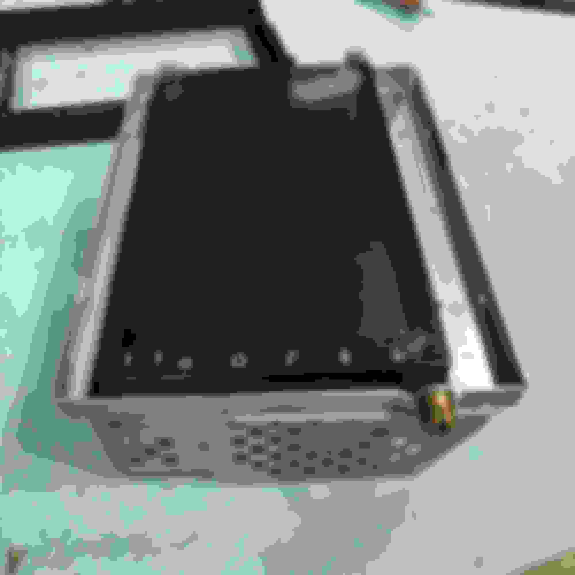
I managed to get the pin assignments for the M5 connector squared away. I bench tested the Android 10 with Bluetooth that is replacing the NAV unit. Here is what it looks like assembled after a lot of cutting, grinding, and fitting.
I don't know if the circuitry will work since it was inoperable when I got it, but I should know this weekend.
Last edited by 2006SC430; 11-03-20 at 01:59 PM.
Reason: Additional info
Fabrication is about done, but still don't know what to do with connector M5 pins 9, 10, and 20.
I managed to get the pin assignments for the M5 connector squared away. I bench tested the Android 10 with Bluetooth that is replacing the NAV unit. Here is what it looks like assembled after a lot of cutting, grinding, and fitting.
I don't know if the circuitry will work since it was inoperable when I got it, but I should know this weekend.
I completely forgot about your thread. I completed 99% of the modifications to the Android and metal frames last night, hoping to finish everything up tonight.
I got stuck on how to affix the Android inside the metal body. Did you have to drill out holes on the side of the metal frame to mount yours? I've drawn arrows below to show which holes seem to line up on mine, but id have to drill those out to use them.
I also noticed in your picture above that it looks like you removed the tabs/screw holes that connect the smaller metal bracket to the main one. How did you go about securing them together?
Yes, I drilled holes on the side of the chassis and used the existing threaded holes in the Android. It took quite a bit of trial and error getting the Android correctly positioned (cutting & grinding) the two chassis pieces such that it aligned with the trim ring. I fastened the smaller metal chassis piece to the larger chassis by making two sets of parallel cuts near the top corners and bending the metal back to form tabs. I drilled through them and into the larger chassis piece, using short sheet metal screws to bind them. With the plastic trim ring, I cannot recall exactly how the top of it fastened (may have used the same holes/screws as the aforementioned) but I do recall drilling and putting a screw through the bottom center between the ribs that the pivot glides upon. I tried so many variations and refitting because of my Android width issues, that it became a bit of a blur. You might be 99% of the way with the chassis modifications, but I was only about 70% done with mine at your stage.

 07-26-20 | 04:13 PM