When you click on links to various merchants on this site and make a purchase, this can result in this site earning a commission. Affiliate programs and affiliations include, but are not limited to, the eBay Partner Network.
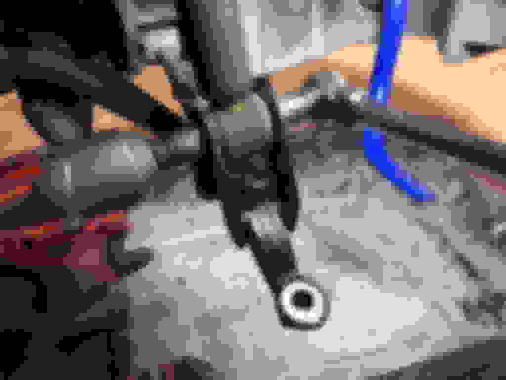
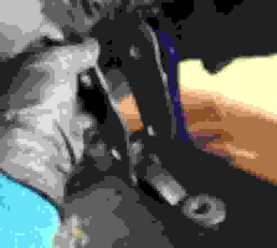
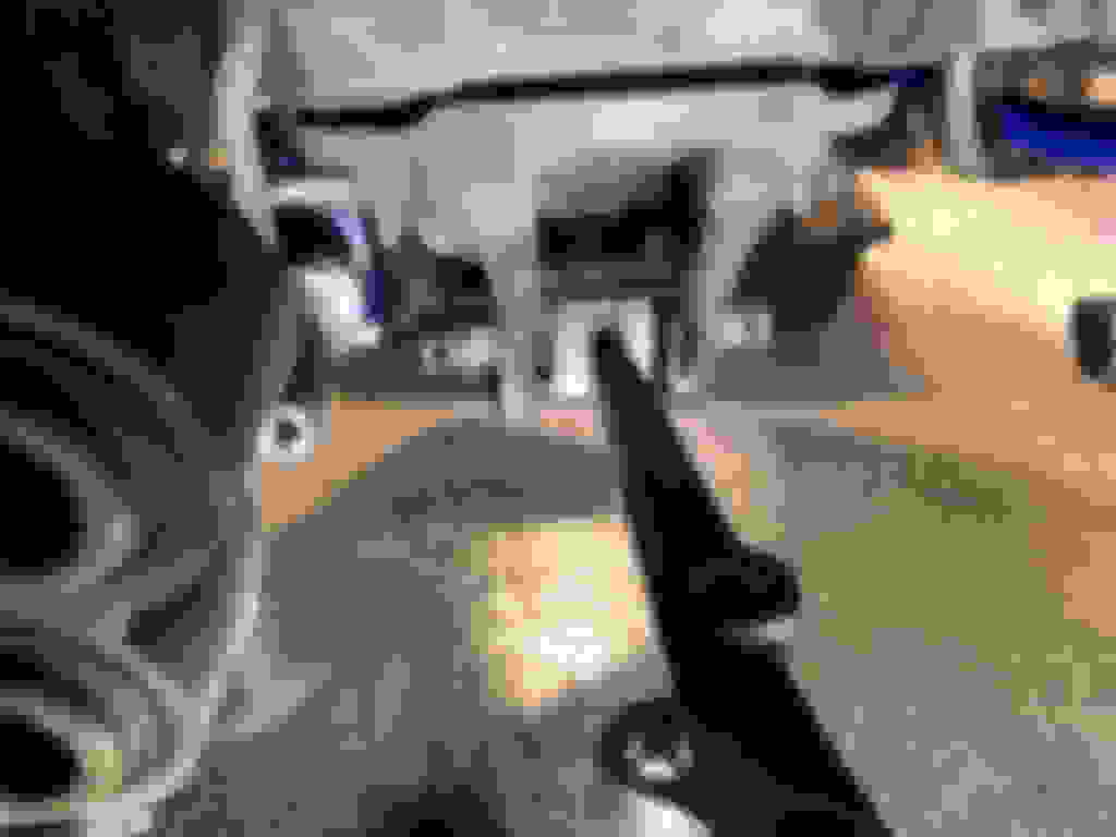
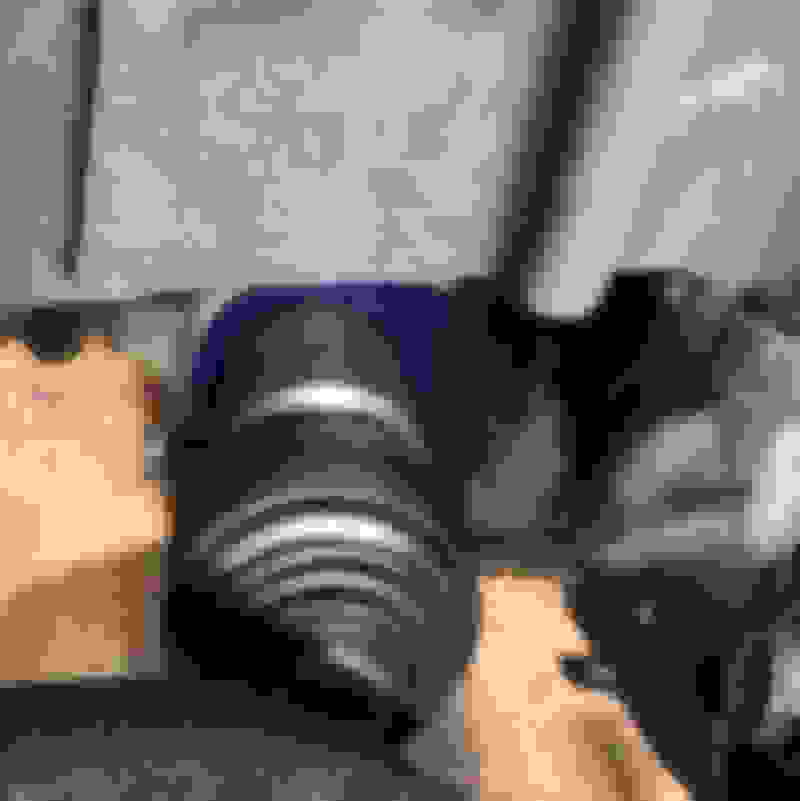
Lower end of strut is secured to shock absorber bracket with 19 mm (116 ft lbs) nut on 17 mm bolt . It is a high torque nut that we have not previously loosened.
Impact driver would not budge it.
Breaker bar to the rescue. After working on the suspension, 75 ft lb lug nuts feel like nothing.
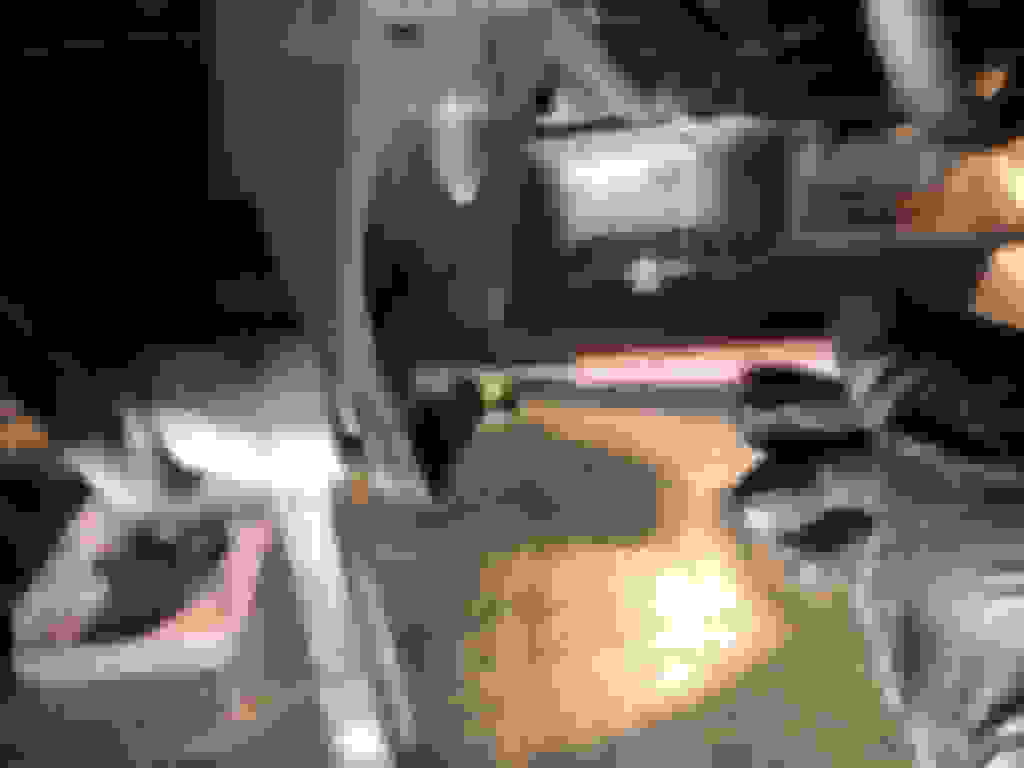
Drift bolt out with punch. Manipulating lower suspension arm may also help ease bolt out.
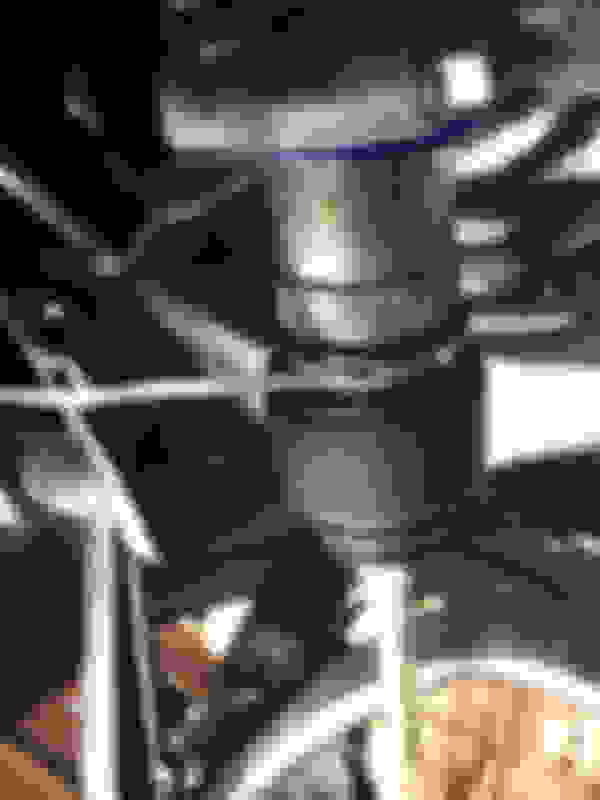
Lower end of strut is still mechanically engaged with shock mounting bracket albeit without a bolt. Only tension and friction are hold lower end. Be cautious when removing last top nut and support the strut in case it suddenly falls.
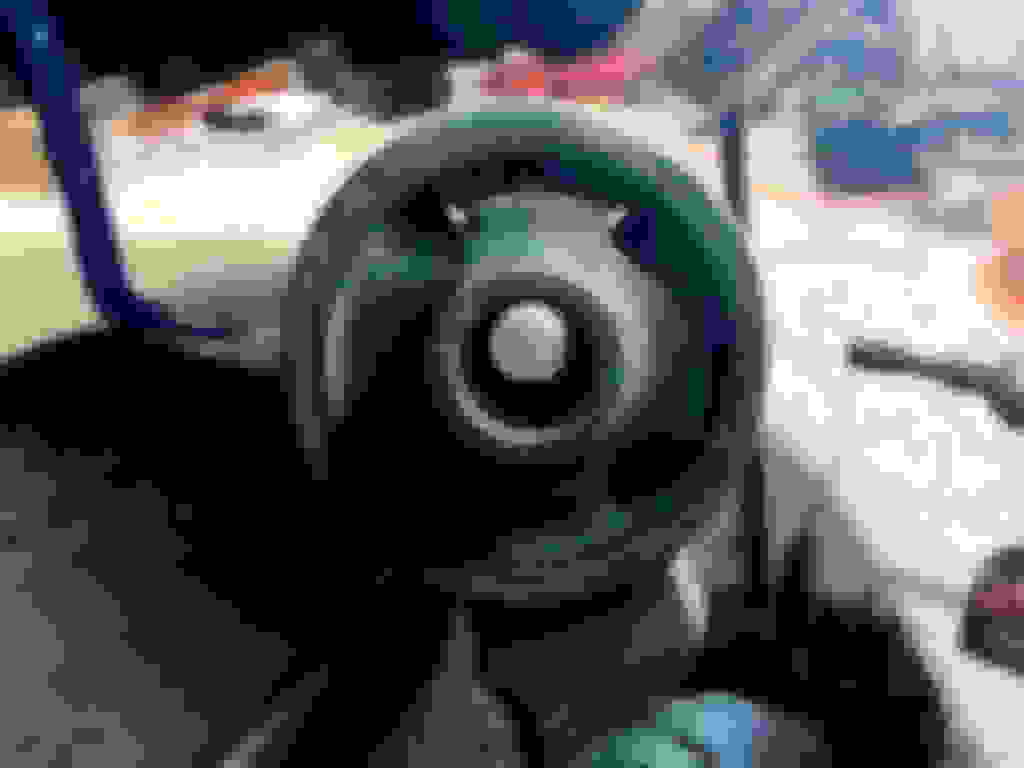
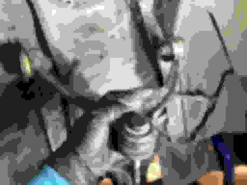
The top shock nuts are 14 mm (41 ft lbs) and easily come off. ABSOLUTELY DO NOT TOUCH THE CENTER NUT OF THE STRUT!!!!!
Once all three top nuts are removed, pull lower end of strut free from lower shock support bracket. The entire strut should come out. Be mindful of the brake line and ABS sensor cable.
Scrape away any remnant gasket from ceiling of strut tower.
Remove suspension support ring for cleaning. Also clean top of strut tower. When reinstalling support ring, its embossed arrow goes towards front of car.
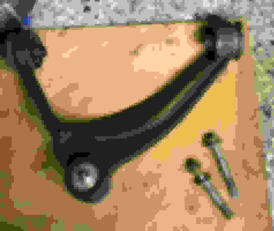
We previously loosen the one nut and two bolts securing the LCA. Loosen the nut until it is finger loose. We take advantage of it to support the LCA while removing the two bolts from below the lower suspension arm.
As a reminder, the LCA nuts and bolts were....
LCA 19 mm nut to stud on bottom of chassis (112 fl lb)
LCA 17 mm bolts to lower suspension arm x 2 (122 ft lb)
Support the LCA while undoing nut completely. Be care of hoses and wires as you remove the LCA.
Most of its is in reverse order, but without torquing up any of the rotational bushings until suspension is loaded.
I'll post reassembly tips later and I still have to cover rear coil over installation.
Last edited by Seattle SCone; 11-19-20 at 07:41 AM.
Front Suspension Reassembly Tips - Upper Control Arm Bolts
Upper Control Arm bolts 14mm (39 ft lbs) were difficult to feed back through UCA bushings and accurately back through holes in chassis. You can't see the holes and the UCA further worsens the situation because the bushings tightly fit into the chassis. So, you can't actually wiggle the UCA around to find the holes. I had to move the UCA with light blows of a rubber mallet or prying with a bar inside the bushings. That took me over and hour on the first side to get both bolts to finally fall through. It was extra messy putting the bolt in and out because I wanted the tip of the bolt to be blue gel loctited and the portion within the bushings to be anti-seized.
The Mevotech UCA's have grease zerks. I loaded them with grease prior to mounting the UCA.
All bolts were wire brushed, washed and alcohol dried before reuse.
TIP: Use a drill extension rod as an alignment tool. The thin end is small enough to pass through the non-visible hole even with slight misalignment. It is also thin enough to pass through the captive nut once you use the extension rod as a lever to get alignment exact. Diameter of my extension was close match to the bolts and the conical taper helps get things aligned as you push the rod in. Then hold the UCA still as you withdraw the rod. Feed bolt into now aligned bushing, far side hole and thread onto captive nut. If bolt does not simply through the near side hole, do not wiggle the bolt. That will push bushing back out of alignment. Instead, lightly thread it into the near end of the bushing.
Using this trick, it took just a few minutes to get both UCA bolts to feed through.
Only hand tighten these rotational bushings. Then will need final torque to 39 ft lbs with suspension under load. If you must tighten more before loading suspension because your loctite working time will be too short, do so with UCA in near horizontal position. That will lock the bushings close to loaded position.
Last edited by Seattle SCone; 11-19-20 at 03:00 PM.
Ball Joint castle nuts can be torqued to full spec without loading suspension. Those would be the ones connecting knuckle to UCA, lower ball joint to lower suspension arm, and lower ball joint to outer tie rod.
Don't forget to put in the cotter pins after each ball joint is torqued up. You can torque up slightly more to align stud hole with castle slots.
One of my ball joints would not allow passage of cotter pin despite perfect exposure of hole through castle nut. Turned out to be a shard of metal inside the stud's cotter pin hole. Cleaned out with a small drill and cotter pin passed through. Probably would be good idea to inspect the cotter pin holes before installing each piece.
Eccentric bolt of lower suspension arm should be positioned to align your previously made marks. That bolt I did antiseize the shaft, but did not loctite.
The eccentric bolt should be snugged with lower suspension arm extending horizontal or slightly up, but not fully torqued until under load. Absolutely, do not lock its bushing with lower suspension arm pointing downward. That would put the bushing extra stress in operating position.
Attach lower castor arm BEFORE adding coilover. If you add the coilover's downward push, it will be harder to avoid cross threading the LCA's two 17 mm (122 ft lb) bolts to lower suspension arm. Those bolts are super prone to cross threading if LCA is not exactly aligned.
LOOSELY attach bushing end of LCA with suspension bracket and 19 mm nut to stud on bottom of chassis (112 fl lb). That will partially support LCA but give enough motion freedom to align LCA flat against lower suspension arm. Both 17 mm bolts should be immediately torqued to spec. I did use blue loctite gel on those bolts. Also put some silicone grease atop the open bolt ends to slow down water ingress from above.
The LCA stud nut must be be torqued up with suspension under load. Before that, simply
Don't forget to add claw washer before threading inner tie rod onto steering rack and torquing inner tie rod to 45 ft lbs. Once, inner tie rod is torqued to spec, peen claw washer over to lock inner tie rod against rotation. I used a combination of direct hammer blows vs drift punch depending on which inner tie rod flat and available approach angle.
Some silicone grease on inside of steering boot's large end helps with re-assembly. However, don't get that on the inner tie rod threads. For the smaller end of the boot you can silicone grease after the boot is in position, by pushing the boot inward and placing silicone grease on shaft.
Secure clamp on small end of boot before working on large end.
Popping the large end of the boot onto steering rack is easier if you let the steering rack compress the boot.
Despite having new large Lexus clamps for the boot, I could never figure out how to use the clamps. Instead, I ended up using some of my stainless steel zip ties. If you have never used SS zip ties, look up the technique for tigthening and locking them in place, It's not intuitive like a plastic zip tie. You have to pull tight, cut off excess, and do a double fold of the cut end while tightening with needle nose.
ABS sensor bracket needs to attach to coilover. Dependiing on the coilover the bracket holder may be fixed in position or rotatable. If it is fixed position, be sure it is facing correct direction when inserting coilover.
I used some silicone grease around ABS sensor o-ring to help seal. On the broken o-ring side, I cleaned up the rust from the sensor and mounting hole. Added a new o-ring of course.
Since I mentioned inserting the coilover, double check that your brake caliper is on correct side of coilover before pushing lower end of coilover onto shock absorber bracket.


 11-19-20, 06:43 AM