When you click on links to various merchants on this site and make a purchase, this can result in this site earning a commission. Affiliate programs and affiliations include, but are not limited to, the eBay Partner Network.
Torque bushing related bolts and nuts with suspension under full load so the bushings will lock into place near their operating position. Otherwise you will lock their inner metal sleeves with the rubber bushing in wrong rotational position. That would keep the rubber under excess stress during normal usage and lead to premature wear.
If you have hub stands, it's really easy to load the suspension and torque. Simply put all four hub stands on and lower the vehicle.
Lacking hub stands, some raise one corner of suspension with a jack to put under load. That was too scary a maneuver for me and is the main reason I got a set of hub stands.
Double check that you got all the bushing related bolts and nuts torqued.
Also, is a good time to double check that all three cotter pins are inserted.
Next would be height adjustment and alignment, but I have to install the rear coilovers first.
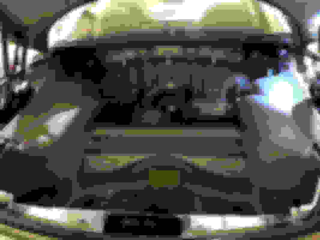
The absolute worst part of the rear coilover install is the infuriating trunk liner removal process. Definitely, not going to do that again if I ever change coilover hardware. My trunk liner now allows full access to the rear strut nuts as well as the adjuster.
I won't cover trunk liner removal in detail, but is is a PITB just to get at the strut towers. Not much special to show except some little extras I've added through the years.
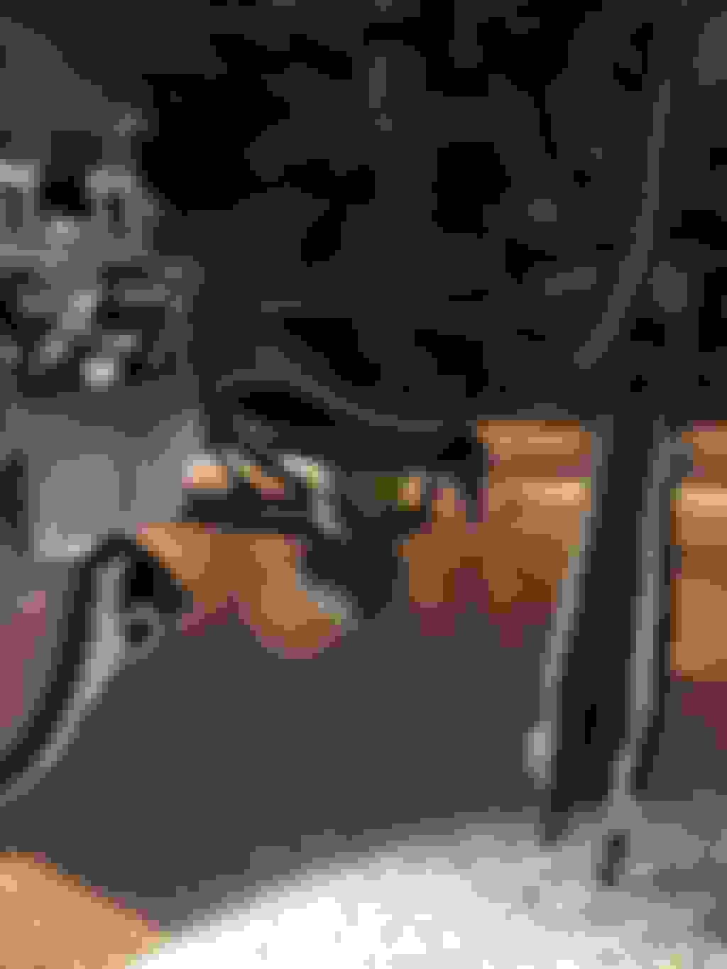
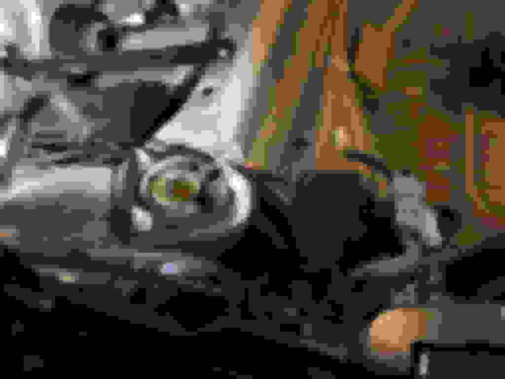
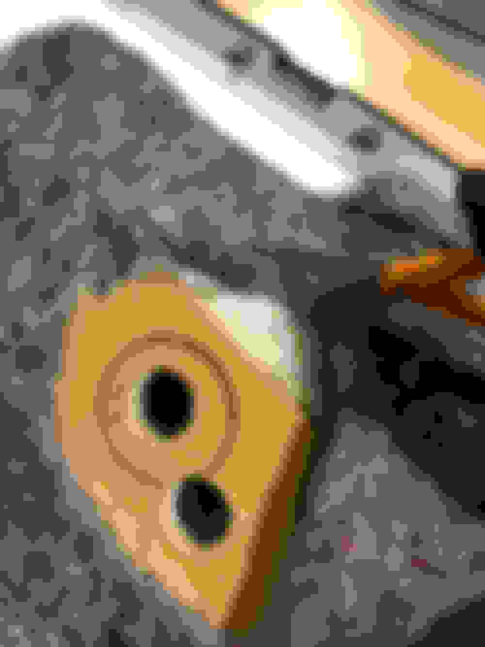
Replaced the puny original subwoofer long ago with a beefier Polk audio sub. Notice how its magnet barely clears the metal work. The original's magnet was SO tiny.
This
Some extra wires on the left side are for my rear camera that goes to my AutoVox mirror dashcam. That rearview camera is my full time rear view and got rid of our SC430's huge B pillar blind spot. Lane merges are so much easier and safer without that blind spot. Took some getting used to things in rear view being smaller and I have to wipe down the rear camera after any wet drive, but that's another story.
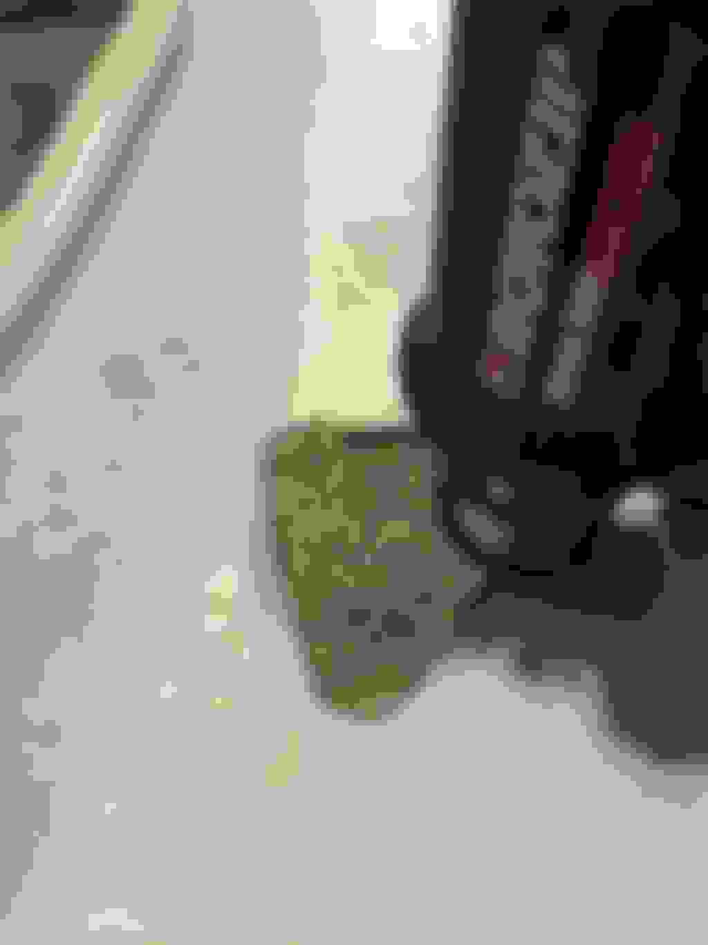
As for front suspension, the first step is to detach sway bar from its links. I have an ISF sway bar and my links have 13 to 10 mm reduction spaces to fit the SC430 links.
Use an allen key to counter torque during removal of 14 mm nut from link stud.
Here is one of my links with reduction bushing on its stud.
On the left hand side only, there is a headlight height sensor arm that. Be mindful of its position when you detach it. You will later need to reattach in same position. Notice its little alignment hook.
Detach three bolts, but just loosen innermost one.
I typically try to remove by torquing nut, but on some of these clearance wasn't enough on nut side, so I torqued from bolt head.
Lower suspension arm bushing nut is 81 ft lb. Sorry, can't remember its size.
Sway link nut is 12 mm (22 ft lb)
Camber nut is 17 mm (81 ft lb)
Once nuts are removed, tap out bolts with drift punch.
Camber bolt is much easier remove if you relieve strut tension by raising lower suspension arm with a jack.
After camber bolt is out, lower jack to release strut pressure. Strut bolt then readily drifts out.
Once all hardware is out, the lower suspension arm swings freely downward.
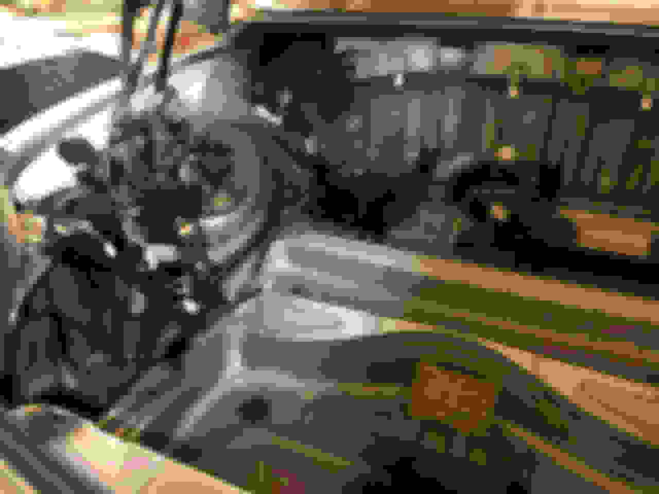
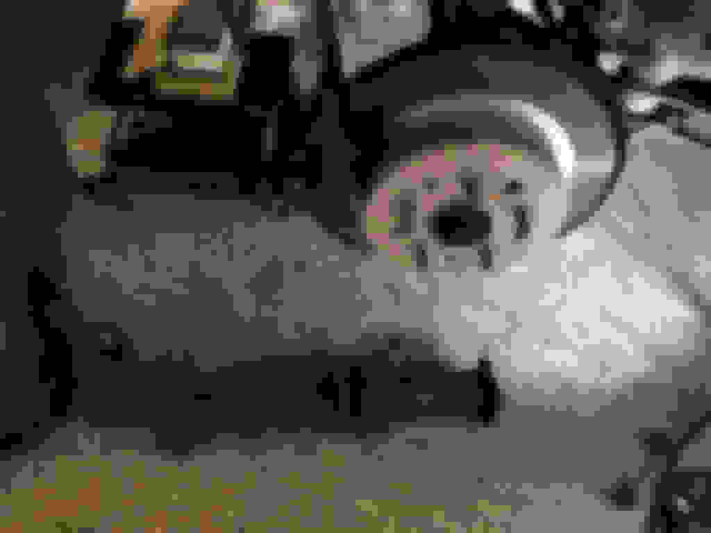
Notice that the brake caliper has NOT been removed. There is enough space to get coilover out without removing brake, but be very cognizant of the brake line, lest a loose strut fall and damage the line.
Last edited by Seattle SCone; 11-19-20 at 03:27 PM.
Remove three 14 mm (47 ft lb) strut nuts. Hold strut firmly during removal of last nut or strut will fall. Do not touch the center nut.
Strut is out
Temporarily move the strut support rings out of way and reposition trunk liner side pieces. Do NOT forget to put strut support rings back into place later.
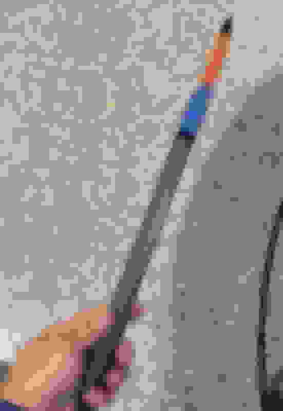
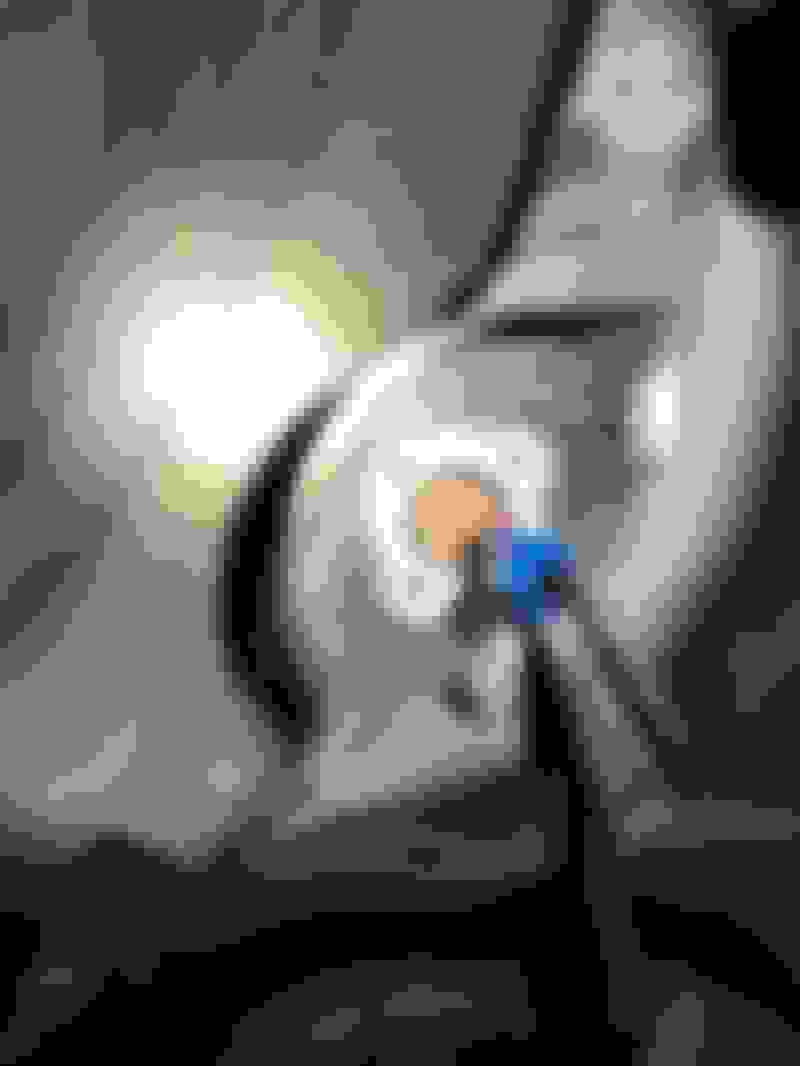
Using a pen on a stick mark position of center and bolt holes.
I needed help to install the rear coilovers. While I raised the coilover blindly from below, my wife called out directions while peering from above. Then she put on the ring supports and spun on the 14 mm nuts. Those got torqued to 47 ft lbs and with blue loctite.
Originally planned to make four small holes or one large hole, but changed plans to a triangular hatch. For that to work, the fitment needed to be exact. This required an extra removal and installation of the trunk side liners.
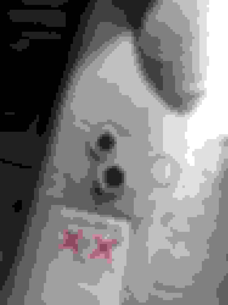
Using the previously make ink marks as rough location, I cut two holes into the liner that were inside the expected final hatch area. Also removed insulation from area.
Wear gloves while manipulating the insulation. It looks innocent, but it is definitely not.
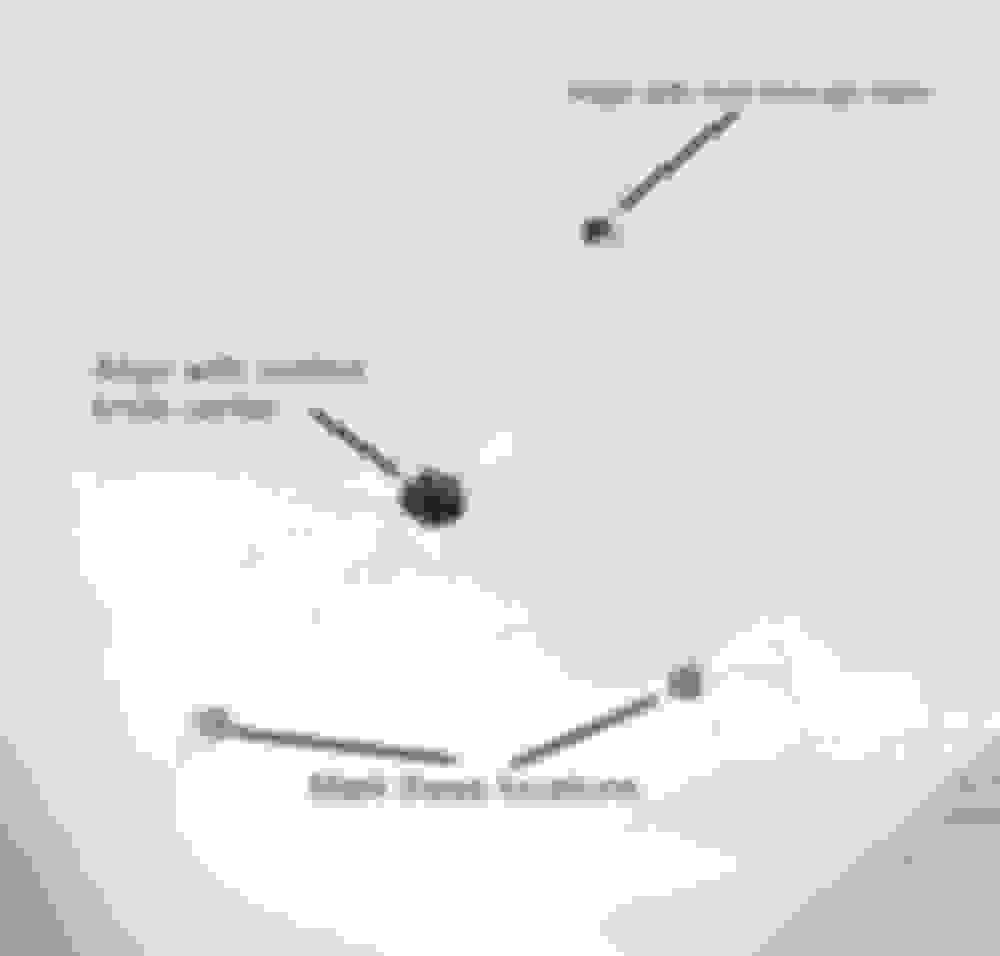
Created an exact bolt hole location template by pressing a piece of paper against original strut's studs. The impressions were then cut out with a hobby knife.
With liner reinstalled and carefully positioned, I could site through my template and center the holes against the actual center **** and one of the studs.
With all locations accurately located, the template was removed and I drew 30 mm diameter circles centered on each bolt location.
Connected the tangents and my opening was laid out.
Removed liner and used Rotozip to cut out final opening.
Clean up edges with knife
Reinstalled liner
Triangular openings allow adjustment and gives access to strut nuts, but is smaller than a large diameter hole.
I will 3D print custom shaped covers for the hatches later. Here is a preview of a preliminary 3D model for the covers.
Last edited by Seattle SCone; 11-19-20 at 10:15 PM.
Rear suspension reassembly was fairly simple. I used antisizes for inside the bushings and locktite for the nuts (except the camber nut).
The tips I would offer are...
1. Use jack to raise lower suspension arm when installing the camber bolt. Otherwise coilover will tend to push lower suspension arm too far down to allow camber bolt passage. I guess you could strong arm it, but a jack was super easy.
2. Look out for the height sensor's position and that its little tab goes into its hole as you tighten the sway link bolt.
3. Don't forget to pull the gas cap emergency release back in through the left side liner.
Last edited by Seattle SCone; 11-19-20 at 04:18 PM.
As for front suspension, the first step is to detach sway bar from its links. I have an ISF sway bar and my links have 13 to 10 mm reduction spaces to fit the SC430 links.
Use an allen key to counter torque during removal of 14 mm nut from link stud.
Here is one of my links with reduction bushing on its stud.
It's only been in there for a little over a month, but I don't see any wear and the fitment still feels like when I first made them.
Given that some are using plastic in that same role, I'm not terribly worried about the aluminum, but I can check them again in a few months.
I've done a preliminary alignment with most of the emphasis on getting the previously severe cambers corrected and toes set to be about 1/16 total inward front and 1/8 total inward in rear.
Took her it out on the road. No pulling. Turns in nicely and stays pointed where I leave it. Even better -- No more steering wheel vibration at 65 MPH.
Completely different feeling care post the work and I am pretty happy.
Course, the steering wheel is off center, but I'll get that adjusted out by the time I'm done. I expect the alignment will take me a whole day with the rears being the most troublesome.
Those are still on the OEM eccentrics with their not so fine adjustability.
Now that an hour of road time on the new suspension allows some settling, I'll work on a more refined alignment.
Thank you so much. Very impressed that you completed all of this work, and did so while documenting in photos and description all of the steps. This is a huge help to so many of us in this community!! Bravo!!
David
p.s. Have my reduction spacers for my ISF 17MM rear sway bar coming from Figs, thanks to your information !!
As for front suspension, the first step is to detach sway bar from its links. I have an ISF sway bar and my links have 13 to 10 mm reduction spaces to fit the SC430 links.
Use an allen key to counter torque during removal of 14 mm nut from link stud.
Here is one of my links with reduction bushing on its stud.
How has that aluminum reduction spacer help up?
Last edited by RC51; 11-19-20 at 11:18 PM.
Reason: duplicate

 11-19-20, 02:16 PM