When you click on links to various merchants on this site and make a purchase, this can result in this site earning a commission. Affiliate programs and affiliations include, but are not limited to, the eBay Partner Network.
Figs Engineering Front Suspension Rebuild and Coilovers Project
The 18 year old suspension parts in my 2002 SC430 were definitely tired at 222K miles. Time for replacement of worn suspension components to keep her fun and safe. There wasn't detectable looseness when manually jostling the wheels, but the lower caster arm bushing was in sad shape.
This thread documents how I did my front suspension refresh for purpose of entertainment, but should not be construed as the best or correct method. Techniques used and torques noted are simply what I followed, and may contain errors. Always double check with other sources. The author is not a professional mechanic and this should not be considered advice.
Figs engineering had both bushing sets and entire new parts kits. I opted to replace entire components with bushings already in place. More cost, but I wanted to minimize down time and struggling with getting bushings replaced wasn't worth it to me.
My other choice was coilovers vs rebuilding the struts. I wanted to keep stock ride height due to snow driving needs, but also wanted a higher spring rate to match another of my vehicles. Also, desired adjustable damping. The car is a daily driver and will never be on a track. Just wanted a more fun ride in and out of work. Based on my desired ride characteristic, Figs suggested 10Kg/mm front and 10 Kg/mm rear spring rates in the BC Racing BR Series. Standard springs, but built with longer shockers to maintain stock ride height.
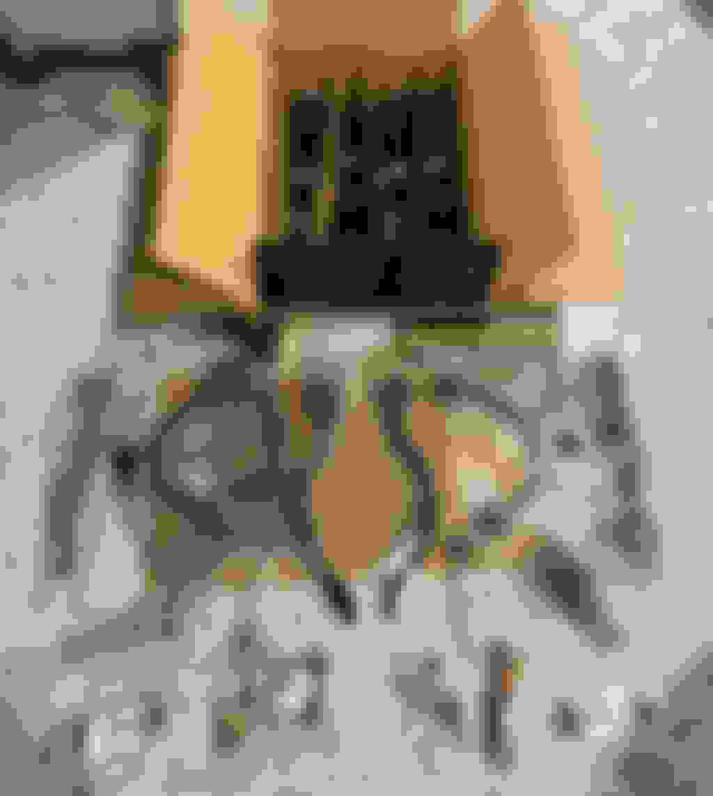
BC Coilovers, upper control arms, lower support arm, lower castor arm, ball joint, inner and outer tie rods from Figs.
Took about seven weeks for the customized coilovers to arrive from Taiwan. They arrive already with perches already set to achieve stock ride height.
The refresh kit arrived much sooner, but it was pointless to install the parts only to repeat a lot of work to install coilovers later. Better to wait and do it all at once.
For good measure, I also obtained front and rear sway links to the set of goodies.
Two minor parts issues in the kit. Figs had received a run of left outer control arms from MevoTech. Externally they looked perfect, but their internal threads were messed up. Could not be threaded onto inner tie rod. Also, my left upper control arm was missing its zerk fitting. Fixed problems with a visit to Oreilly's. Car was already taken apart and I could not wait for a shipped replacement.
Last edited by Seattle SCone; 11-19-20 at 09:29 PM.
Baseline wheel alignment and corner balance data were obtained on the worn stock setup. The old parts were worn, but she still drove straight down the road and wore tires evenly. The main bad symptom was the all too common steering wheel vibration around 60-65 MPH that happens with practically anything awry with the suspension, alignment or wheel balance on the SC430. The majority of 18 years ownership has been accompanied by that "characteristic." Only brief respites from those symptoms have been enjoyed.
As per residential code, my garage floor is definitely sloped towards the door. Over the 105 inch wheel base length, there is about 3/4 inch drop. Due to the way my QuickJack works and pretty severe suspension droop when car is raised, it simply was not practical get the wheels all level. However, my main interest in is cross balance, and I can get that data with the scales leveled left/right and thus in-plane.
Paco Motor Sports steel base plates were leveled left/right using laser level and layers of self stick vinyl tiles attached under the plates. The plates were also individually bubble leveled by pieces of vinyl tile under areas of plates to get each one level. Up to five layers of vinyl were needed to get the plates in-plane. Steel plates leveled left/right and individually to get all in-plane
With a planar base, I could proceed to get cross balance on the OEM setup.
Laser cross lines help getting car in same position
I mentioned Quickjacks. They are fantastic for securely raising car 21 inches for work, but challenging to use if the car needs to land accurately atop a target due to their fore-aft pivoting motion. They don't lift a car straight up, but instead around a pivot points of a parallelogram. That means the car ****s about 4 inches fore/aft between initial touch down and full weight bearing. Also, don't forget that suspension pushes out about an inch as load is borne. Ideally, I would land the car with my PACO hub stands upon my scales, but that is way too dangerous a maneuver in my book. The bearings of the stands are 10 inches apart and the scale is 15 inches square. Add the ****s and you're asking for trouble. So, weights were done with wheels on instead of hub stands.
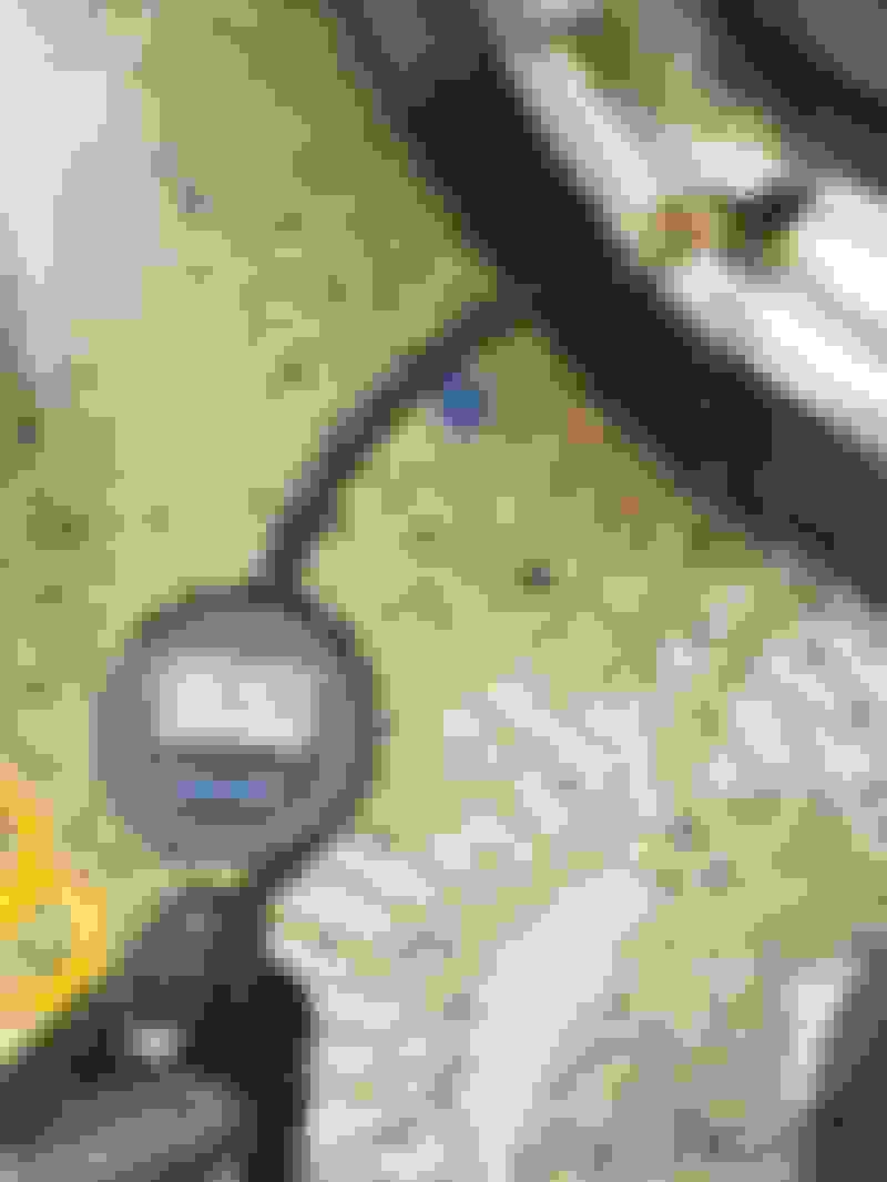
To allow slippage of wheels atop scales, I used large zip-lock bags with a spray of lubricant inside the bags.
Lubricated ziplock as slip "plate"
Tires were freshly filled to my usual pressure 36.0 PSI
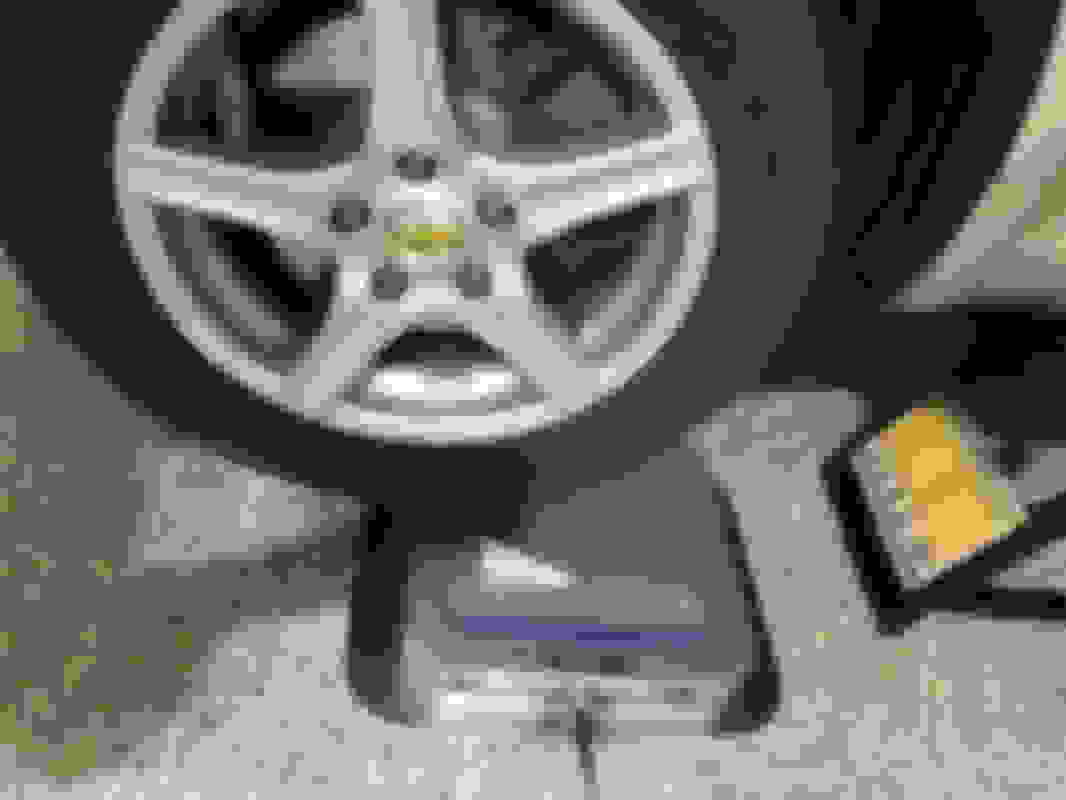
Here you can see how far forward the must be just before touchdown on scale. The Quickjack's fore/aft motion means I must position the scales so final position is centered on scale.
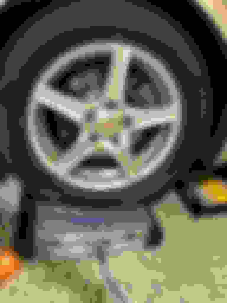
Finally, all four wheels on scales.
My mass in weight plates and kitty litter were placed on passenger sit. Also, car is at 1/2 fuel capacity.
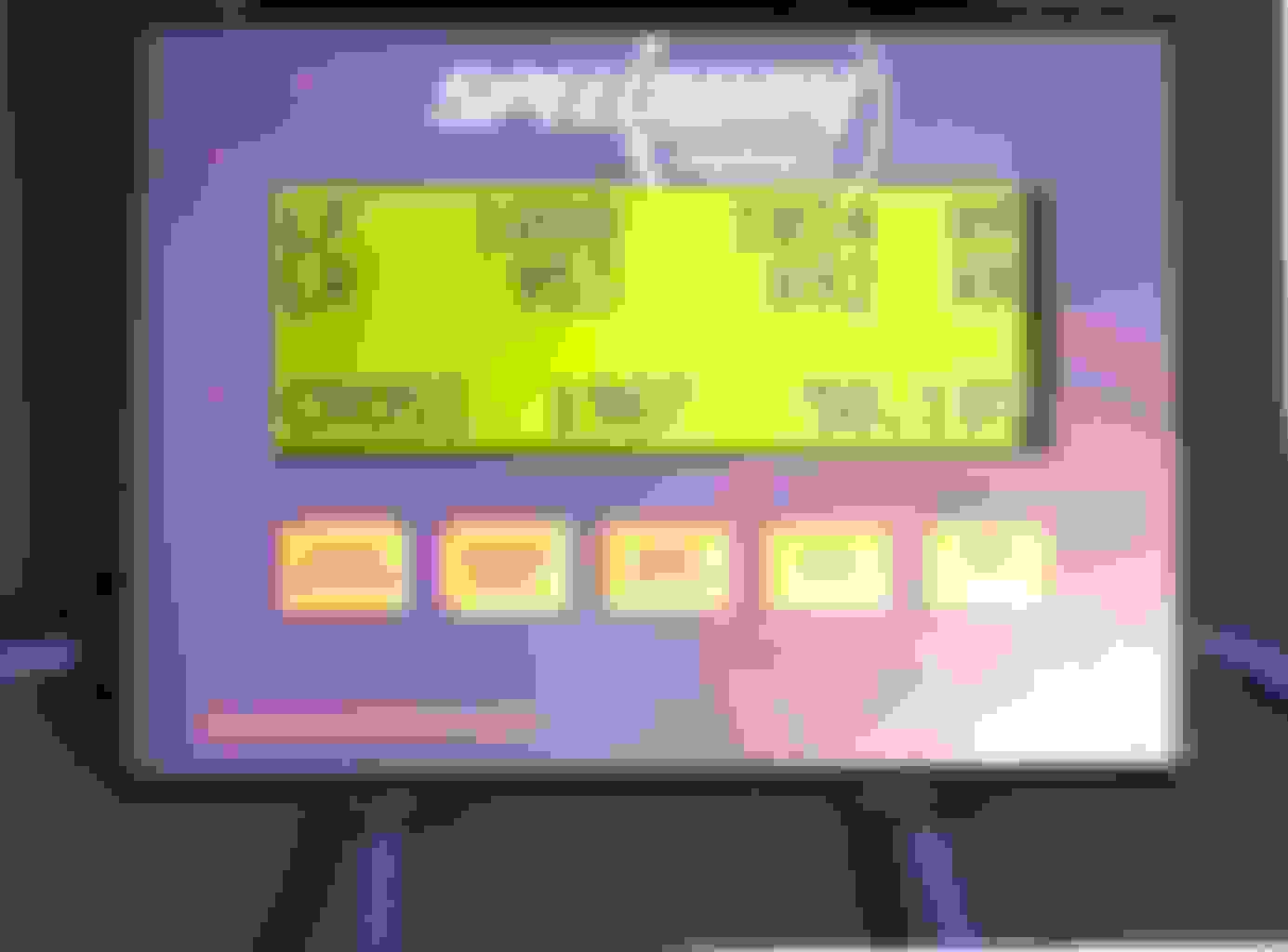
And here is the OEM cross balance....
I was surprised by how well the worn OEM suspension was cross balanced.
Next, scales were removed and wheels replaced by Paco Hubstands and lowered on the steel plates. Steering wheel was verified level.
Goal was to obtain baseline toe, camber, thrust angle with worn, OEM parts.
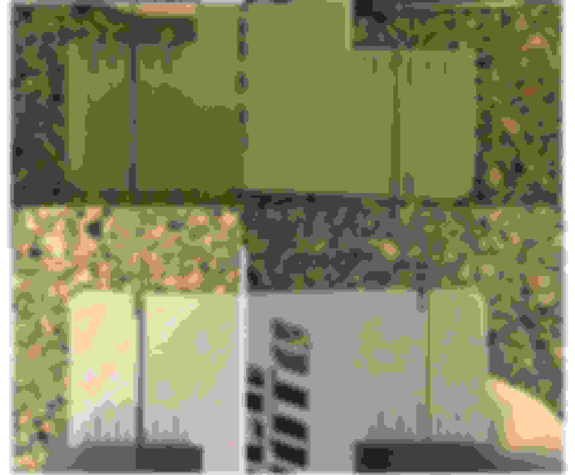
Paco Hubstands have built-in toe plates, but also stretch a steel wire and springs between each front and rear of each toe plate. That wire is NOT for measuring toe, but rather for examining thrust angle. They don't mention it, but I think it also helps with understanding steer ahead angle. You compare the wire position left/right on the scale markings. If thrust is straight ahead, the displacements should be equal in magnitude, but opposite direction.
In this composite pict, the rear stands at bottom and left is left. Original thrust angle is slightly to left. Steer ahead is slightly right.
I didn't measure castor because it isn't adjustable on the SC430. Might have been interesting because my original LCA bushings were pretty shot, albeit not clunking.
front total toe = 0 (yes, zero)
front left camber -1.50 deg / front right camber -1.25 deg
rear total toe = 1.5 sixteenths inch toe in
rear left camber -2.40 deg / rear right camber -1.95 deg
Ride heights were measured from PACO stand toe plate to fender metal.
front left 25 13/16"
front right 26 3/16"
rear left 25 5/16"
rear right 25 11/16
My interpretation was...
The old struts were no longer keeping ride height anywhere even. Yes, those struts are worn. It never did the old Cadi up and down, but wow.
Front camber with slight more positive on right so it will slightly pull to right which is same deviation direction as the apparent steer ahead. Zero toe was not helping with keeping car straight line stable. I always thought it was the road camber that I was often needing slight leftward steering wheel effort.
Rear cambers are really out of balance and thrust angle is wrong.
It is a wonder I'm accustomed to driving the car in this condition. Last alignment was by the Lexus dealership about 2 years ago. Oddly enough, my tires wear evenly despite all these issues.
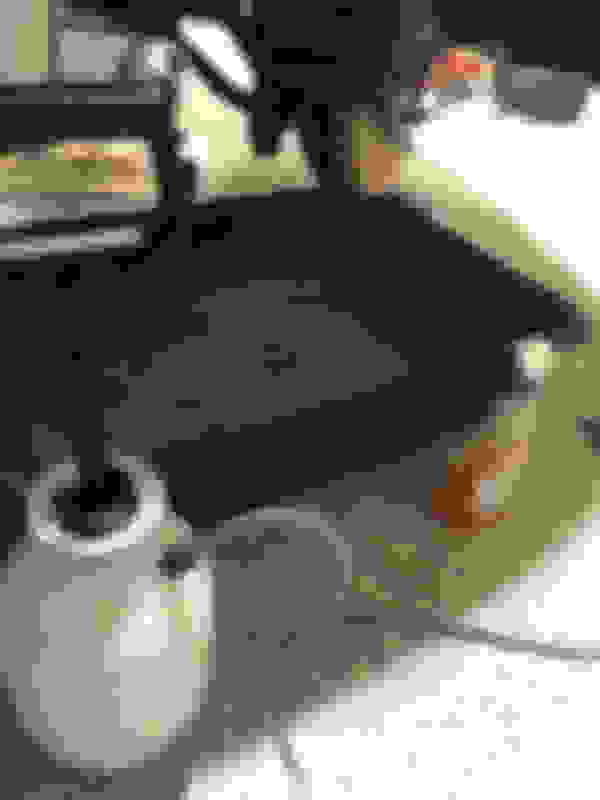
There was huge temptation to just start wrenching, but you'll be glad you pre-cleaned the suspension components. Years of dirt and oily debris are messy, slippery and increase the risk of contaminating internal parts of components being retained. In my case, I was not replacing the brake system, and knuckle.
I used degreaser, a nylon brush and hot water in a sprayer to rinse into a catchment tray. If your garage floor isn't sealed, add layers of cardboard to absorb that which inevitably misses the tub.
Many of the suspension bolts and washers are far over 100 ft/lb torque. Those are extra fun to after 18 years!
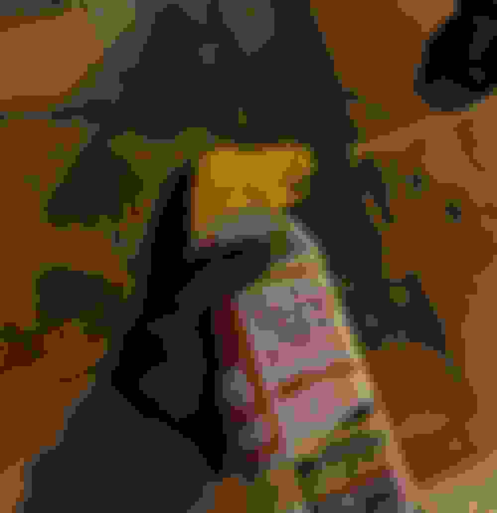
I sprayed all the nuts and bolts with PB Blaster penetrating oil and let everything soak overnight.
That completes the boring part of the project. Tons more picts to post...
It's the next day and time to spray all the nuts again with PB blaster before doing any work. It will soak in while I take care of under covers and braces.
Remove both front and rear engine under covers. Their billions of 10 mm screws have two lengths. Most are longer ones, but keep track of the short ones that go into the limited depth green plastic inserts. Because mine were a bit rusty after 18 years, I replaced most of those 10 mm screws with new ones.
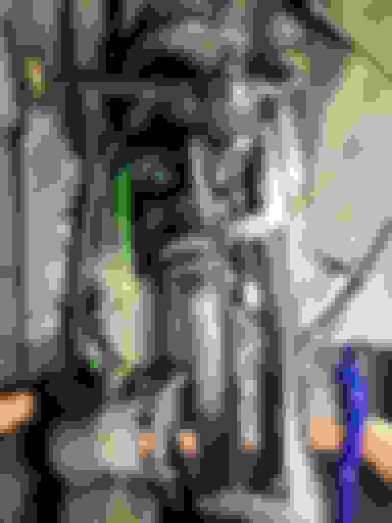
The front suspension brace subassembly and triangular shaped, strut bar bracket at each end of the brace sub-assy must be removed to allow later removal of the lower castor arm.
43 ft/lb nuts and bolts hold the bracket and brace in place. There is also a larger nut for the LCA at the bracket, but leave that alone for the moment.
You don't need to remove the straight brace member. Simply pull it down off the mounting bolt.
Suspension brace subassembly removed
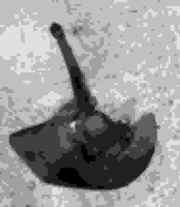
Remove both left and right side plastic covers that surround each end of the sway bar. Those are held by two 10 mm screws.
Side plastic covers as viewed from below. A long socket extension is helpful.
Last edited by Seattle SCone; 11-19-20 at 02:11 AM.
My strong advice is to break the really tough nuts and free before doing any removal of parts. Take advantage of the suspension system's rigid geometry to make breaking things free easier. If you partially take things apart an then tackle a tough bolt, there won't be as effective bracking against which to apply torque. I estimate 1/3 of total project time was spent freeing stuck connectors on my first side. On the second side, I knew better and broke all the tough ones free first.
Milwaukee cordless mid-torque impact driver helps
I like to see my socket sizes at a glance.
BTW, wheels should be off of course.
Some of the bolts like the LCA to lower support arm and ball joint bolts were immovable by the impact wrench even at full 1500 lb impact. Those bolts are vertically mounted upward with exposed top ends.
Fortunately, I could break those free with a 25 inch breaker bar and full muscle power. Never needed to add heat, just the PB blaster pre-soak.
These are the nuts and bolts I would break free first. JUST BREAK FREE. DO NOT REMOVE. Turning wheel left/right can gain better exposure.
I list their original torque spec and how hard they were for me to break free. You can expect to apply more to break them free.
LCA nut to stud on bottom of chassis (112 fl lb) easy
LCA bolts to lower suspension arm x 2 (122 ft lb) difficult
Ball joint bolts to knuckle x 2 (83 ft lb) difficult
Brake bracket bolts x 2 (87 ft lb) moderate
Brake caliper bolts x 2 (25 ft lb) easy
Ball joint castle nut to lower suspension (83 fl flb) moderate (remove cotter pin first)
Break the above free first and things will go much faster later. If you try to break them free later in the process, they will be much harder to remove.
Last edited by Seattle SCone; 11-19-20 at 05:33 AM.
Mark brake disc and one stud so you can put the disc back in same clock position. Hopefully, your brake tech took the time to actually clock them to attain lowest runout. By marking the disc and one stud you can match during reassembly.
Brake caliper is held by 14 mm (25 ft lb) bolts x 2
Brake bracket is held by 17 mm (87 fl lb) bolts x 2
You may need to apply counter torque on the slide pin using a THIN 17 mm wrench. I had to grind one of my 17 mm wrenches down to be thin enough.
BTW, don't be distressed by the apparent rust on my disc. It's actually a very fine amount formed after my pre-wash of components. Wears off immediately with first brake use.
Once caliper is removed, brake pads, springs and shims may fly apart from bracket. Be ready.
Hang caliper safely without overstraining or twisting hose. Your hanging position will move during the rebuild process.
(One tip during reassembly, be sure brake caliper and hose are on correct side of strut before pushing strut into position. Don't ask how I know.)
Put brake bracket, pads, springs, shims, and bolts safely aside.
Detach both ends of sway bar from end links. Gets sway bar out of way and prevents it from tensioning as left and right suspensions have differing heights during disassembly.
Some DIY's show ABS sensor and cable left attached to hub. I am glad I decided to detach ABS sensor from hub.
Detach ABS cable from strut. It is held by a 10 mm bolt and single washer.
Clean the area around the ABS sensor as thoroughly as possible. You don't want debris falling into the reluctor housing.
A 10 mm bolt (69 INCH lb) and two washers hold sensor in place.
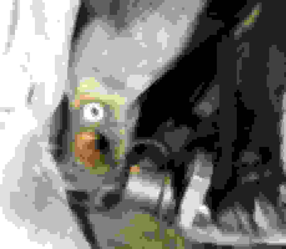
O-ring failure has occurred. You can see the broken, stiff o-ring.
Some rust formation was on sensor and reluctor ring. Must clean this up and replace o-ring and add silicone grease.
Had I followed the usual DIY, I would not have discovered this issue.
This was going to become a problem if I didn't discover!
Plugged ABS sensor mounting hole to prevent debris entry.
Finally, tucked ABS sensor and cable in fender well liner.
Last edited by Seattle SCone; 11-19-20 at 04:10 AM.
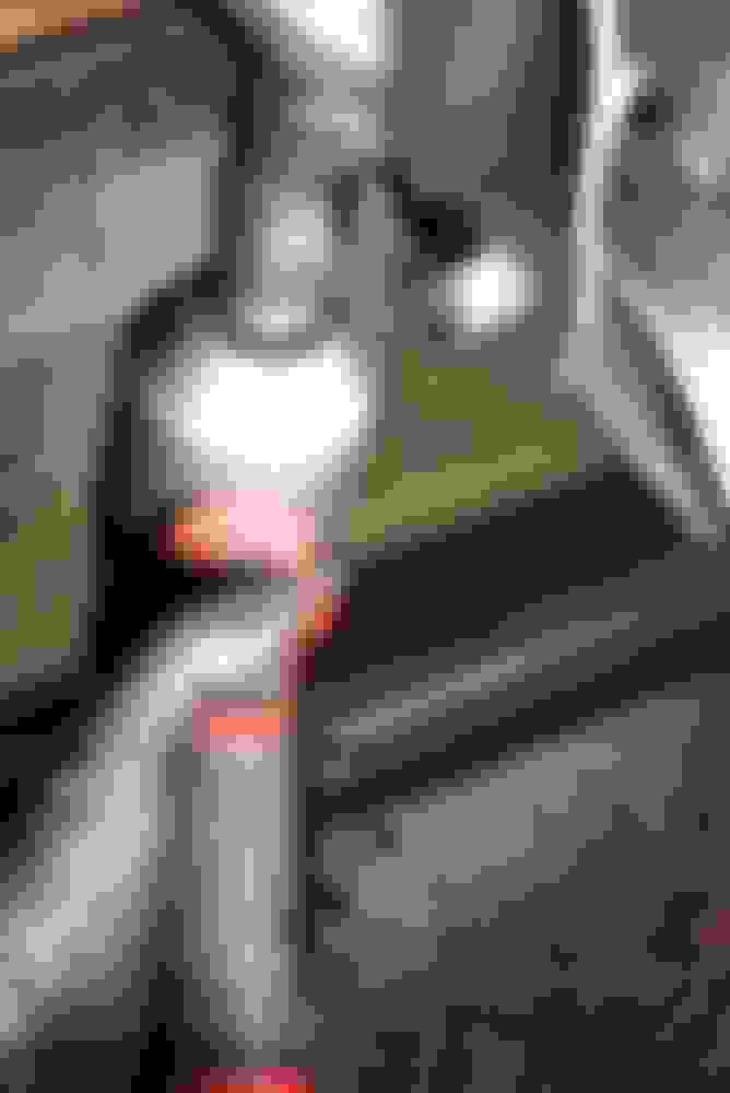
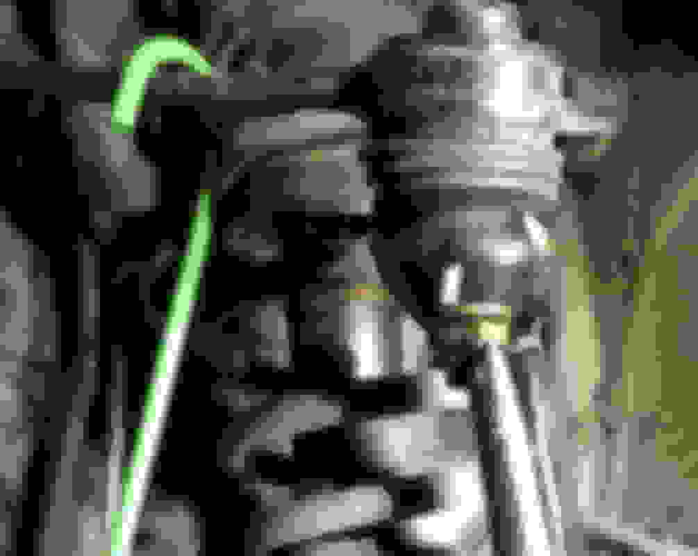
On the driver side only, detach height control sensor from shock absorber bracket.
There are two nuts that appear removable, but the weird, fluted/castle shaped nut is easiest to get counter torque. I have no idea what this kind of nut is called and was expecting to need a special tool.
Fortunately, a normal socket fits the odd shaped nut.
Af this point, the fragile height and ABS sensors are safely detached.
(ABS sensor is attached to bracket because I took this pict after reassembly)
Because we've already broken free the tough bolts and nuts that easier to address while knuckle is unable to rotate. If those tough bolts and nuts have not already been broken free, go back and get those loose.
Remove cotter pin from outer tie rod ball joint stud. The OEM cotter pin is a harp shaped unit, but this one had been replaced with a regular straight cotter pin.
Remove tie end 17 mm castle nut (64 ft lbs) from tie end stud.
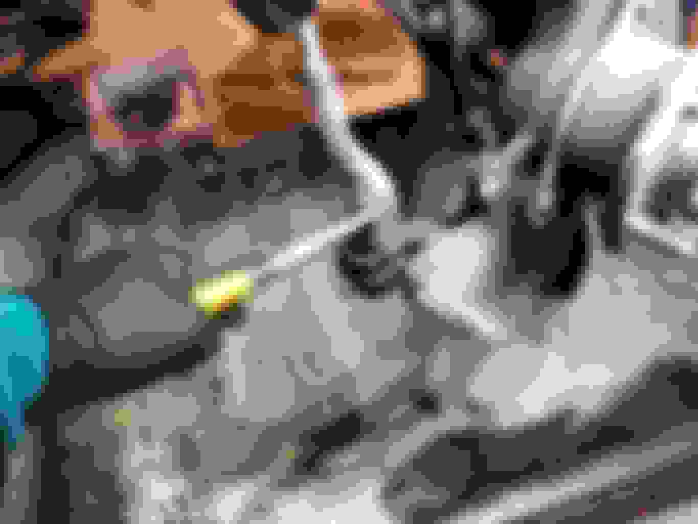
Pop tie end out of Lower Ball Joint using ball joint remover. I really like the Pitman style of ball puller because it preserves the rubber boot. Pickle forks tend to destroy rubber boots.
Simply position on ball joint and turn in tool with ratchet. Ball joint elegantly pops out undamaged.
Mark tie rod jam nut position. Doing so lets you thread the old parts back together so you can match lengths on new tie rods pieces. That should get you close enough to limp to an alignment shop.
Old tie rod ends are often seized together with rust. Despite my best efforts with normal wrenches and PB blaster, I simply could not get jam nut nor out tie rod to spin. Longer wrenches would help, but there wasn't space below car.
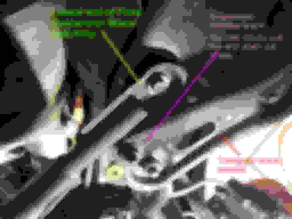
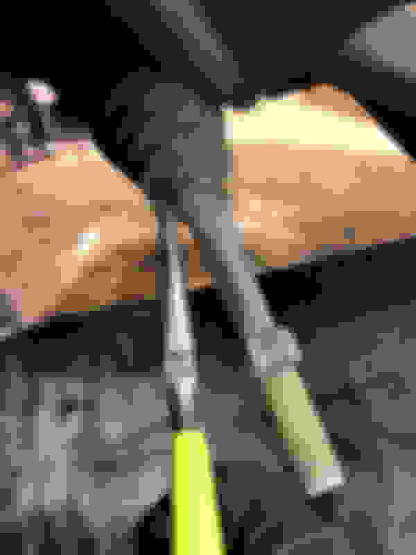
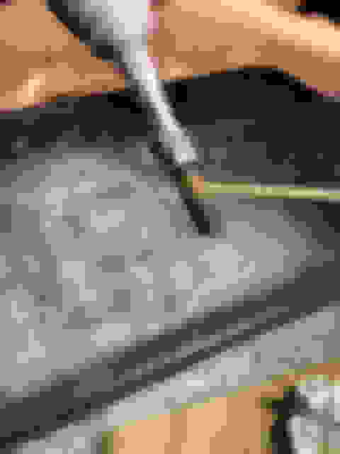
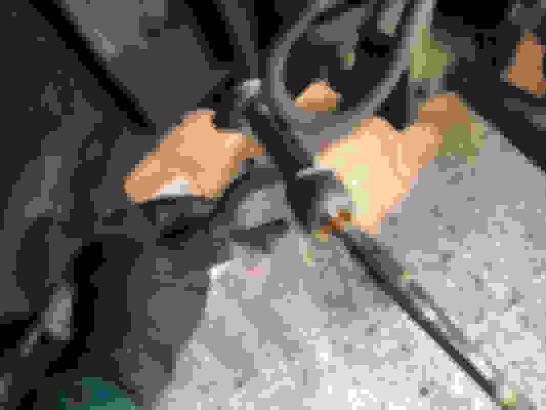
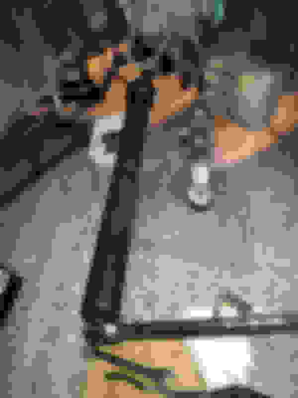
So, I used some heavy bolts, nut, washers, and click style bar clamp to generate massive torque despite limited space. Here is my arrangement for breaking the jam nut free. For breaking the outer tie rod free, the greater span distance required two bolts, one in each wrench end. With bolt ends pointed at each other, I could put clamp on the bolts and click away until the rust gave way.
Yes, this qualifies as rust in the threads. You can also count turns as you remove the outer tie rod, but I already marked the jam nut position earlier.
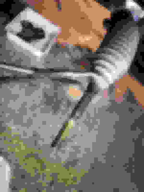
Speaking of which, the jam nut needs to come off so I can remove the tie rod boot.
Outer boot clip comes off with just a squeeze like a hose clamp.
Jam nut is in the way and blocked by rust on threads. Steel brushed the rusty thread and PB blaster allowed the nut to unthread completely.
Inner boot clamp is a bit harder to remove. If you squeeze just the right bits, it does pop open. I managed that just once. The other I simply cut off.
Removing boot from tie rods can be tough because smaller end has to ride past a groove in the tie rod. A hose plier convinces the boot to come off.
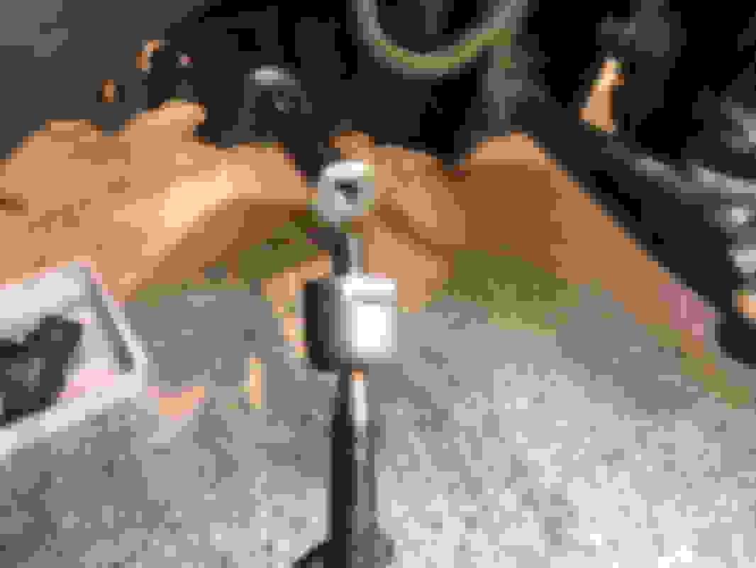
An inner tie rod tool is much easier to break inner tie rod free than trying to use a conventional wrench with limited space under car. I tried and could not budge it with a normal wrench under the car.
An inner tie rod tool will also be handy to get correct torque when installing the new inner tie rod. Get one.
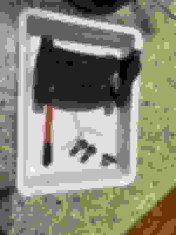
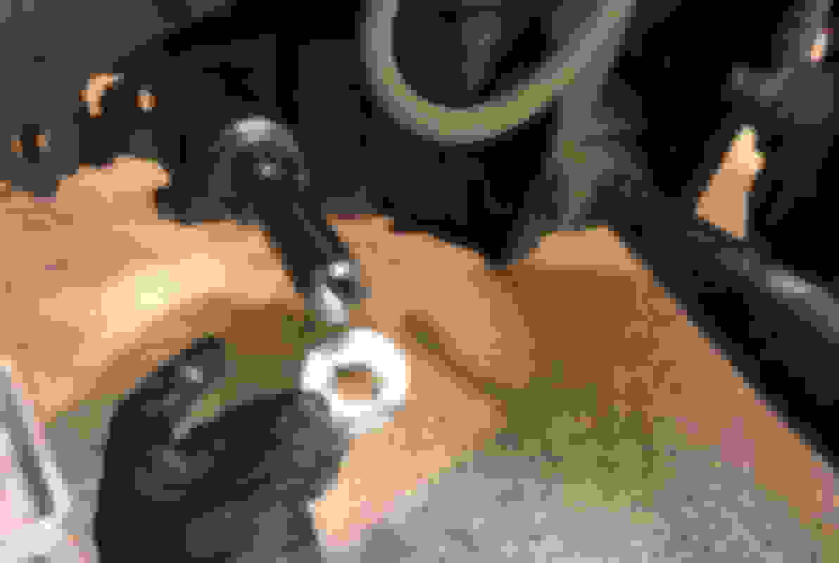
Peen claw washer back so it no longer prevents inner tie rod rotation. One can flatten and re-use the claw washer, but I obtained new ones rather than trusting re-bent metal.
Place correct size tool adapter onto flats of inner tie rod.
Attach inner tie rod tool and a breaker bar easily frees inner tie rod from steering rack. BTW, now is a perfect time to inspect your steering rack. There should be minimal to no hydraulic fluid coming out from your steering rack. If you detect a leak, you may need a new steering rack soon.
Tie rod is free
You can remove the old claw washer to reform it, but in retrospect, it might be a good reminder to INSTALL a claw washer later!
Last edited by Seattle SCone; 11-19-20 at 05:35 AM.
Tons more to post, but is going to take a while. Some of the picts were taken out of this sequence because I forgot to get some picts along way and had to go back to get good illustrations of the components. For instance you'll notice the knuckle and lower caster arm sometimes disappear/reappear in the photos for the tie rod ends.
Last edited by Seattle SCone; 11-19-20 at 05:39 AM.
We have previously loosened the two bolts holding ball joint to steering knuckle. Double check that those are indeed easy to turn. If not loosen to where they free turn, but do not fully remove.
The ABS sensor should also already be detached from the knuckle/hub.
Direct attention to the upper control arm and its connection to the top of knuckle. Remove cotter pin from UCA castle nut.
Remove 17 mm castle nut (64 ft lbs) from UCA stud.
Pitman ball joint separator pops knuckle free from UCA ball joint.
Careful! Top of knuckle will tilt forward when the ball joint pops free. This is one reason not to completely remove those two bolts attaching knuckle to lower ball joint.
Fully remove the two 17 mm (83 ft lb) bolts from below the lower ball joint to completely free knuckle hub assembly.
Lower ball joint is fully visible now that knuckle hub assembly has been removed. The lower ball joint is held in place only by the previously loosened (83 ft lb) 19 mm nut
Use a larger Pitman ball joint puller to separate ball joint. BTW the ball joint separator set I used is this one...
 11-19-20, 12:06 AM